Week 9 - Project 1 - Door Trim Lower with Engineering Features
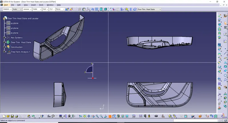
DOOR TRIM LOWER HEAT STAKE AND LOCATORS
Aim: To Create the Door trim lower component through the given Class-A surface.
Objectives:
• Creation of Tooling axis with appropriate draft angle.
• Creation of other surfaces (eg, B and C surfaces) for creating a solid component. • Perform Draft analysis on Class A surface and Solid model hence created.
Tooling Axis creation:
It is defined as the direction in which the mould/core and cavity open. Selection of the direction of the tooling axis depends on the ease at which components can be easily ejected.
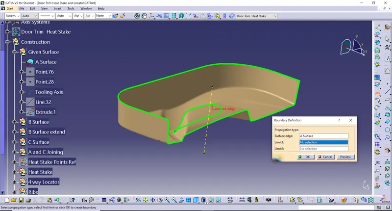
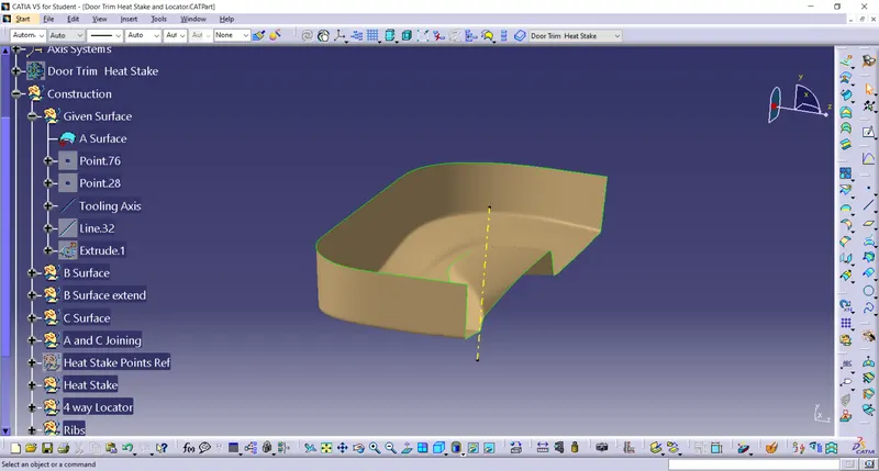
By analysing the component the most easily ejectable direction is somewhere close to the Z direction,(might be inclined to it) so we have made a sketch on the YZ plane of Axis System) to create a bisecting line considering the 2 faces which might be difficult to be tooled.
Draft Analysis
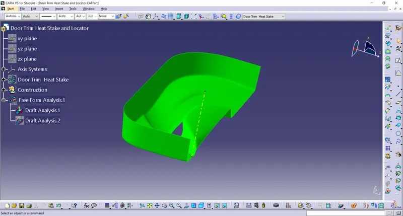
The draft analysis technique is used to analyze whether our part model created in CAD is manufacturable based on the draft condition applied. Here the part should get easily removed from the panel dies (in case of Sheet metal part) or Mold (in case of plastic).
No parts can be ejected from the tool if it is having a straight 90-degree profile from its base surface. A small draft angle is provided to each and every area of the component in order to get easy removal of the component from the tool.
Here we are providing a direction in which components should eject in order to get easy removal of components from the tool. In other words, it also lets us know whether the model is having a draft angle and how much is the draft angle from the tool direction.
CLASS B SURFACE:
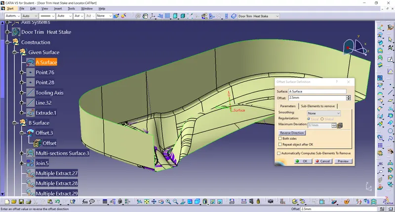
To create the class B surface, I considered the entire surface has 3 parts 'Upper, Walls, and Base surface'. If we directly offset the class A surface, fillets may lead to cause an error, to avoid the errors we need to extract the surfaces and untrim the extracted surfaces and extrapolate those untrimmed surfaces with point continuity. Now trim those extrapolated surfaces to the required shape. And finally, fillets were given to the final trim.
Given Thickness Value 2.5mm Offset each Following Components
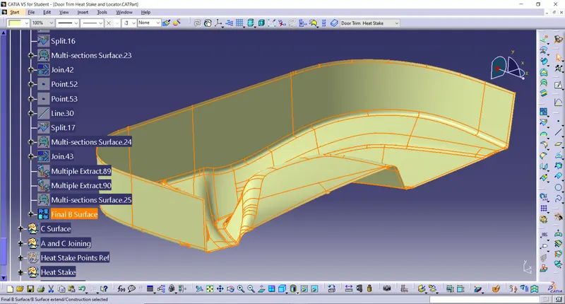
Wheather we checked Once Created B Surface without any Patch or Gap in between them.
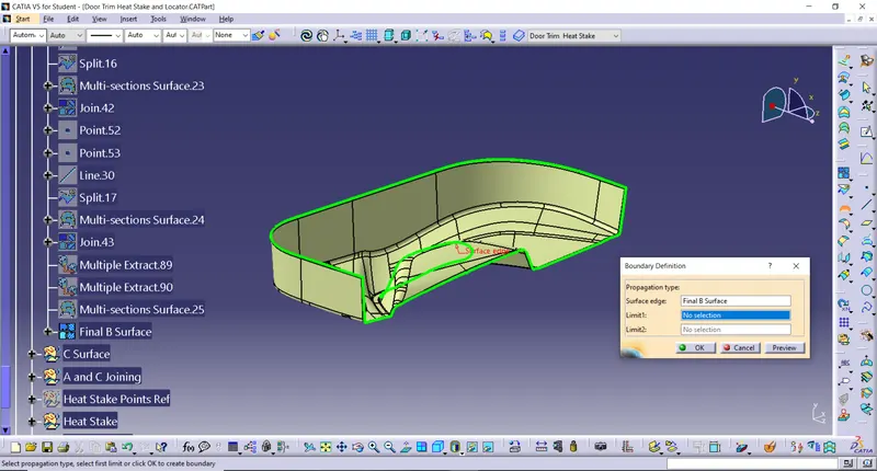
Class C Surface:
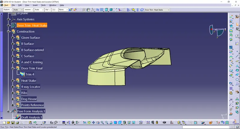
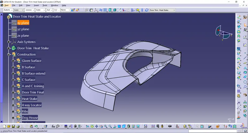
It is the combination of Class A, Class B and Class C surfaces. To create a class C surface, I used the sweep command by considering the outer boundary of the class A surface. In the sweep command, go to the 'line' command in the 'profile' block and the subtype is 'with draft direction'. Now select the outer boundary and tooling axis, give 3 deg in the angle (the draft angle for a plastic component is 0.5 to 3 deg) and select the direction to sweep, in this condition the class B surface is under the class A surface so select the inside down arrow to sweep. The same procedure is repeated for the two circles on the class A surface. Now I joined all the sweeped surfaces by using the 'join' command and then I trimmed the Class A, Class B and Class C surfaces to make a closed surface, to make a Solid body.
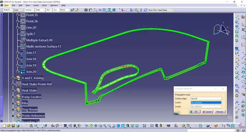
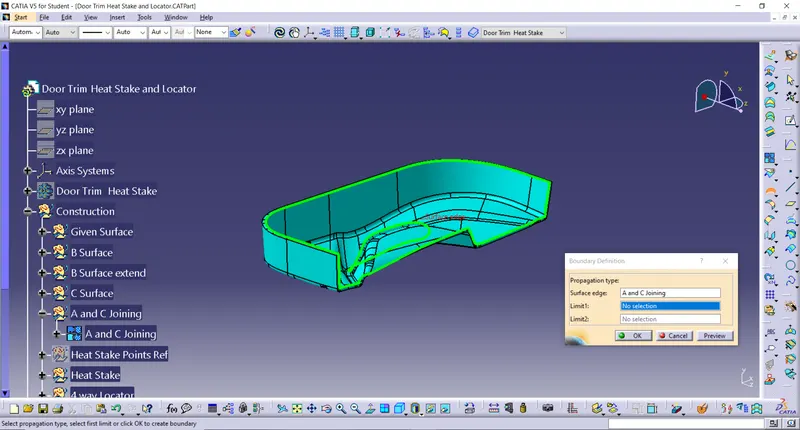
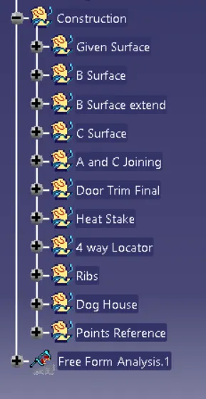
Joining A and C Surface
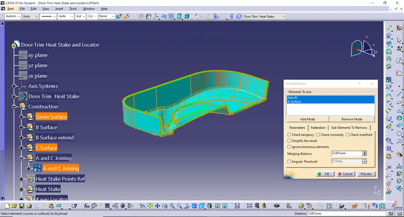
CREATING THE RIB
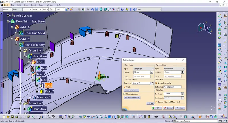
Ribs are thin wall protrusions that extend perpendicularly from a wall or plane. They are usually found in clusters offering support to a plane that would have otherwise been too thick, but can also be stand-alone support for a single wall. They are commonly used to provide additional support and strength to a part. Thickness and location are essential to rib design.
First, the base surface where the rib has to be created is extracted using the Extract command.
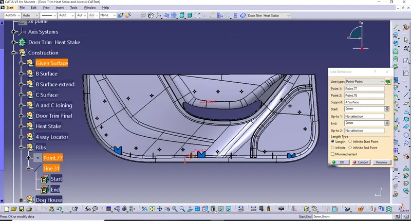
The draft is applied to the sides of the ribs. As per the design rule, the ideal draft angle is 0.5 deg
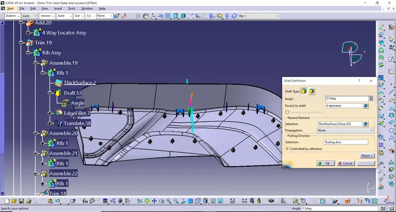
Then fillet is applied to the faces of the rib. As per the design rule, the fillet can be 0.25 mm.
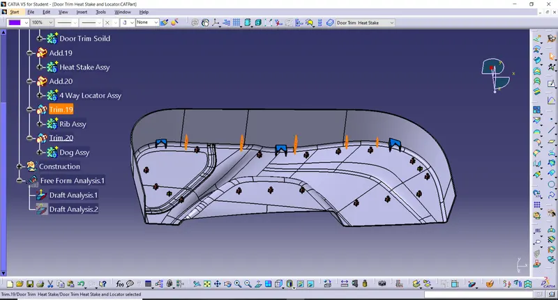
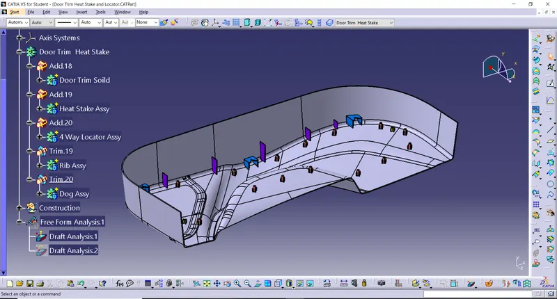
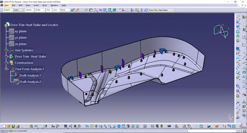
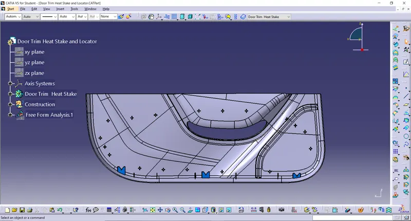
The locators restrict all the other degrees of freedom except the translation along the direction of tooling axis Le along y-axis. For restricting that degree of freedom we will be using the heat stakes.
In heat staking, we use local heating and cooling to raise the temperature of plastic components and allow plastic reforming to be carried out.
4 Way Locator
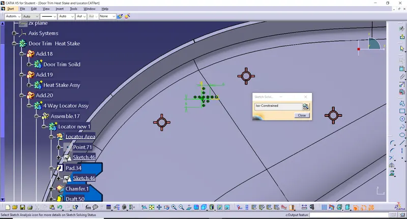
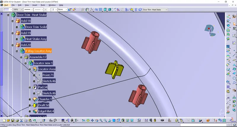
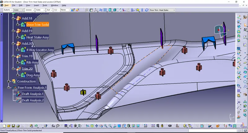
These heat stakes will enter the mating component and using a heat staking machine these heat stakes are melted and cooled. When cooled this will get hardened and the two components will stick together. Thus all degrees of freedom are arrested
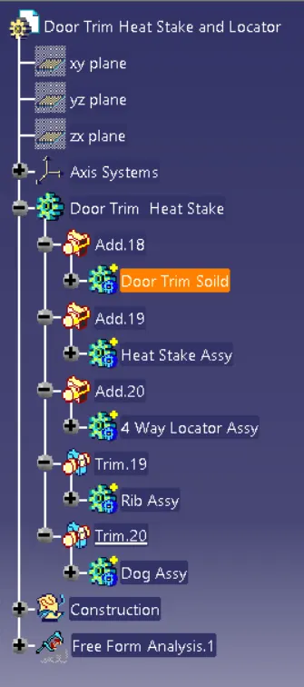
Then, the ribs are created by following the rib design rules.
CREATING THE DOGHOUSE
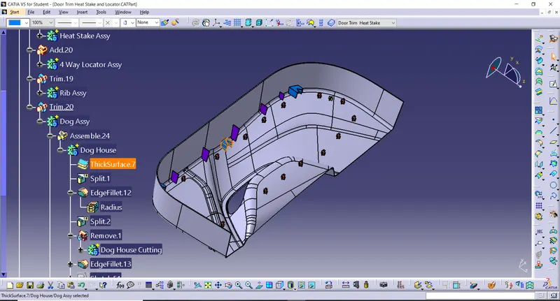
The dog house is an engineering feature used in the plastic trim design. Dog houses are used as a supporting feature. Sometimes other engineering features like snaps; locators, etc. are mounded on them to increase their strength.
The doghouse is created by following the design rules.
The nominal wall thickness guide range is from 0.75 mm to 3 mm for reinforced materials and 0.5 mm to 5 mm for unreinforced materials.
Related Courses
WALL THICKNESS (W) = 0.70 (NOMINAL THICKNESS OF PLASTIC MATERIAL)
This process is usually done by Thicken surface command.
Conclusion
Here, Sucessfully to create the Door Trim Lower Plastic component through the above-given Class-A surface, by giving the 'Tooling axis' and 'Draft analysis' to the Door Trim Lower Heat Stakes and Locators.