Photo Realistic Rendering
Design, Assembly and Rendering of American Chopper Bike
Objective:
To Create a Design, Assembly and Rendering of the American Chopper by Using Soildworks And Soildworks Visualize
Introduction:
Introduce the American Chopper Motor Vehicle i designed by using Soildworks. This is Totally different Perpestive make this chopper for me, Because Its tyoically Self Learning Experience i got while i am sketching the Chopper. This type Chopper Using at 1950's.
Design Methodology
Design are Parts
Assembly are Parts
Rendering
Design are Parts
- Transmission Belt
- Kick Stand
- Pedal
- Chain
- Rear Fender
- Front Fender
- Oil Tank
- Rear Wheel
- Front Wheel
- Chassis
- Front Fork
- Engine
- Gas Tank
Transmission Belt
- Required Dimension As we sketched to using Sketching tools and Tangent relation Between Every arc of the Drag.
- Using Feature tool bar extrude required Dimensions and fillet the standard size of 3mm.
Sketch Tool
- Line
- Arc ( Three Point Arc)
- Fillet
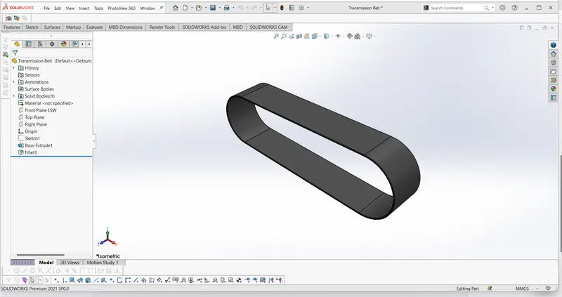
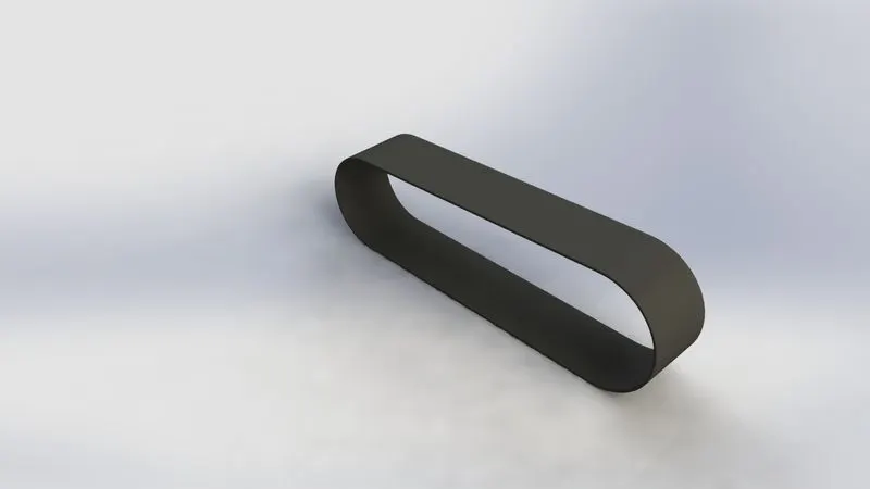
Design of Transmission Belt Photo Realistic Rendering of Transmission Belt
Function
Transmitts the Power Engine to Gear Box Using of Transmission Belt.
Kick Stand
- Required Dimension As we sketched to using Sketching tools and Tangent relation Between Every arc of the Drag.
- Using Feature tool bar extrude required Dimensions and fillet the standard size of 3mm.
- Adding a Dome Feature and Split the As need to cut a part.
- To create Reference Plane of the different view to sketch.
Sketch Tool
- Line
- Arc ( Three Point Arc)
- Circle
- Offset
- Spline
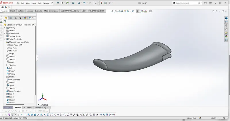
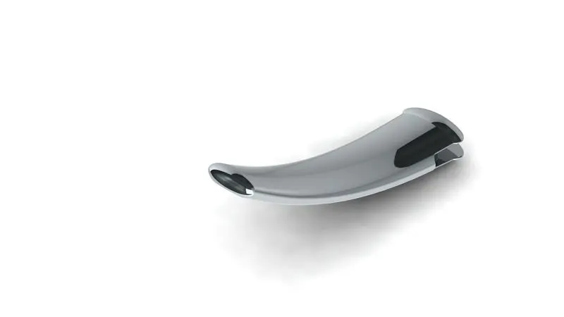
Design of Kick Stand Photo Realistic Rendering of Kick Stand
Function:
Although the primary use for a bicycle stand is for parking, it is useful at times to use it for adjustments.
Front Fender
- Required Dimension As we sketched to using Sketching tools and Tangent relation Between Every arc of the Drag.
- Using Feature Tool bar Extrude the cut required dimesion not an sharp curves.
Sketch Tool
- Line
- Arc ( Three Point Arc)
- Circle
- Offset
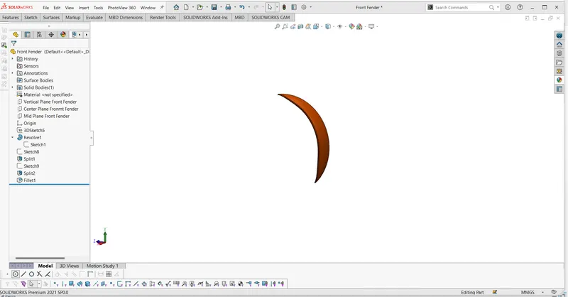
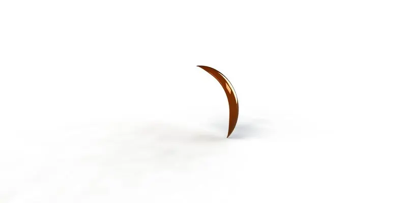
Design of Front Fender Photo Realistic Rendering of Front Fender
Function:
Its primary purpose is to prevent sand, mud, rocks, liquids, and other road spray from being thrown into the air by the rotating tire.
Rear Fender
- Required Dimension As we sketched to using Sketching tools and Tangent relation Between Every arc of the Drag.
- Using Feature Tool bar Extrude the cut required dimesion not an sharp curves.
Sketch Tool
- Line
- Arc ( Three Point Arc)
- Circle
- Offset
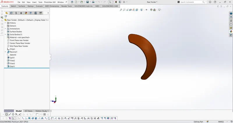

Design of Rear Fender Photo Realistic Rendering of Rear Fender
Function
Its primary purpose is to prevent sand, mud, rocks, liquids, and other road spray from being thrown into the air by the rotating tire.
Chain
- Required Dimension As we sketched to using Sketching tools and Tangent relation Between Every arc of the Drag.
- Using Feature tool bar extrude required Dimensions and fillet the standard size of 3mm.
- Adding a Dome Feature and Split the As need to cut a part.
- To create Reference Plane of the different view to sketch.
- To Understand the Circular Pattern.
- To create a Plates and Pins for the Chain.
Sketch Tool
- Line
- Arc ( Three Point Arc)
- Circle
- Offset
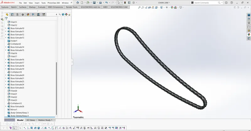
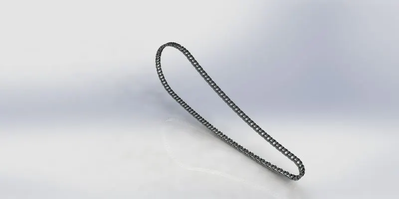
Design of Chain Photo Realistic Rendering of Chain
Function:
Its Transfer Power from the Engine(Gear Box) to Wheel with help of Sprackets.
Oil Tank
- Required Dimension As we sketched to using Sketching tools and Tangent relation Between Every arc of the Drag.
- Using Feature Tool bar Extrude the cut required dimesion not an sharp curves.
Sketch Tool
- Line
- Arc ( Three Point Arc)
- Circle
- Offset
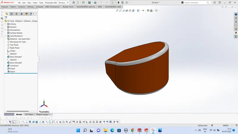
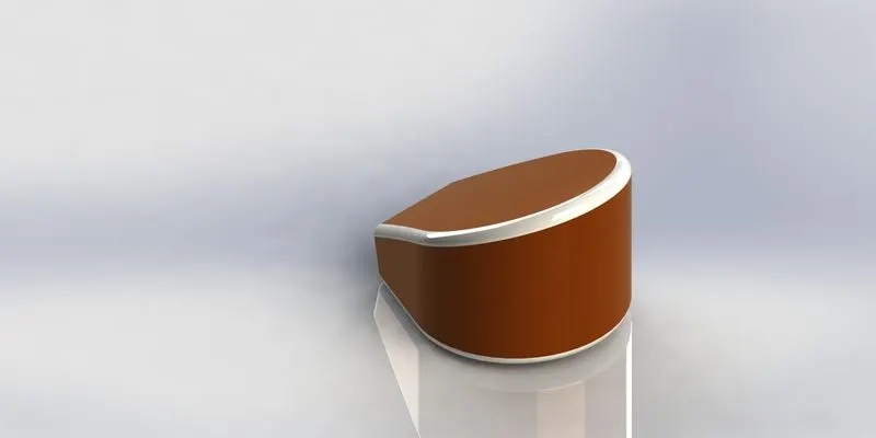
Design of Oil Tank Photo Realistic Rendering of Chain
Function:
Oil tanks store fuel oil for heating systems on commercial and residential properties
Pedal
- Required Dimension As we sketched to using Sketching tools and Tangent relation Between Every arc of the Drag.
- Using Feature Tool bar Extrude the cut required dimesion not an sharp curves.
Sketch Tool
- Line
- Arc
- Circle
- Offset
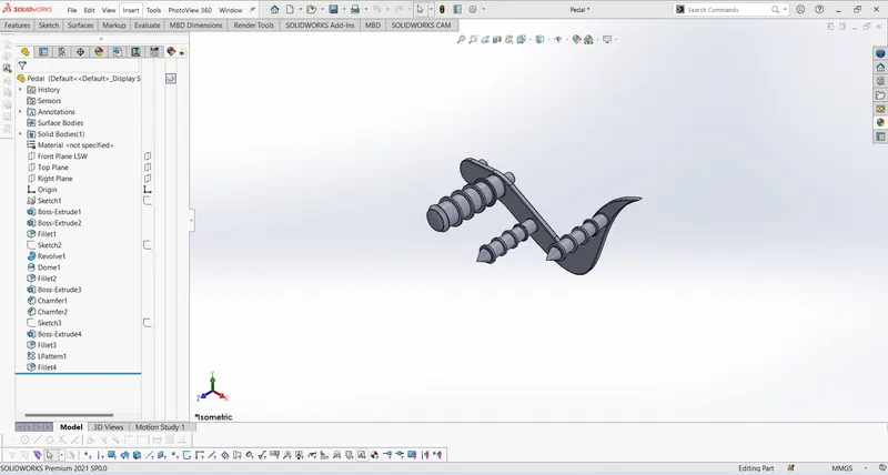
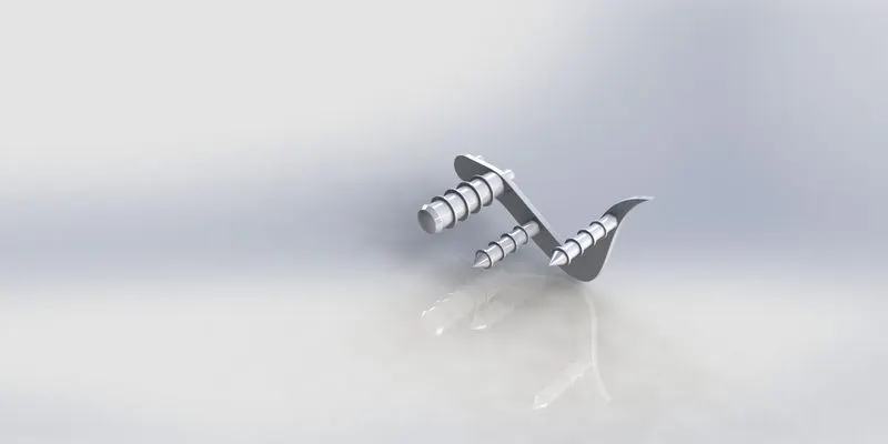
Design of Pedal Photo Realistic Rendering of Pedal
Function:
- Required Dimension As we sketched to using Sketching tools and Tangent relation Between Every arc of the Drag.
- Using Feature Tool bar Extrude the cut required dimesion not an sharp curves.
- Using Standard Diameter of the Tire 22inch
Sketch Tool
- Line
- Arc
- Circle
- Offset
- Convert entities
Parts Contained Of Front Wheel
- Rim
- Disc (Rotor)
- Brake Caliper
- Tire
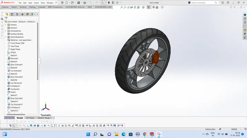
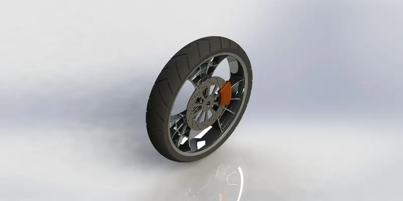
Design of Front Wheel Photo Realistic Rendering of Front Wheel
Rear Wheel:
- Required Dimension As we sketched to using Sketching tools and Tangent relation Between Every arc of the Drag.
- Using Feature Tool bar Extrude the cut required dimesion not an sharp curves.
- Using Standard Diameter of the Tire 22inch
Sketch Tool
- Line
- Arc
- Circle
- Offset
- Convert entities
Parts Contained Of Rear Wheel
- Rim
- Disc (Rotor)
- Brake Caliper
- Tire
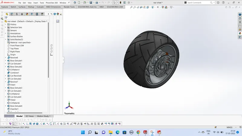
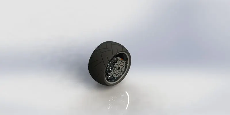
Design of Rear Wheel Photo Realistic Rendering of Rear Wheel
Function:
Rear-wheel drive. Rear-wheel drive (RWD) is a form of engine and transmission layout used in motor vehicles, where the engine drives the rear wheels.
Front Fork
Sketch Tool
- Line
- Arc
- Circle
- Offset
- Convert entities
- Projection Curve
- Spline
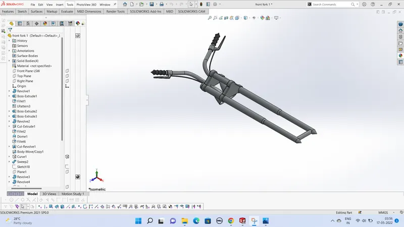
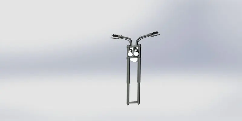
Design of Front Fork Photo Realistic Rendering of Front Fork
Function:
Bicycle PH Type Front Forks are the part of a bicycle which hold the front wheel. They typically consist of two blades which are joined at the top by ... More Backed by a team of diligent professionals and technocrats, we are engaged in offering our clients the best in line Front Fork.
Chassis
- Required Dimension As we sketched to using Sketching tools and Tangent relation Between Every arc of the Drag.
- Using Feature tool bar extrude required Dimensions and fillet the standard size of 3mm.
- Adding a Dome Feature and Split the As need to cut a part.
- To create Reference Plane of the different view to sketch.
- To Understand the Circular Pattern.
- Main part role here played photo blue Print of chopper
Sketch Tool
- Line
- Arc
- Circle
- Offset
- Convert entities
- Projection Curve
- Spline
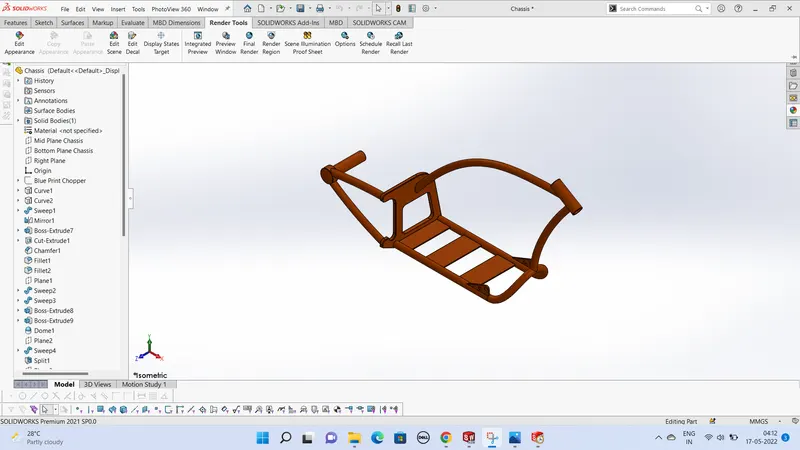
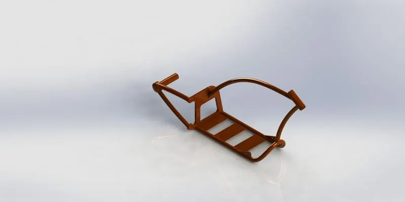
Design of Chassis Photo Realistic Rendering of Chassis
Function:
The primary function of the motorcycle frame (also known as Motorcycle Chassis) is to hold the different parts together in one rigid structure and prevent it from falling apart. In other words, a motorcycle frame is its core structure or skeleton made to support the suspension, seats, handlebars, fuel tank, and engine.
Engine
- Required Dimension As we sketched to using Sketching tools and Tangent relation Between Every arc of the Drag.
- Using Feature tool bar extrude required Dimensions and fillet the standard size of 3mm.
- Adding a Dome Feature and Split the As need to cut a part.
- To create Reference Plane of the different view to sketch.
- To Understand the Circular Pattern.
- Main part role here played photo blue Print of chopper
- Linear Pattern and Sweep using for that make of engine.
Sketch Tool
- Line
- Arc
- Circle
- Offset
- Convert entities
- Projection Curve
- Spline
- Fillet
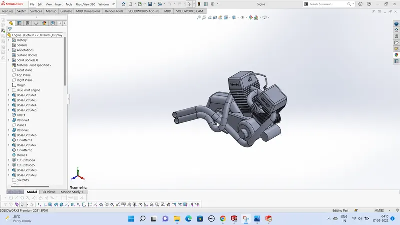
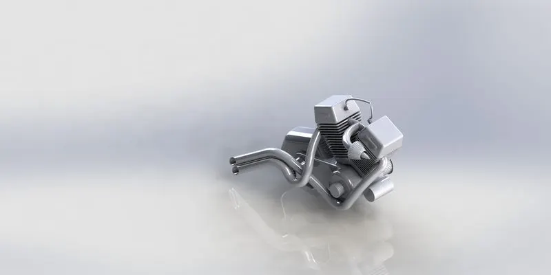
Design of Engine Photo Realistic Rendering of Engine
Function:
Its a heart of the motor cycle,The engine is the vehicle’s main source of power. The engine uses fuel and burns it to produce mechanical power. Chemical Energy converted into Mechanical Energy
Gas Tank
- Required Dimension As we sketched to using Sketching tools and Tangent relation Between Every arc of the Drag.
- Using Feature tool bar extrude required Dimensions and fillet the standard size of 3mm.
- Adding a Dome Feature and Split the As need to cut a part.
- To create Reference Plane of the different view to sketch.
- To Understand the Circular Pattern.
- Main part role here played photo blue Print of chopper.
- In this Drawing fully utilise by Surface Modeling.
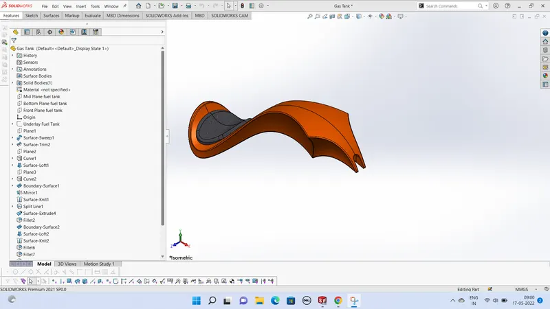
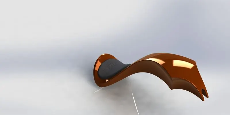
Design of Gas Tank Photo Realistic Rendering of Gas Tank
Function:
A fuel tank (also called a petrol tank or gas tank) is a safe container for flammable fluids. Though any storage tank for fuel may be so called, the term is typically applied to part of an engine system in which the fuel is stored and propelled (fuel pump) or released (pressurized gas) into an engine.
Explanation of Tools
Line:
A row of closely spaced dots will look like a continuous line
Circle:
A round plane figure whose boundary (the circumference) consists of points equidistant from a fixed point (the centre)
Offset:
Counteract (something) by having an equal and opposite force or effect
Arc:
A part of a curve, especially a part of the circumference of a circle.
Convert Entities:
Basically used to make a replica of sketch entity or its dimensions in the same plane or another co-ordinate.
Fillet:
The Sketch Fillet tool trims away the corner at the intersection of two sketch entities to create a tangent arc.
Loft:
The loft feature creates a shape by combining many profiles and guiding curves.
Extrude:
Create a New Part. Select the desired plane, click on the Top plane and select sketch Make a rectangle with the origin of the sketch as the origin of the rectangle.
Center Point Arc:
Centerpoint arc is a curve or part of circle which is drawn by fixing the center point, start and end point of the arc.
Sweep:
Consider a paperclip, the body can be created using an extrude then filleting the edges to achieve a circular profile.
Revolve:
The sketch for a solid revolved feature can contain multiple intersecting profiles. With the Selected Contours pointer (available when you click Selected Contours in the PropertyManager), you can select one or more intersecting or non-intersecting sketches to create the revolve.
Mates:
The most common mates in SolidWorks assemblies are coincident and concentric due to how often things are made to be flush or aligned with one another.
Assembly Of Chopper
- All parts of chopper be ready for that final assembly.
- Open the Assembly in solidworks now ready mates the parts as required standard plane option.
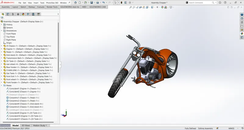
Assembly of American Chopper
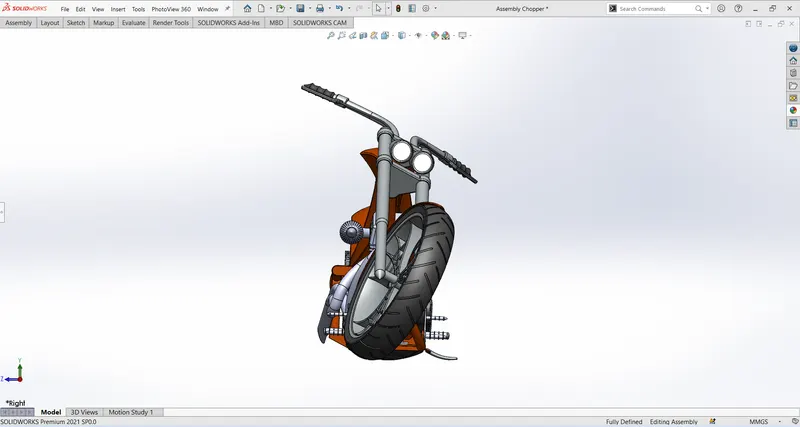
Front View of Chopper
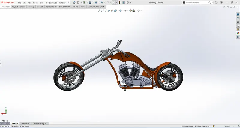
Side View of Chopper
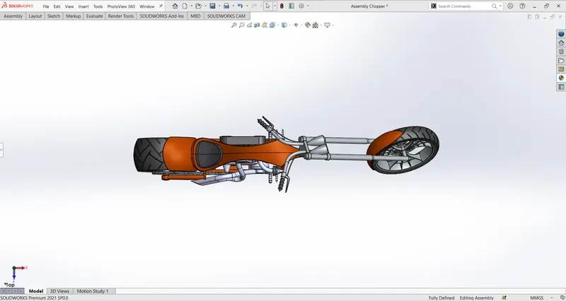
Top View of Chopper
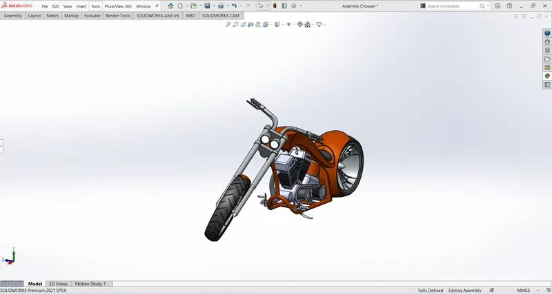
Isometric View of Chopper
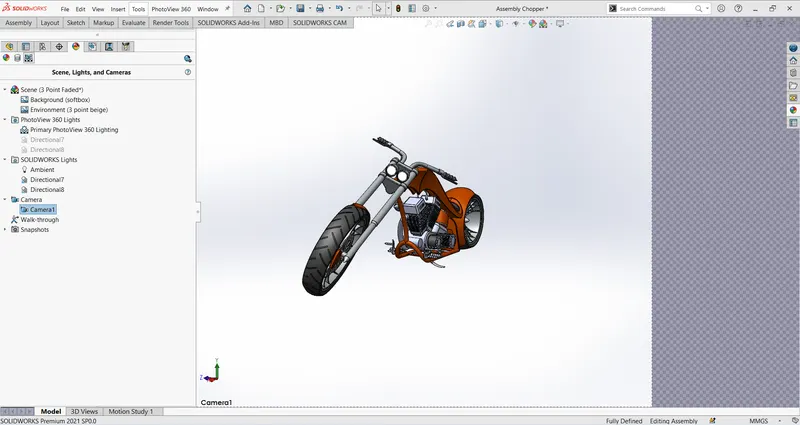
Camera Setup View of Chopper
Rendering of Chopper
- Rendering nothing but its makeup the external perpestive of view.
- Graphical Design , decals,Editing Scene and as well lighting effects. Max. of that Realistic view.
Decals used in Parts
- Gas Tank
- Oil Tank
- Rear Render
Gas Tank
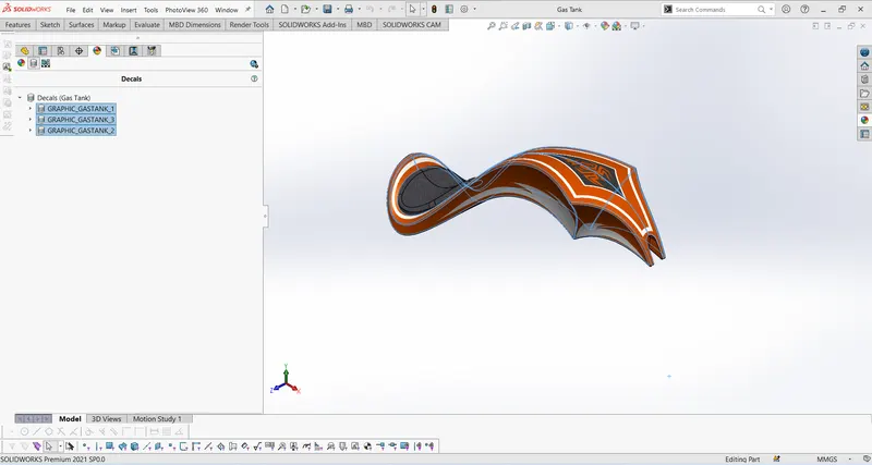
Decals using in Gas Tank
Oil Tank
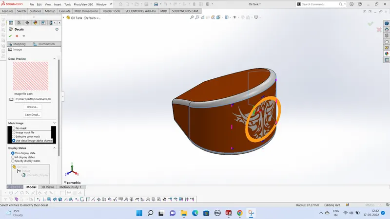
Decals using in Oil Tank
Rear Fender
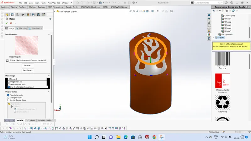
Decals using in Rear Fender
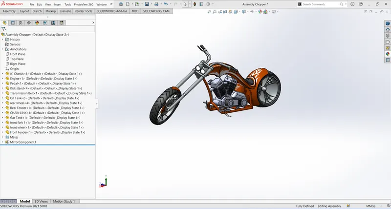
Assembly of applied decals images at Chopper
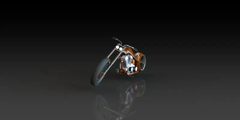
Photo Realistic Front View American Chopper
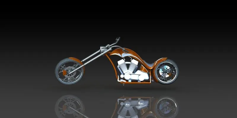
Photo Realistic Camera Setup View American Chopper
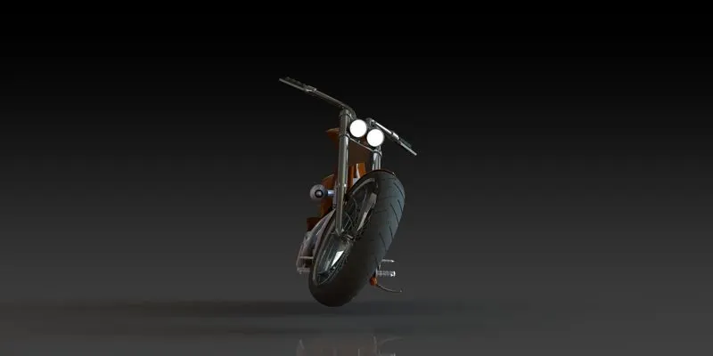
Photo Realistic Front View American Chopper
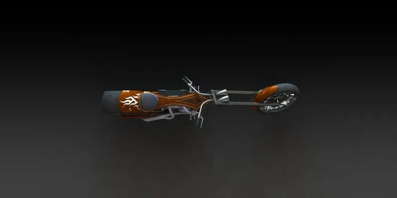
Photo Realistic Top View American Chopper
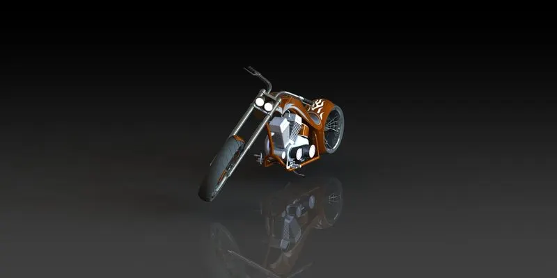
Photo Realistic Isometric View American Chopper
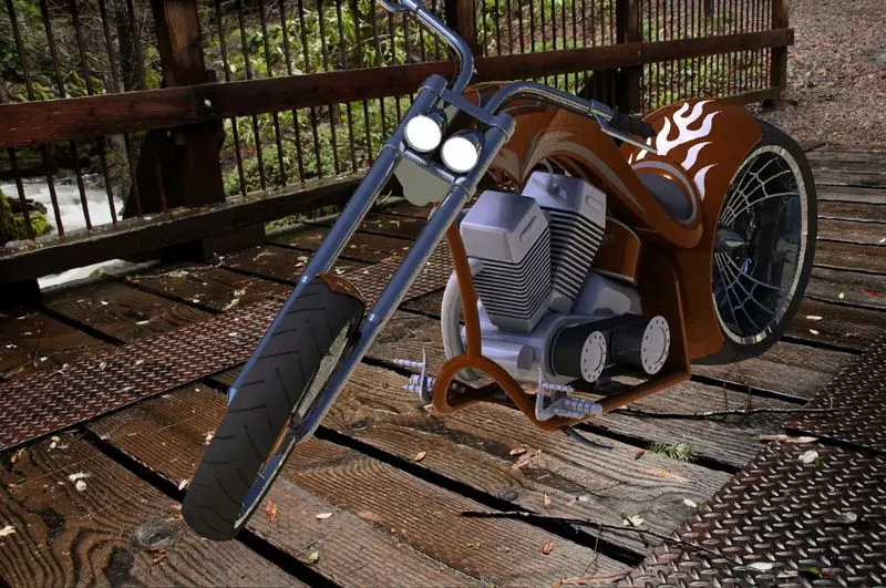
Photo Realistic Parking View American Chopper
Visualize Solidworks
- SOLIDWORKS Visualize (formerly known as Bunkspeed) provides a suite of standalone software tools that combine industry-leading rendering capabilities with visual design-oriented features and workflows, allowing easy and fast creation of visual content that communicates a design’s vision, passion, and emotion.
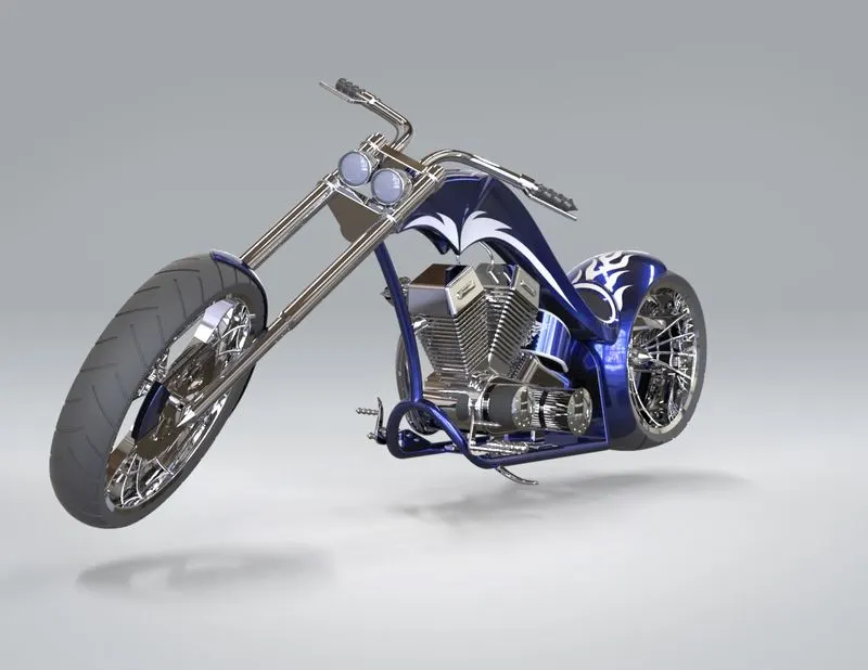
Modified Color of American Chopper Metallic Blue
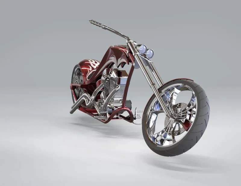
Modified Color of American Chopper Metallic Red
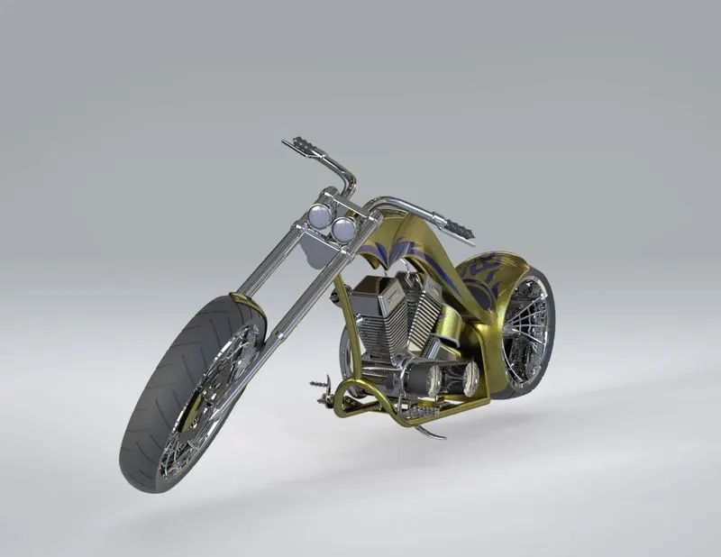
Modified Color of American Chopper Metallic Yellow
Conclusion:
Design, Assembly and Rendering the American Chopper using of Soildworks and Soildworks Visualize sucessfully done my project.