Week 9 - Project 1 - Door Trim Lower with Engineering Features
Door Applique:
Aim: Create the Door applique Plastic Component from the given Class A Surface. To begin with, the tooling axis for the given Class A surface should be created meeting the requirements of the draft angle and at the end perform the Draft analysis on the model. Design of Heatstakes and Locator as per the designing consideration anf finally perform draft analysis.
Class A Surface: Class A surface is the asthethic surface that is created through scaning of clay model. This Class A surface is a input CAD model for the part design.
Class B Surface: Class B surface is created in a certain distance according to the thicknesss of the part. Class B surface contains all the engineering components.
Class C Surface: Class C surface joins the Class A & B surfaces.
In this model we have focused on the following things:
- Tooling Axis
- Draft analysis
- Class B surface
- Class C surface
- Making a solid model from the surface
- Creating Heatstakes and Locator
Class A Surface
- The 3D CAD part file of the Class A surface is given. Next step is to check the continuity of the Class A surface. This is to ensure there is no gap between the surface. If any found we must resolve that first.
- Analyse the Class A surface through visual inspection
- To make sure there is no gap in between the Class A surface, we can also check with the help of Join or boiundary command.
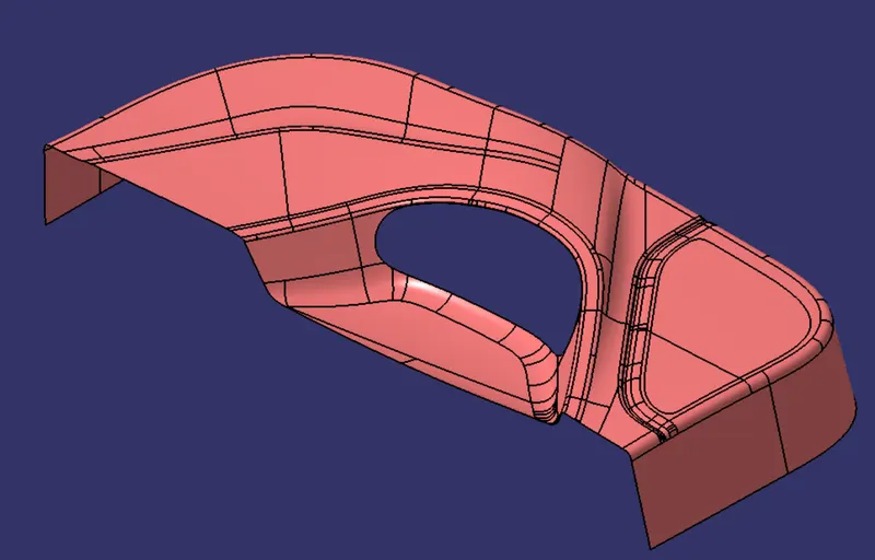
Figure: Class A surface
Tooling Axis:
- Tooling axis represents the opening and the closing of the mold core and the cavity during the manufacturing of the components. A plastic product designer should consider the best tooling direction to cutdown the cost of the component very less.
- Firstly, Check the best tooling direction for the given surface.
- We can find out the best tooling direction by cross checking all the three axes.
- Here we can find out that the best tooling direction for the class-A surface is along Y-axis direction.
- Next, extract a surface from the Class A surface and create a midpoint on that surface.
- Then from the created midpoint create a line along the Y-axis direction. Thus this created line is "Tooling Axis".
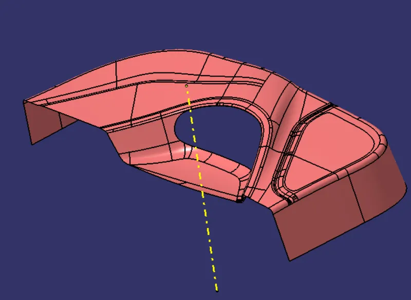
Figure: Tooling Axis on Class A Surface
Draft Analysis
- The Draft Analysis is a command enables you to detect if the part you drafted will be easily removed. This type of analysis is performed based on colour ranges identifying zones on the analysed element where the deviation from the draft direction at any point, corresponds to specified values.
- Draft analysis is done after determining the tooling axis, draft analysis is used to check whether the minimum draft is maintained or not.
- Change the view mode of the component to be in customized parameter mode and then select the shading mode as materials.
- Then Using the "Draft analysis" command, click on the compass to define the current drafting direction and lock the compass on the tooling axis and perform the draft analysis by clicking on the Class A surface.
- Click on the analyses under the running point to check the draft analysis on the individual faces. It shows how much draft on specific points when we move the cursor point.
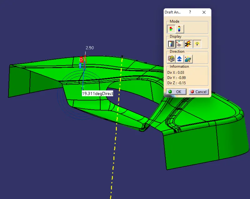
Figure: Draft Analysis on Class A surface
Class B Surface:
- Offset the given class A surface to 2.5mm inwards direction
- From the offset of Class A surface, the new Class B surface formed has few patches as shown in figure.
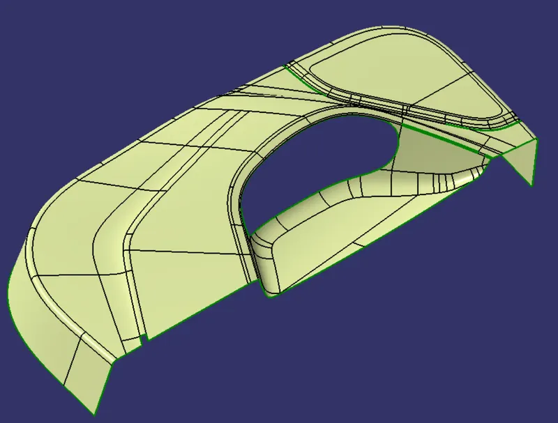
Figure: Class B Surface with patches
- Rework on the patches and discontinuity of the offset surfaces using the features like extract, multi-extract, sweep, multi-section surfaces, extrapolate.
- To ensure the continuity of the Class-B surfaces check the boundary command to find out the boundary.Hence class-B surface creation is done.
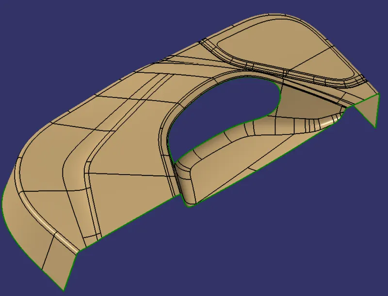
Figure: Class B surface

Figure: Class B surface Boundary
Class C Surface
- Class C surface joins the Class A surface and Class B surface.
- Since it is a complex Class A surface, we perform Sweep operation of 90 degrees with reference to the surface option by creating the outer and inner boundary.
- Finally, we join the Class A and Class C surfaces
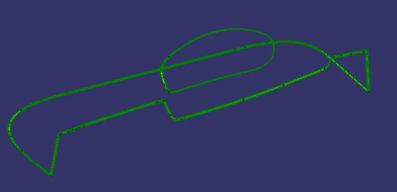
Figure: Class C Surface
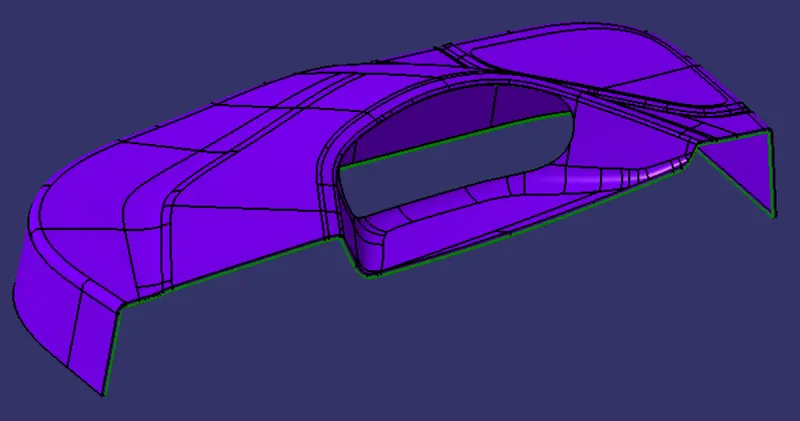
Figure: Class A+C Surface
Final Closed Surface
- Next step is to join the Class A+C surface with the Class B surface to get the final closed surface
- Some error may arise while applying the trim operation as some surfaces may not intersect each other properly.
- We extrapolate those surfaces and apply the trim operation to finally get the closed surface.
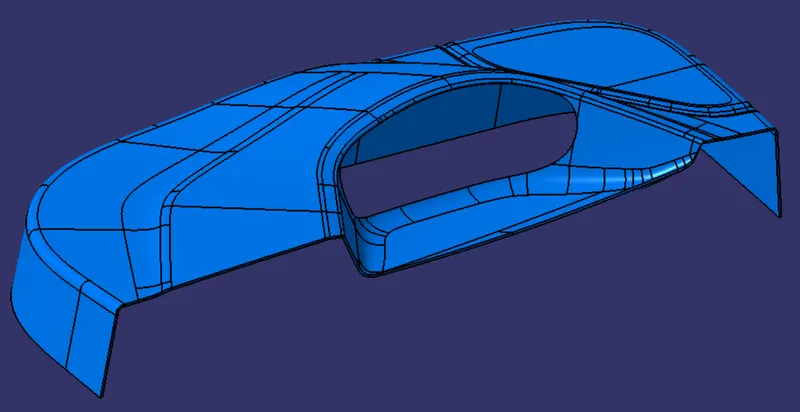
Figure: Final Closed Surface
- Switch to the " Part Workbench" , then apply the Closed surface command on the Final Closed surface.
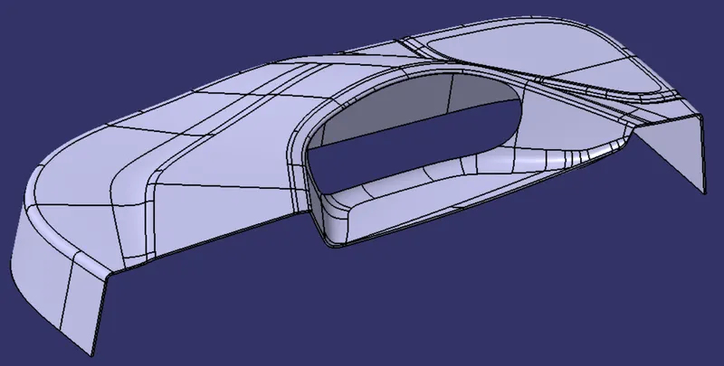
Figure: Final Closed Surface in Part Body
Draft Analysis on Final Closed Surface
- Change the view mode of the component to be in customized parameter mode and then select the shading mode as materials.
- Using the "Draft analysis" command, click on the compass to define the current drafting direction and lock the compass on the tooling axis and perform the draft analysis by clicking on the Closed body.
- Click on the analyses under the running point to check the draft analysis on the individual faces. It shows how much draft on specific points when we move the cursor point.
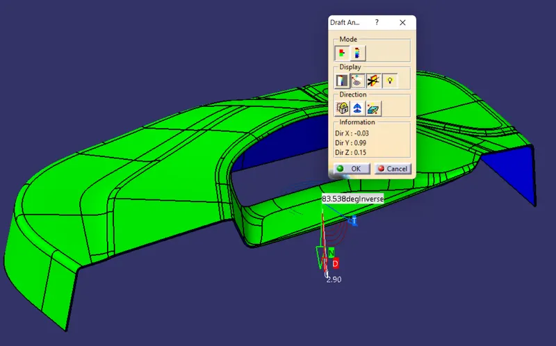
Figure: Draft Analysis on Final Closed Partbody
Heat Stakes & Locator:
- Locator are designed as per the design consideration
- Firstly, the sketch of the locator is created as shown in figure
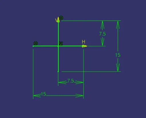
Figure: Sketch of Locator
- Next, the sketch is thick padded along the tooling axis direction
- Next, a draft od 0.5 deg on all the required faces of the locator in tooling axis direction.
- Further a chamfer of 3mm length and 45 deg angle is provided and edge fillet of 0.3mm is applied on it
- Using Trim boolean command, the Locator part body is added to the Door applique part body.
- Another Locator partbody is added on the Door applique using the translation command on the new locator partbody.
HeatStakes :
- Heatstakes are designed as per the design rules
- The sketch of the Heatstake is created as show in figure
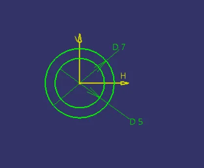
Figure: Sketch of Heatstake
- Next, the sketch is Padded in the direction of the tooling direction and draft of 0.5 deg is applied on it along the tooling axis direction.
- Next, edge fillet of 0.25mm is applied on it.
- Further, supportive ribs are added on the heatstakes
- Using the boolean operation, heatstake partbody is added on the Door applique partbody and the other body are translated and added further using boolean command.
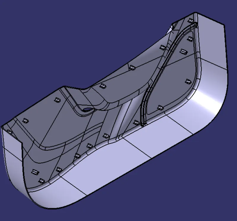
Figure: Isometric View
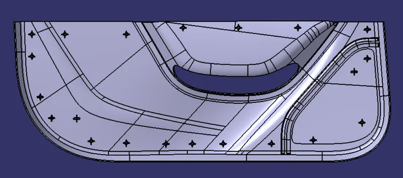
Figure: Side View
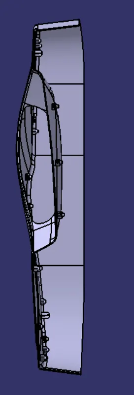
Figure: Top View
Draft Analysis:
- Finally, draft anaysis is performed on the complete Door applique
- Change the view mode of the component to be in customized parameter mode and then select the shading mode as materials.
- Using the "Draft analysis" command, click on the compass to define the current drafting direction and lock the compass on the tooling axis and perform the draft analysis by clicking on the Final Closed body.
- Click on the analyses under the running point to check the draft analysis on the individual faces. It shows how much draft on specific points when we move the cursor point.
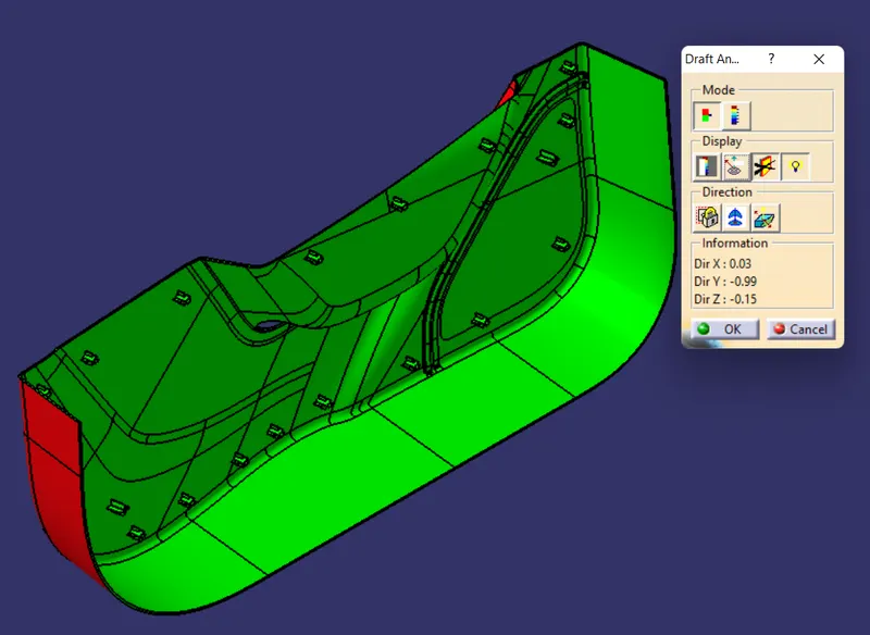
Figure: Isometric View of draft analysis on the Final closed body
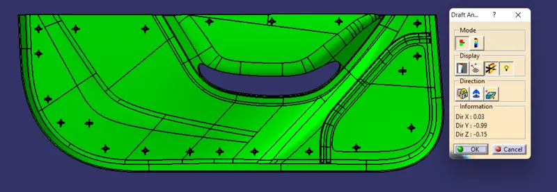
Figure: Side view of draft analysis on the Final closed body
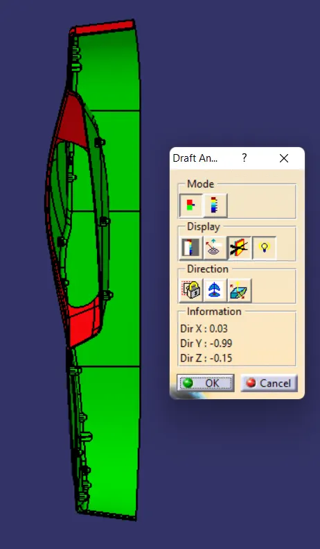
Figure: Top View of Draft analysis on the Final part body
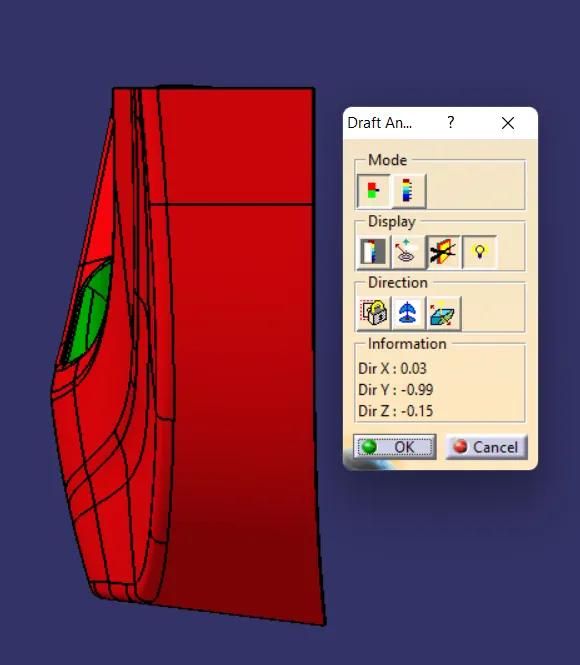
Figure: Front View of Draft analysis on the final Closed body
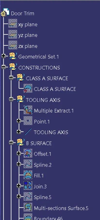
Figure: Exapnded Tree-1
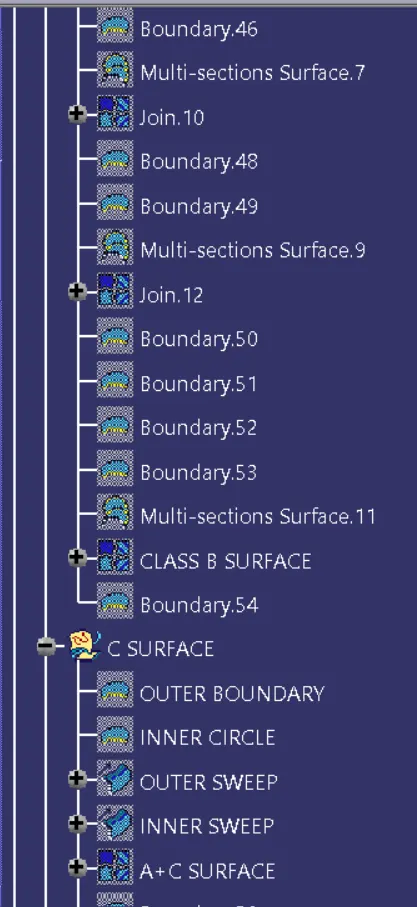
Figure: Expanded Tree - 2
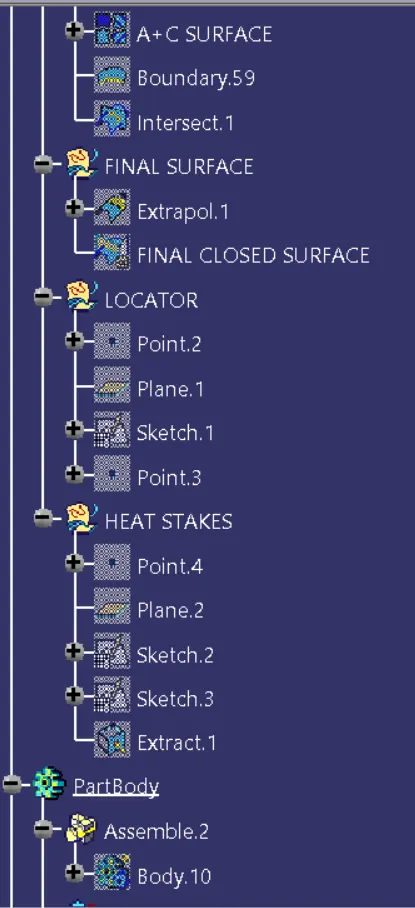
Figure: Expanded Tree -3
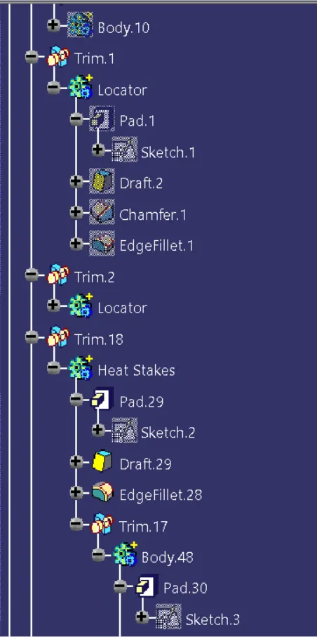
Figure: Expanded Tree -4
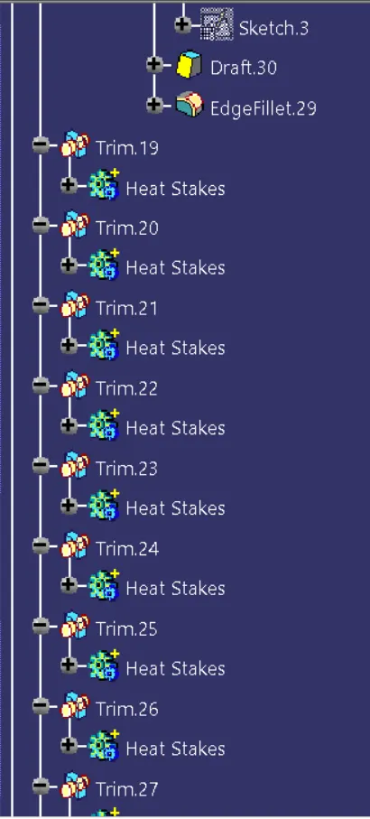
Figure: Expanded Tree - 5
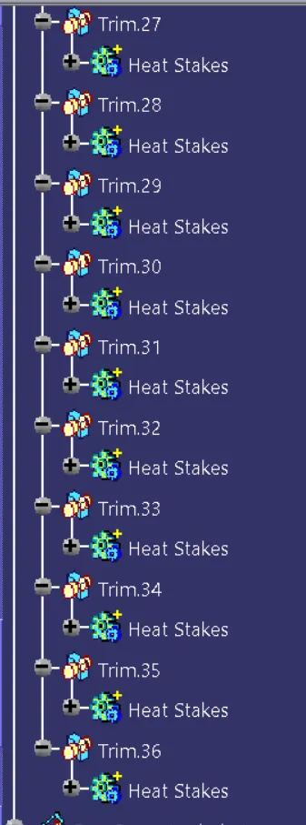
Figure: Expanded Tree - 6
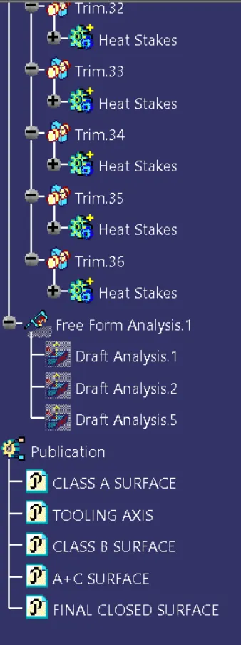
Figure: Expanded Tree -7