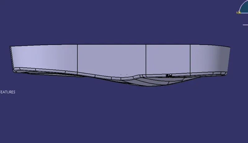
Week 9 - Project 1 - Door Trim Lower with Engineering Features
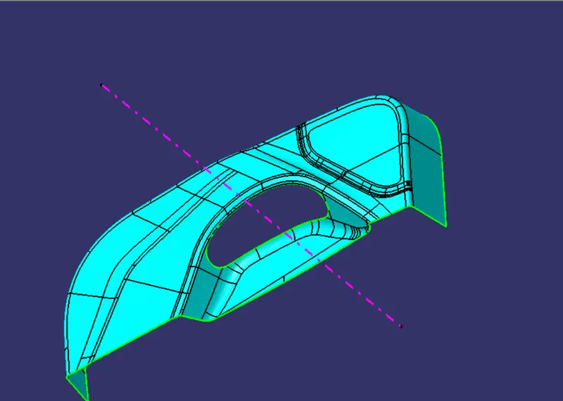
CREATION OF MAIN TOOLING AXIS :
POINT AND DIRECTION METHOD
STEP FOLLOWED :
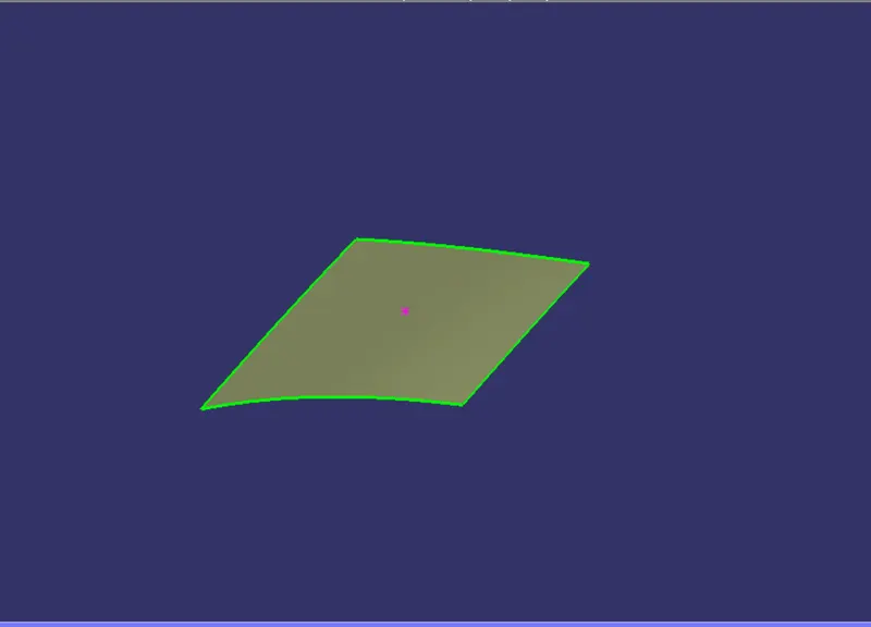
1) Extract a surface from class-A surface which is almost straight and almost at middle of class-A surface, most
of the part of class-A surface should visible from it's top view.
2) Create a point on that surface
3) Create a line from that point in appropriate tooling direction
4) Above found line will be the desired main toooling axis, now we can change it's propertis

DRAFT ANALYSIS :
DRAFT ANALYSIS FOR CLASS-A SURFACE
STEP FOLLOWED :
1) Create main tooling axis
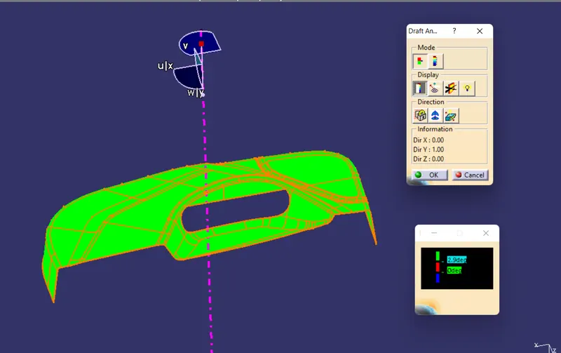
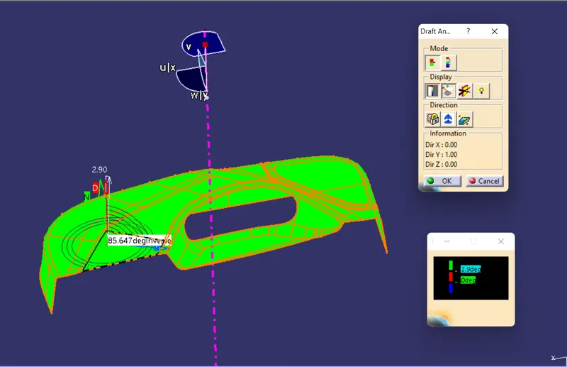
2) Pic the draft analysis tool, select the part ( class-A surface ), set the value of angle in which we have check the draft angle
3) Here for the Class-A surface and complete part body the minimum draft angle is 3 degree and for the B-side attachement feature the minimum draft angle is 1 degree
4) Drag the compass into main tooling axis,activate it and recheck it's position
5) Now we can perform the draft analysis in various mode such as Quick Analysis mode, full analysis mode, and analysis under running point
Quick analysis mode
Analysis under running point
DRAFT ANALYSIS FOR COMPLETE PART BODY
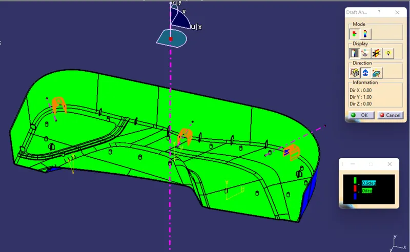
For the internal part of dog house we have need to provide a saparate side core , Hence the draft analysis of that portion performed with respect to the saparete side core axis. The individual side core axis for each dog house is shown in the part as well as in design tree under manufacturing requirements.
VARIOUS ORIENTATION OF PART :
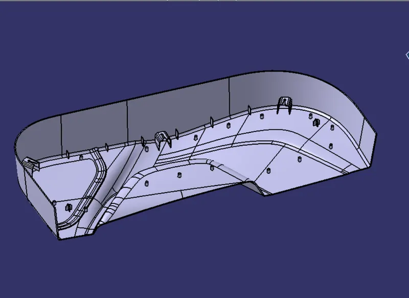
ISOMETRIC VIEW :
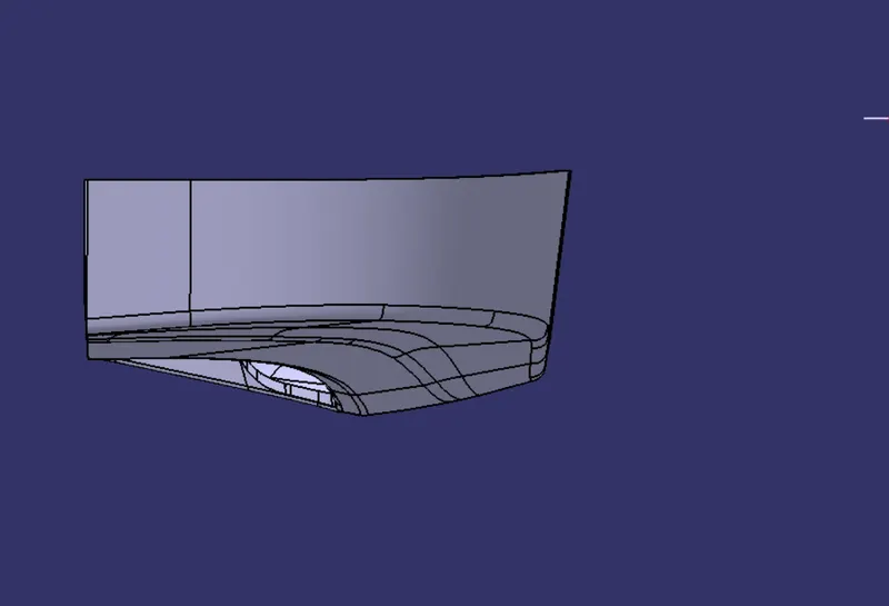
FRONT VIEW :
TOP VIEW :
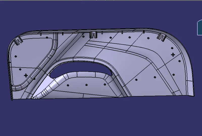
SIDE VIEW :