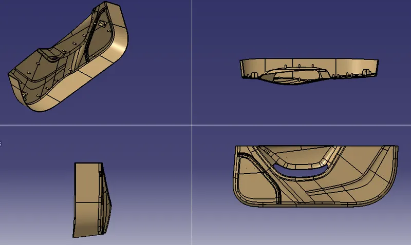
Week 9 - Project 1 - Door Trim Lower with Engineering Features
AIM -Create the Door Trim Plastic component through the given Class-A surface.
CLASS A SURFACE
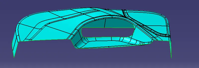
STEP 1 - Check the connectivity/continuity of the surface using the boundary tool or the close surface tool.
Step 2 - Creating TOOLING AXIS
- Check the best tooling direction by visualy considering the cost factor in mind. Here the best tooling direction is Y direction because other two direction are problem making complex.
- Etract the base and a point was created at the center of the extract.
- Using the axis system and point we create a line in y direction. And that is our tooling axis.
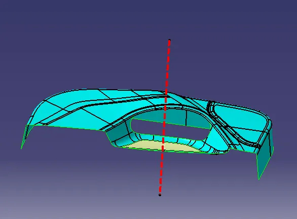
[ TOOLING AXIS - The direction in which mold open and close or simply say that tool movement axis.It decide the draft direction]
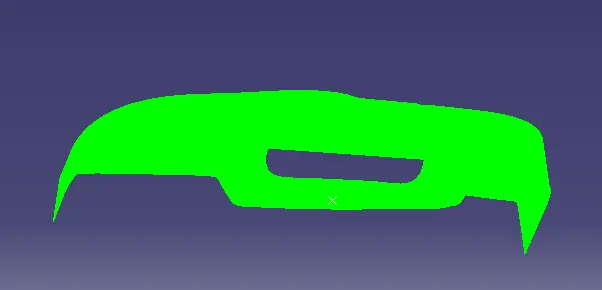
STEP 3 - DRAFT ANALYSIS for CLASS A
- Here the given class A surface is subjected to the daft analysis with draft angle 3 degree.
- From insert the draft analysis tool is taken, here we placing the compass to the tooling axis.
- Click on the class A, then we get a green colour on top and blue in the bottom. It means that draft angle decreasing from 3 degree to 0 degree.
Step 4 - Creating the CLASS B surface.
- Extracting the surfaces from class A.
- Using the trim,multiple extraction,extrapolate and joining commands ,then we got a Class B surface that is 2.5mm below the CLASS A
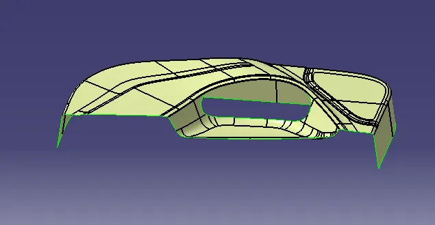
Step 5 - Creating the CLASS C surface.
- By using the sweep and tooling axis we got the CLASS C SURFACE.
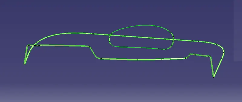
STEP 6 -
- Joing class A Surface and C Surface
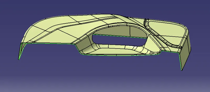
STEP 7 - CLOSED SURFACE
- Trim the surafce with CLASS B Surfcae
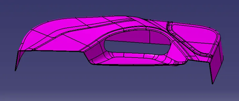
STEP 8 - Creating solid from closed surface
- Using the Close surface tool in part workbench.
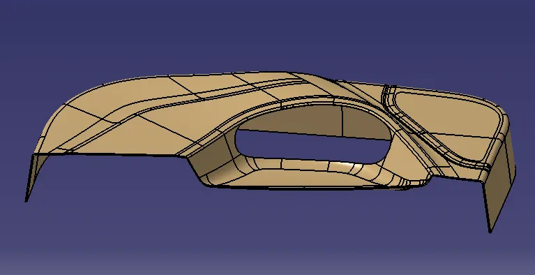
STEP 9 - Draft Analysis for Part
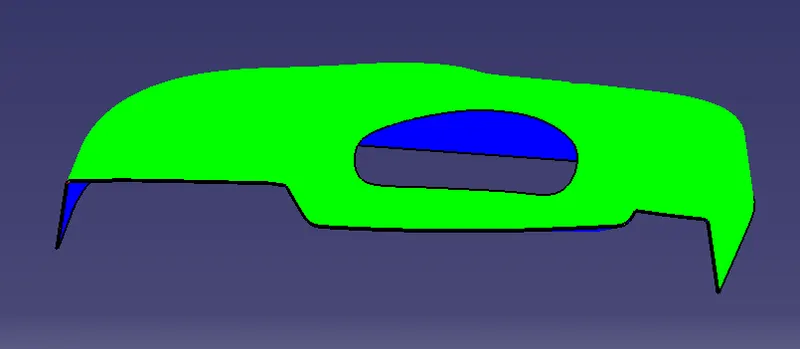
- Here the part subjected to the daft analysis with draft angle 3 degree.
- From insert the draft analysis tool is taken, here we placing the compass to the tooling axis.
- Click on the part, then we get a green colour on top and blue in the bottom. It means that draft angle decreasing from 3 degree to 0 degree.
B SIDE FEATURE CREATION
1) HEAT STAKES
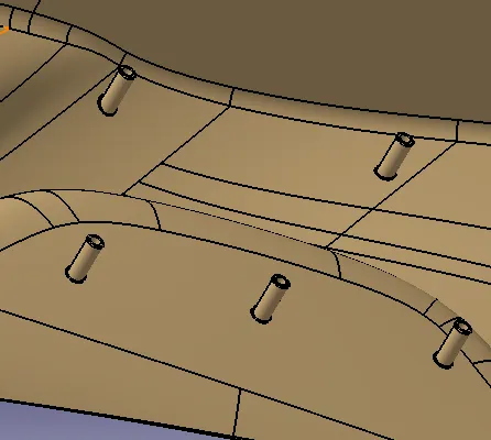
- The heat stakes are placed in the b side side of the part and here we place 16 heat stakes in the different positions on the B side.
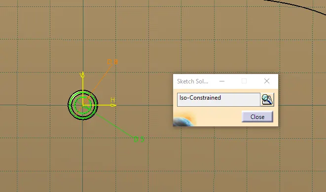
- The heat stakes has a inner diameter of 5mm and the outer diameter of 7 mm is created by using sketch and pad option. It is pad to 20mm above and 6 mm beow.
- After the pad we use union trim to attach the heat stakes to the door trim part and after we filleted and drafted.
- The sketch of the heat stake is given below.
LOCATORS
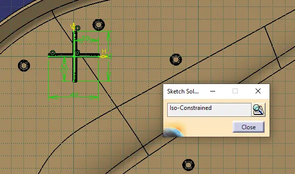
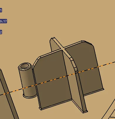
- The Locators are placed in the B side side of the part and here we place two 4 way Locators in the different positions on the B side.
- Using the sketch and pad pad option we create the locators in the different position of the b side and also provided the minimum draft and the fillets.
- After we added the locators to the main door trim part.
- The sketch is shown in below ,
DRAFT ANALYSIS OF THE DOOR TRIM WITH HEAT STAKES AND LOCATORS
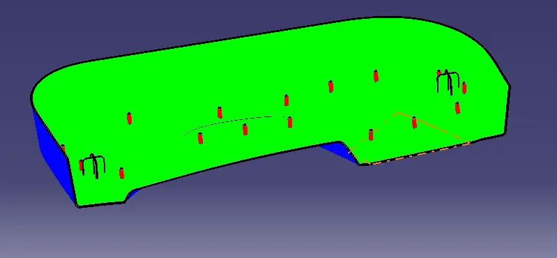
- Here the final part eith the heat stakes and locator is subjected to the daft analysis with draft angle 0.5 degree.
- From insert the draft analysis tool is taken, here we placing the compass to the tooling axis.
- Click on the part, then we get a green colour on top and blue in the bottom except the heat stakes area.
- It means the heat stakes are not cleared using the 0.5 degree draf angle.
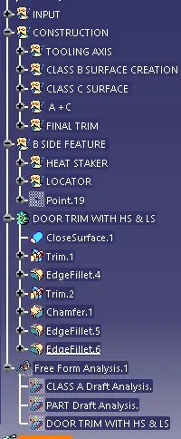
TREE STRUCTURE
Screenshots of the completed design in various orientations