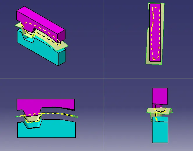
Week 8 - Challenge 6 - Core & Cavity Design
AIM - Create the Core and cavity blocks for the switch bezel Plastic component.
CLASS A SURFACE
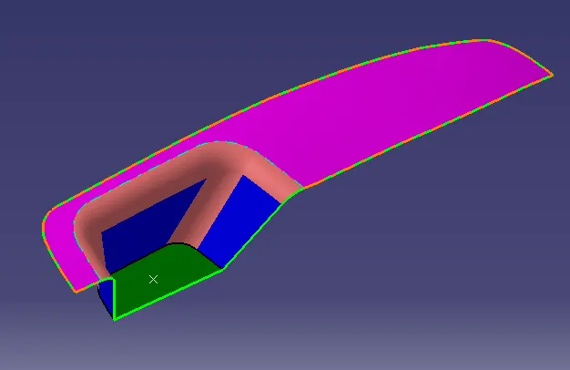
STEP 1 - Check the connectivity/continuity of the surface using the boundary tool or the close surface tool.
Step 2 - Creating TOOLING AXIS
- Check the best tooling direction by visualy considering the cost factor in mind. Here the best tooling direction is Z direction because other two direction are problem making surafces.
- A point was created at the center of the base, Using that axis system is inserted. For tooling axis we create the two sketch line with respect to the surface.
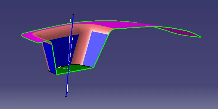
- Creating the TOOLING AXIS by bisecting the two sketches. And the result is the tooling axis (blue colour line ).
[ TOOLING AXIS - The direction in which mold open and close or simply say that tool movement axis.It decide the draft direction]
STEP 3 - DRAFT ANALYSIS for CLASS A
- Here the draft angle is 2 degree,if we give 3 degree it shows red colour in the side wall.
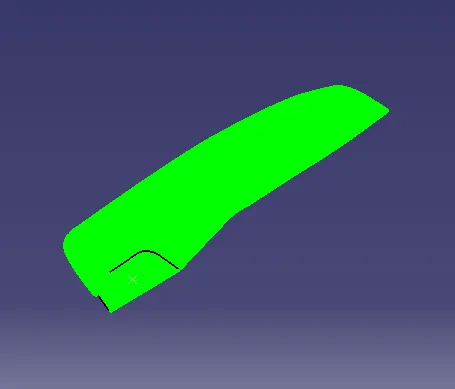
Step 4 - Creating the CLASS B surface.
- Extracting the surfaces from class A ,then Untrim and Extrapolate
- Offsetting the extrapolated surfaces and trim the offseted surfaces , then we got a Class B surface that is 3 mm below the CLASS A
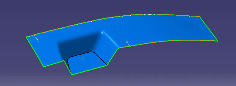
Step 5 - Creating the CLASS C surface.
- By using the sweep and tooling axis we got the CLASS C SURFACE.
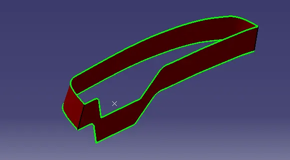
STEP 6 -
- Joing class A Surface and C Surface
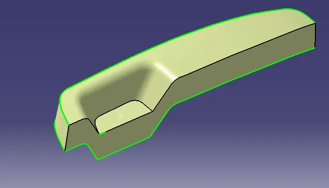
STEP 7 - CLOSED SURFACE
- Trim the final joined surafce with CLASS B Surfcae
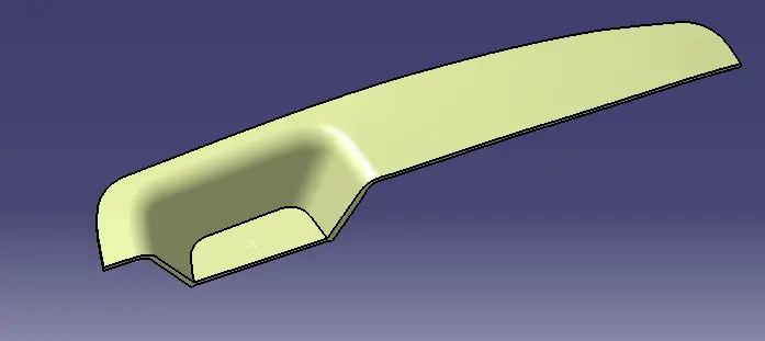
STEP 8 - Creating solid from closed surface
- Using the Close surface tool in part workbench.
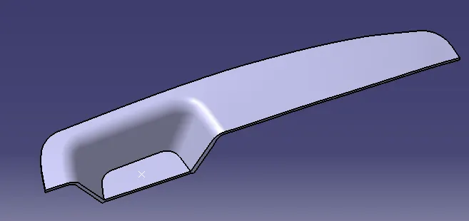
STEP 9 - Draft Analysis for Part
- Here the draft angle is reduced to 0.5degree for better drafting. But in the one edge of the part showing red colour due to some software version problem.
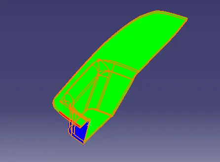
CORE ,CAVITY ,PARTING SURFACE AND PARTING LINE
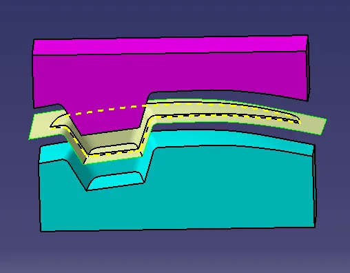
PARTING SURFACE
Generally injection mold has two major components : the movable half and the fixed half, during the injecction molding process, these two halves are pressed tightly from a sealed hollow to avoid the melt flow leakage and maintain certain holding pressure, the pressed surface are called parting surface , usually parting surface are the biggest projection outline of the part.
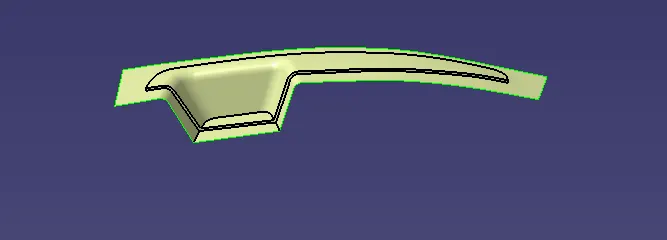
PARTIN LINE
A parting line is an inevitable part of injection molded products. It is the line of separation between where two halves of a mold meet.
EXAMPLE - If we look to the pen body there is line in thed middle, that is parting line.
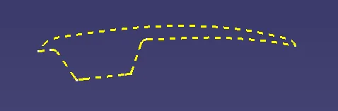
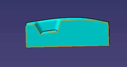
CAVITY & CAVITY
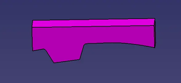
CAVITY
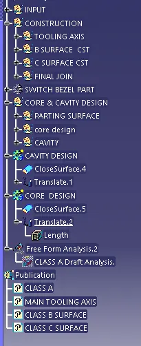
TREE STRUCTURE
Screenshots of the core and cavity blocks in various orientations