Week 8 - Challenge 2 - Switch Bezel Design
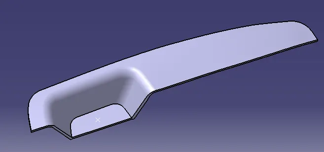
AIM - Create the Switch Bezel Plastic component through the given Class-A surface.
CLASS A SURFACE
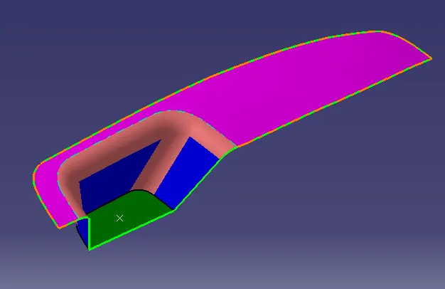
STEP 1 - Check the connectivity/continuity of the surface using the boundary tool or the close surface tool.
Step 2 - Creating TOOLING AXIS
- Check the best tooling direction by visualy considering the cost factor in mind. Here the best tooling direction is Z direction because other two direction are problem making surafces.
- A point was created at the center of the base, Using that axis system is inserted. For tooling axis we create the two sketch line with respect to the surface.
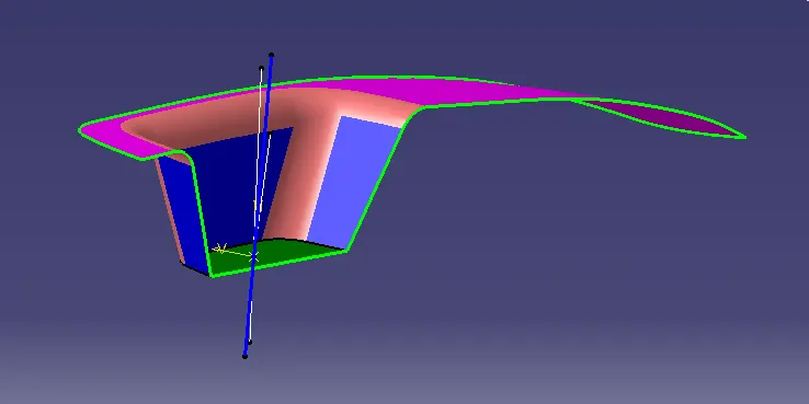
- Creating the TOOLING AXIS by bisecting the two sketches. And the result is the tooling axis (blue colour line ).
[ TOOLING AXIS - The direction in which mold open and close or simply say that tool movement axis.It decide the draft direction]
STEP 3 - DRAFT ANALYSIS for CLASS A
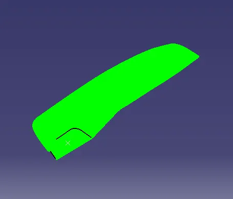
- Here the draft angle is 2 degree,if we give 3 degree it shows red colour in the side wall.
Step 4 - Creating the CLASS B surface.
- Extracting the surfaces from class A ,then Untrim and Extrapolate
- Offsetting the extrapolated surfaces and trim the offseted surfaces , then we got a Class B surface that is 3 mm below the CLASS A
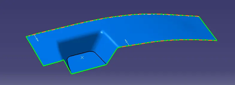
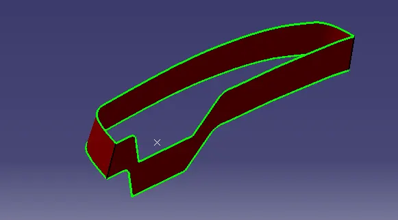
Step 4 - Creating the CLASS C surface.
- By using the sweep and tooling axis we got the CLASS C SURFACE.
STEP 5 -
- Joing class A Surface and C Surface
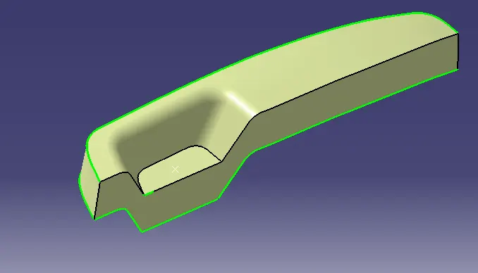
STEP 6 - CLOSED SURFACE
- Trim the final joined surafce with CLASS B Surfcae
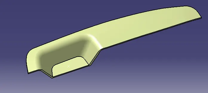
STEP 7 - Creating solid from closed surface
- Using the Close surface tool in part workbench.
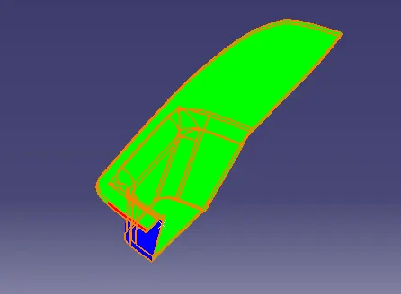
STEP 8 - Draft Analysis for Part
- Here the draft angle is reduced to 0.5degree for better drafting. But in the one edge of the part showing red colour due to some software version problem.
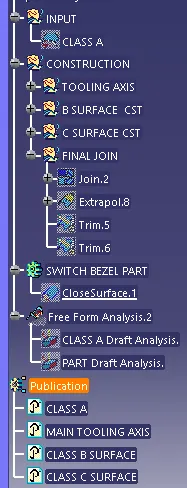
TREE STRUCTURE