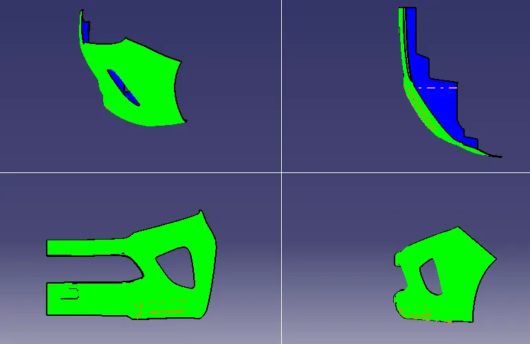
Week 8 - Challenge 4 - Bumper
AIM - Create the Bumper Plastic component through the given Class-A surface.
INPUT - CLASS A SURFACE
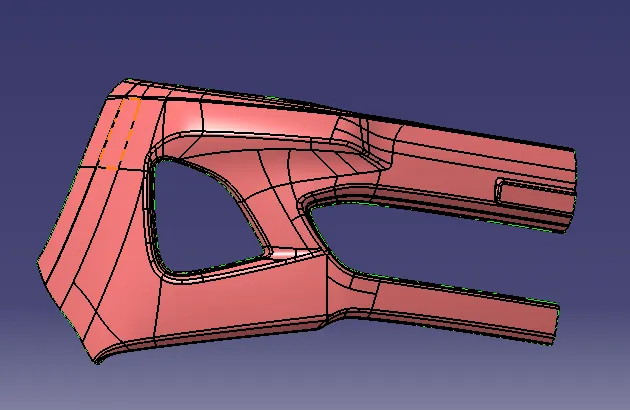
STEP 1 - TOOLING AXIS
- For creating tooling axis , first we understand the class A from three direction (x,y,z).
- Here we can able to see more places of the class A ,so we make the tooling axis in the x direction.
- It is checked with the draft analysis.
- If any issue in the analysis we make another tooling axis.
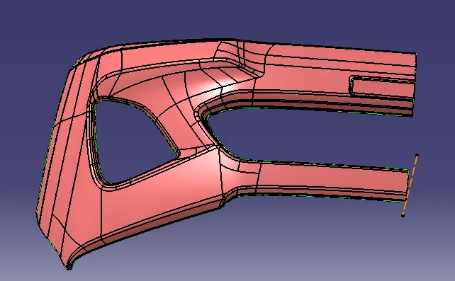
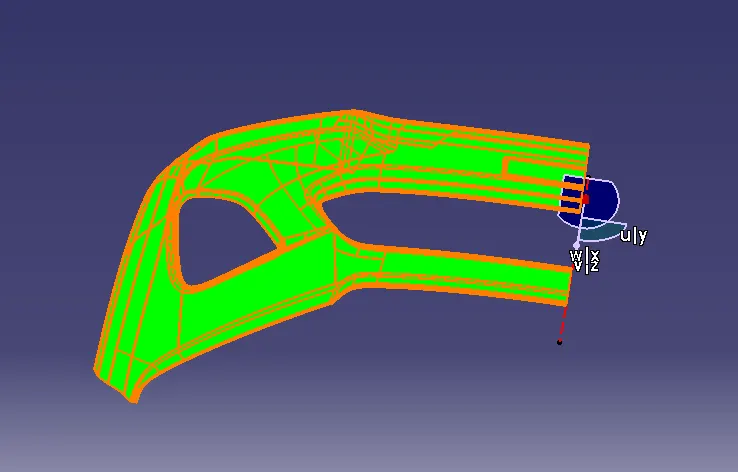
STEP 2- DRAFT ANALYSIS OF GIVEN CLASS A SURFACE
- Here the given class A surface is subjected to the daft analysis with draft angle 3 degree.
- From insert the draft analysis tool is taken, here we placing the compass to the tooling axis.
- Click on the class A, then we get a green colour on top and blue in the bottom. It means that draft angle decreasing from 3 degree to 0 degree.
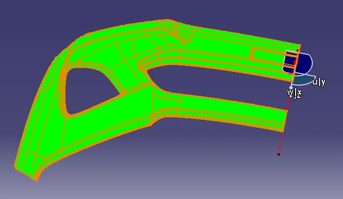
STEP 3 - CLASS B SURFACE CREATION
- First we offset the class A to 2.5mm ,here we got some issue in the offset surface.
- We get the Class B surface by doing operation like Extract, Extrapolate ,Join, Trim,Untrim etc..
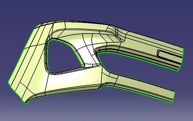
SREP 4 - CLASS C SURFACE
- Using the boundary and sweep command we got the Class C surface.
- Sweep command is use with the reference surface.
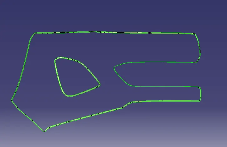
STEP 5 - Join the class A with the class C surface
- For this i used the extrapolate and trim option to joining the surfaces
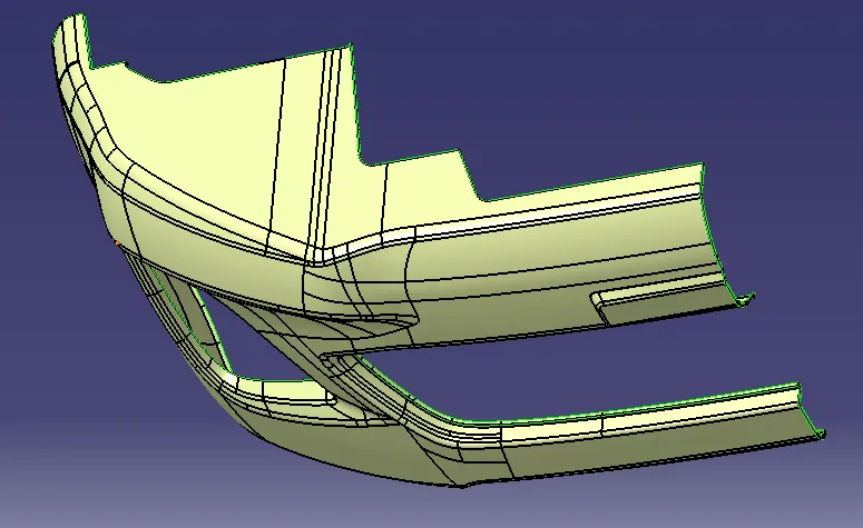
STEP 6 - BUMPER SURFACE
- Trim the step five result with the class B surface.
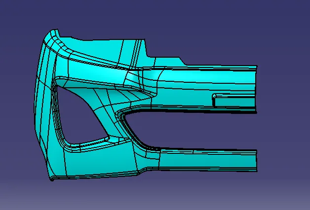
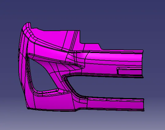
STEP 7 - BUMPER PART
- BUMPER PART is created by using the close surface tool in the part workbench.
STEP 8- DRAFT ANALYSIS OF THE PART
- The procedure is same as the class A analysis and the draft angle is 3.
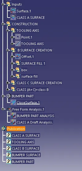
TREE STRUCTURE
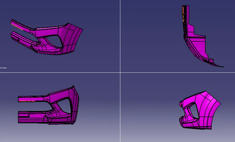
Screenshots of the solid model in various orientations
Screenshots of the solid model with the proper color code of the draft angle in various orientations