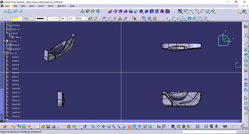
Week 9 - Project 1 - Door Trim Lower with Engineering Features
DOOR TRIM LOWER WITH ENGINEERING FEATURES:
OBJECTIVE:
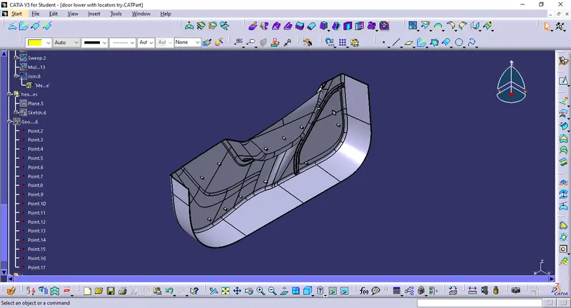
Design door trim and the other engineering features like heat stakes and locators. Create class B surface and class C surface, tooling axis. Convert into close body with the thickness of 2.5mm. Perform draft analysis on the final components.
DESIGN PROCEDURE:
TOOLING AXIS:
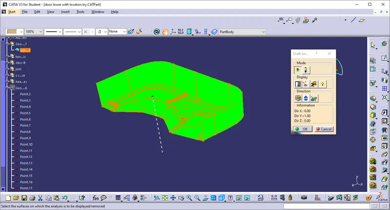
First create tooling axis either with any method, bisection method or normal to surface method, In bisection method we take the intersection of the CLASS A surface, draw an imaginery tooling axis and the supporting lines, then a bisecting line is created and named as tooling axis, Normal to sufrace is the method choosen for this design. Choose a surface and then locate a point on the surface, then insert an axis system to the point. Draw a line normal to the surface from point. Perform draft analysis to check the quality of CLASS A surface.
CLASS B SURFACE DESIGN PROCEDURE:
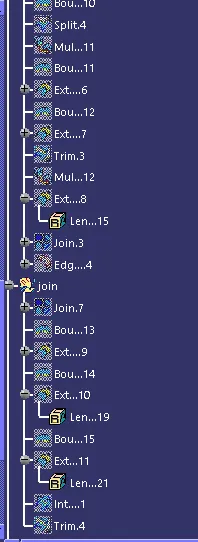
Class B sufface is designes by using simple offset method. Select the class A and then use offset to offset the surface to 2.5mm which is the thickness of the component. While formation of the offset most of the times the areas with fillets are hard to form as a result for the regions with fillets or complex curvatures gaps are formed. The chance for this to happened is less while we are workin on the updated version of the tool.
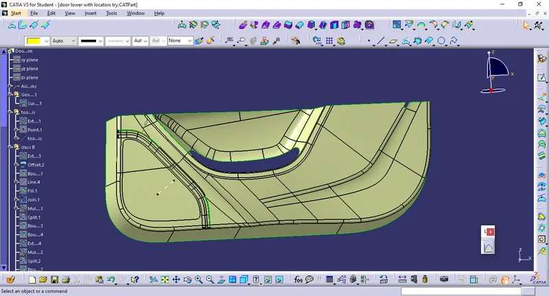
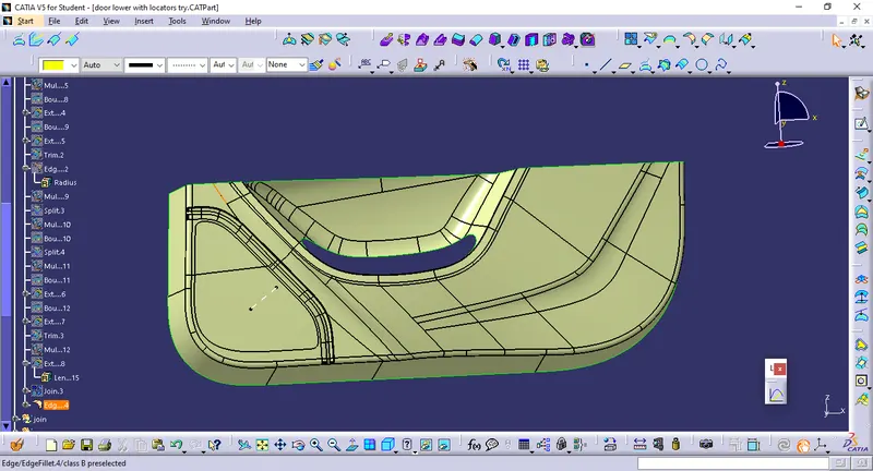
Work on the patches saperately by using extract sufaces, extapolating the surfaces and then trim, give the fillets at the required edges, generally we can also fill the gaps using multisection and blend, if in case due to requirment if are to make make any changes to fillets in the design it is really hard to make changes if multisection and blend are used, ot is easy to alter fillets if extract-extrapolate-trim-fillet procedure is used.
DESIGN PROCEDURE FOR CLASS C SURFACE:
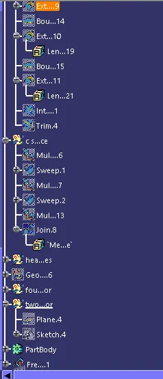
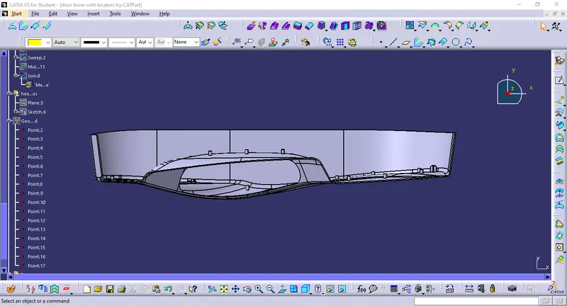
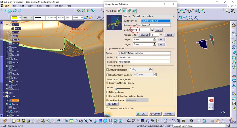
Hide the B surface when it is done, unhide the class A surface as C surface is created with respect to CLASS A. Extract the boundary of the class A surface ,use swept surface defination and select the sweep w.r.t referance surface, set the angle to 93 degress as 3 degress of draft is required to facilitate easy ejection.
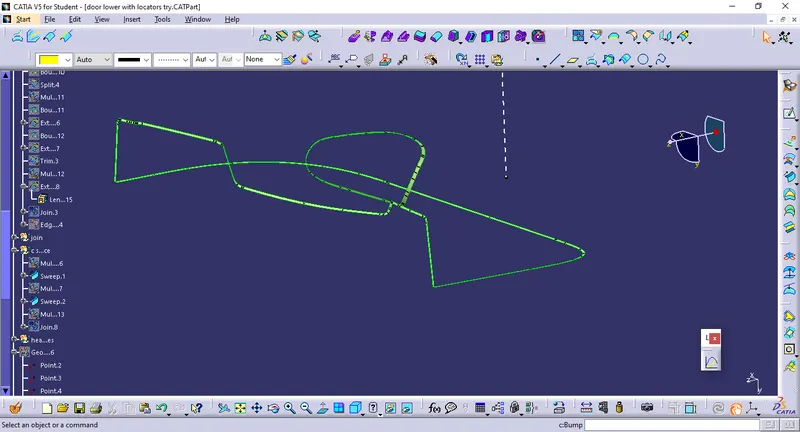
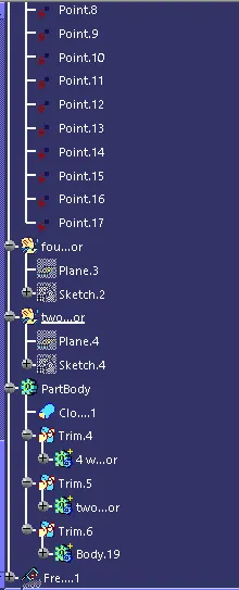
Join Class A and Class C surface, by suing join, now use the A+C sufrace and trim it with the B surface, select sufrace boundary, and then select the final trim, this should reflect error this is onw way of checking if the surfaces are closed properly. Then move to part body workbench and use closed surface to form solid body.
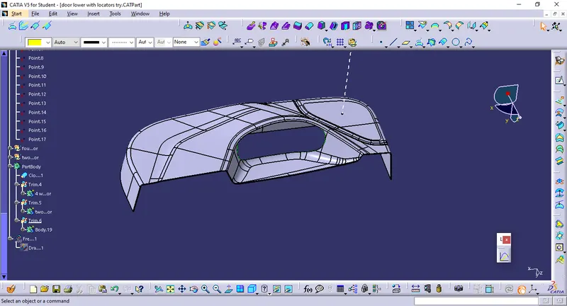
LOCATORS:
A 2-way locating pin restricts motion along 1 axis (or 2 degrees of Freedom), like a round pin in a slot. Likewise, a 4-way pin restricts 4 degrees of freedom along 2 axes. A round locating pin located concentrically in a hole is a common application of a 4-way pin, and helps to further secure the piece.
HEAT STAKING:
Heat staking also known as thermoplastic staking is the process of joining two dissimilar materials together. In heat staking we use local heating and cooling to raise the temperature of plastic components and allow plastic reforming to be carried out. This reforming can be used in a wide variety of applications.
DESIGN PROCEDURE:
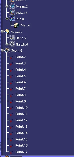
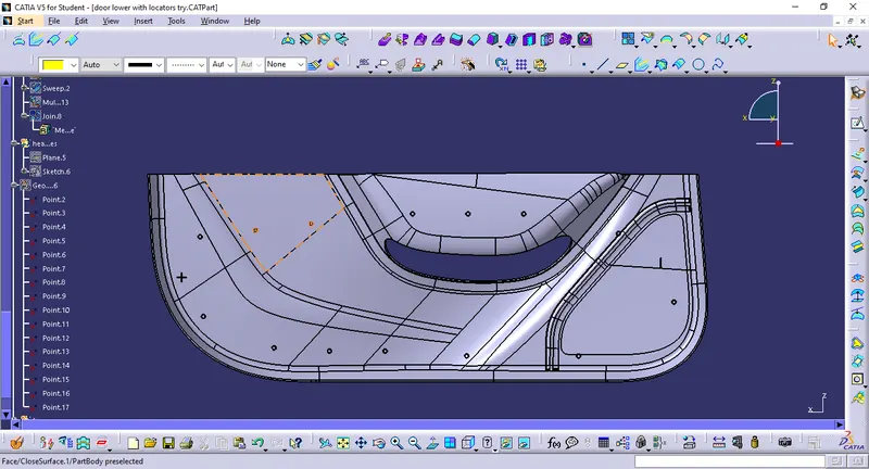
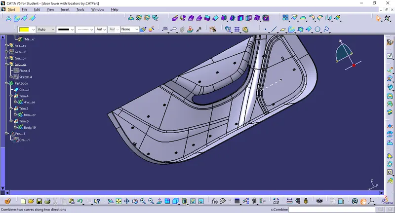
Points are necessary to easily create locators and heat stakes on the part, Take the boundary of the class A surface then using parallel curve offset the boundary inwards, use pattern to create points with referance to the curve, hide the curve.
Inset a new plane parallel to point and selecting referance as yZ plane.
Draw a sketch for the four way locator and then shift to part design workbench and use pad and thicken option. Give the draft of .5 degress to the faces of locaters by choosing axis as pulling direction.
Fillet the edges then use assemble or union trim with part body.
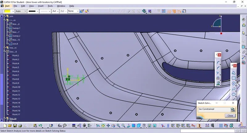
Similarly design two way locater at the opposite side of the door trim.
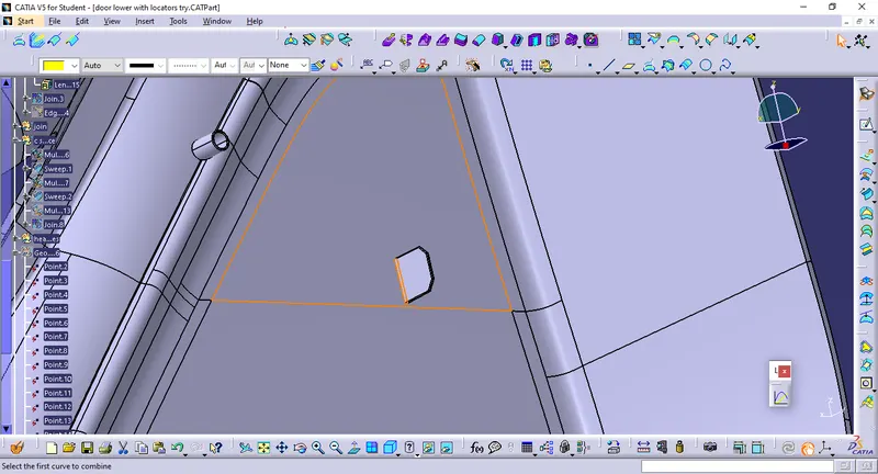
To design heat stakes we eill design one with proper draft and then translate using poin to point option.
First select the plane and use poin projection sketch to draw circles with dia 7mm and 5mm, use pad to extrude the sketch, using draft give draft of 0.5 degrees. Give fillet of 0.3mm at the edges, copy and past special keeping the link and then translate the heat stakes by using poin to point.
DRAFT ANALYSIS:
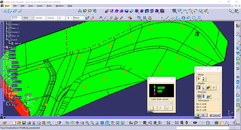
DRAFT ANGLE 2.9degrees
Even after maintaining the draft of 3 degrees there are still few areas which are unable to create draft analysis, this is due to the complexity of class A surface and this is a rare case where part of class C sufrace is fotmed in cavity as we place the component in the view of tooling direction the downward portion of the class C is not visible and is flat so it has to be created along B surface .
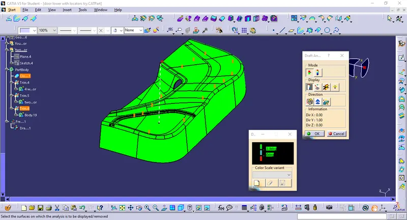
Draft analysis for features:
Draft angle of 0.49 degrees