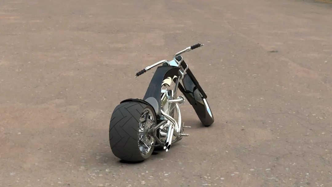
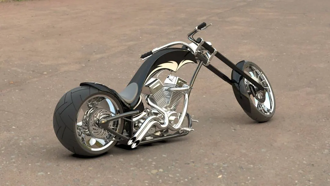
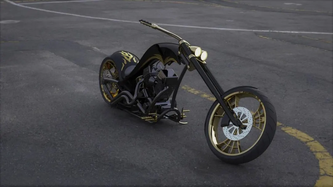
Photo Realistic Rendering
Chopper design and assembly:
The chopper is perhaps the most extreme of all custom styles, often using radically modified steering angles and lengthened forks foe stretched-out appearance.They can be built from an original motorcycle ehich is modified(chopped) or buit from scratch. Some of the charcteristic features of choppers are long front ends with extended forks often coupled with an increased rake angle, Choppers tend to be based on traditional motorcycles or cruisers,which have different style from other bikes. Unlike sports bikes, where the rider leans forward, choppers are usually designed so that the rider sits low in the seat, leaning back ,arms outstretched. This provide a relaxed riding experience.
Objectives:
The design of the chopper gives us decent challenges and involves use of overall all the important tools and commands in solidworks. We wioll design the parts of the chopper induvidually and assemble them.Our chopper design has the following parts.
- Transmission belt
- Kick stand
- Front fender
- Rare fender
- Oiltank
- Chain
- Pedal
- Front wheel
- Rare wheel
- Front fork
- Chassis
- Engine
- Gas tank
Transmission belt:
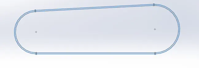
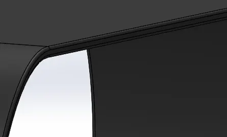
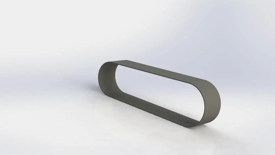
It involves very basics of solidworks like drawing lines,circles, assigning relations,power trim and offset. We will draw a sketch usinh line, circle and few tagent relations.Sketching with proper dimensions and relations will fully define the sketch. We will use extrude feature and apply fillets to the edges.At last will will add appearance to the part.
Kick stand:
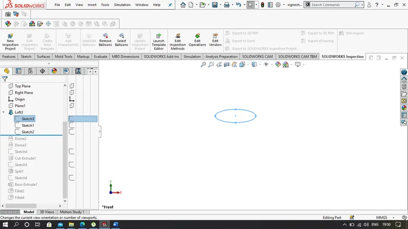
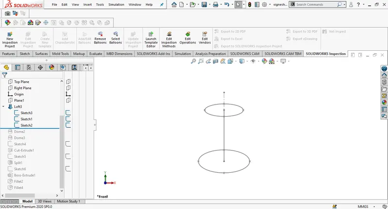
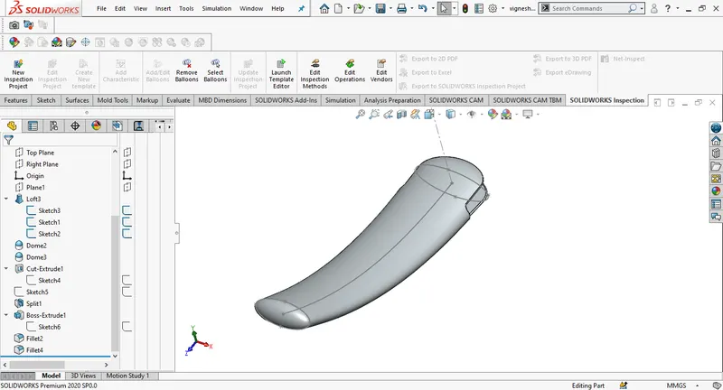
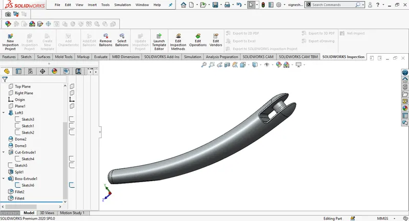
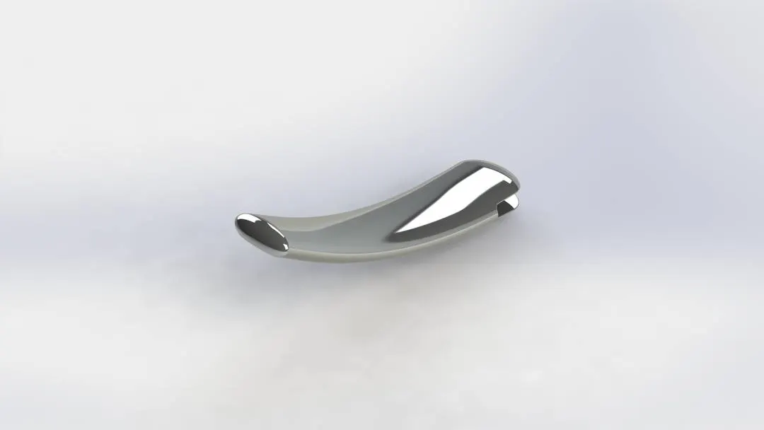
We design our kick stand by drawing an ellipse in the front plane from the origin with proper dimensions.By selecting the midplane we will draw a spline from thje origin, by using smart dimensions we will define the sketch. A new plane is created at the end of the spline and on the new plane an another ellipse is drawn and by using pierce relarion we will make the end of the spline and ellipse coincident. We have to loft between both the ellipses selecting both the ellipses and spline, this will allow loft to follow the direction of the curve. Using dome we can rounf the edges. A flat surface is required to ground the kickstand, we use split feature by selecting consume cut bodies. addind fillets and appearence will give us the final output.
Front fender:
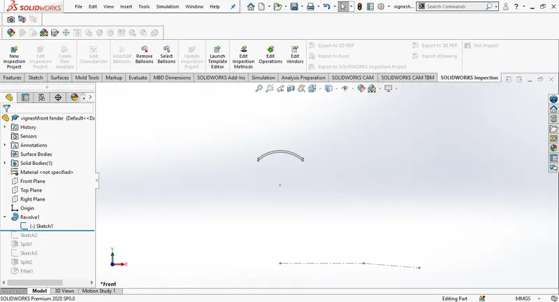
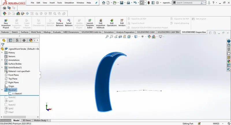
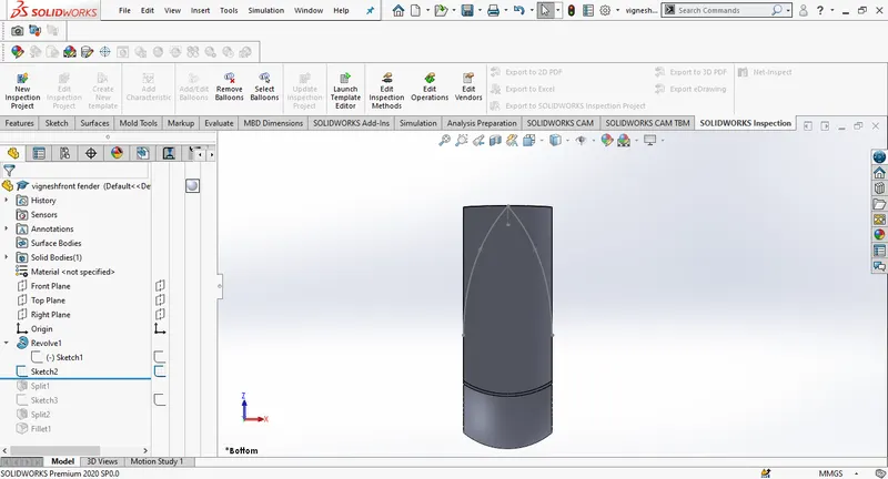
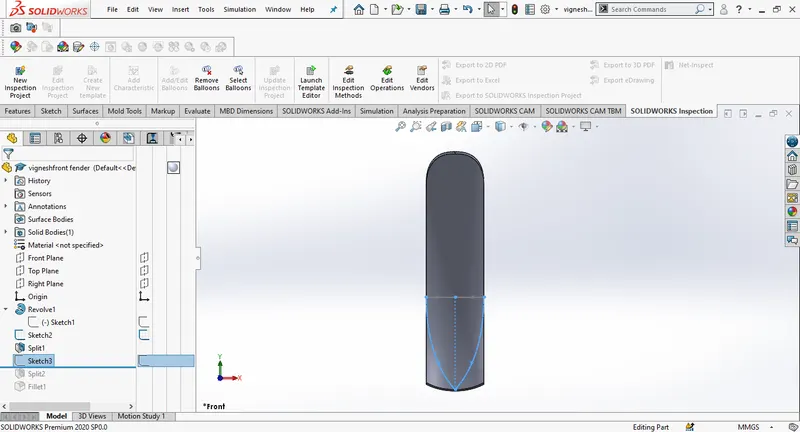
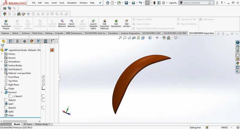
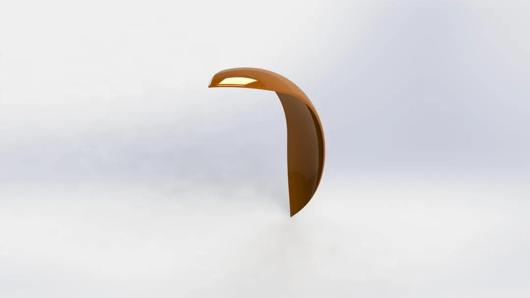
For the front fender of chopper we make use of revolved boss/base,split,shell. By selecting the front plane,using 3point arc and offset we can create a profile to use revolve boss feature.Two different sketches one in the top plane and the other in the right plane are sketched, using spilt and enabling consume cut bodies we can remove material from the fender. Using shell we can define thickness of the fender.
Rare fender:
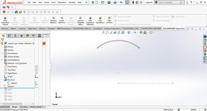
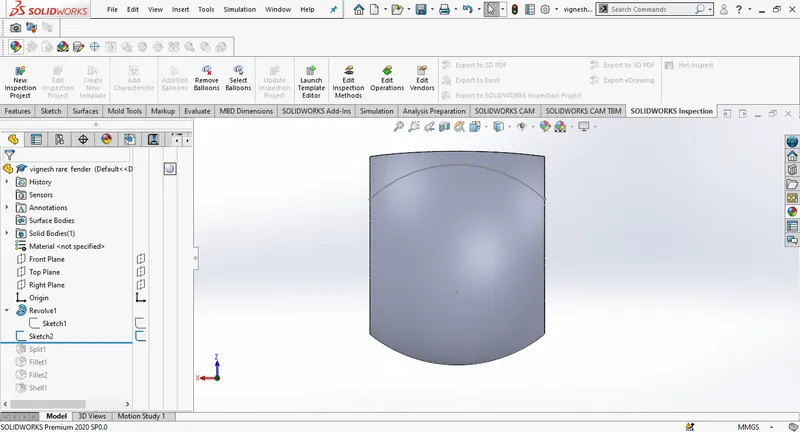
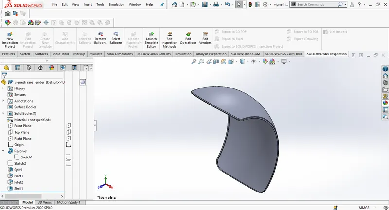
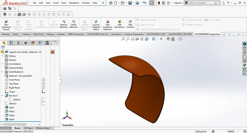
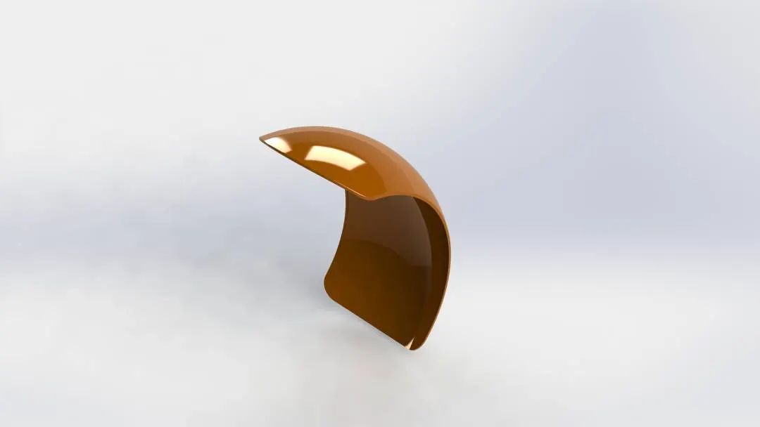
The design process for rare fender is same as the front fender except the sketch geometry.
Oil tank:
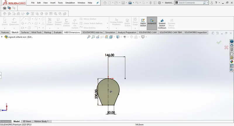
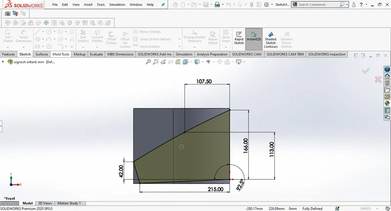
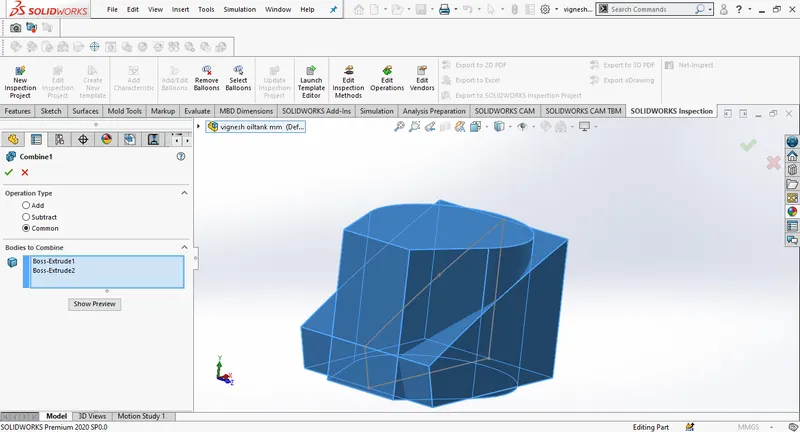
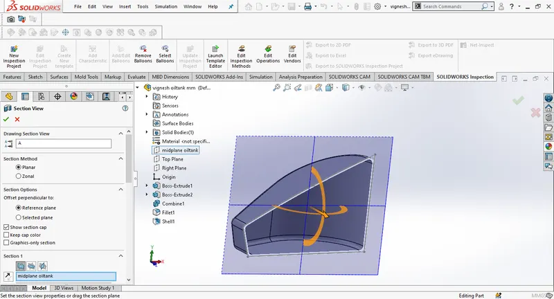
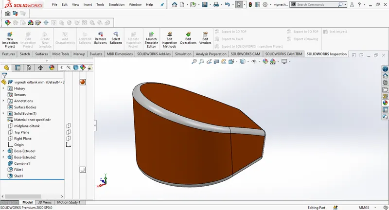
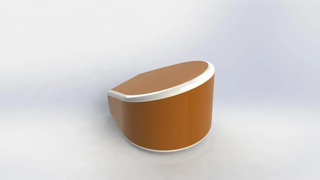
For the oil tank we firstly draw a sketch selecting the top plane using few lines, 3 point arc and tangent relations. We will extrude the sketch and in the front plane an another sketch is drawn and extruded by enabling the midplane extrude. Combine feature is used to combine both the extrudedd sketches. WE use shell to create the hollow space without affecting external geometry. Adding fillets and appearances will give us the final part.
Chain:
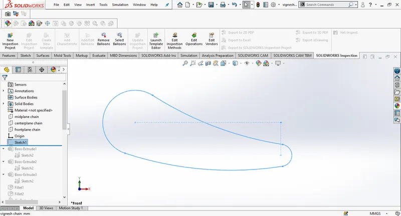
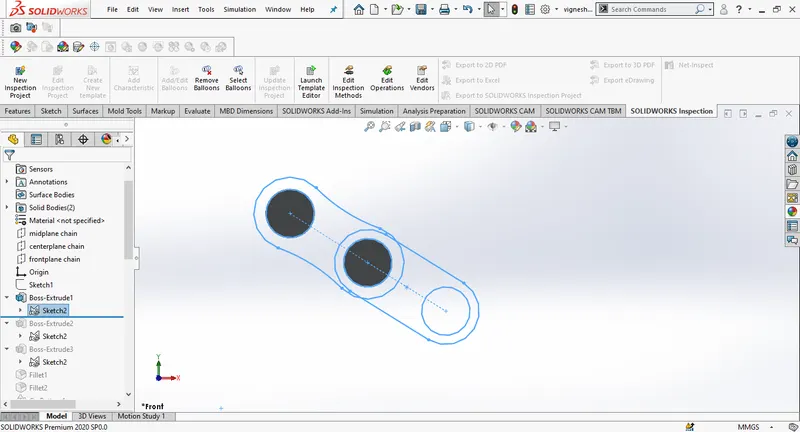
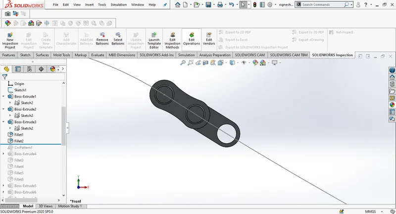
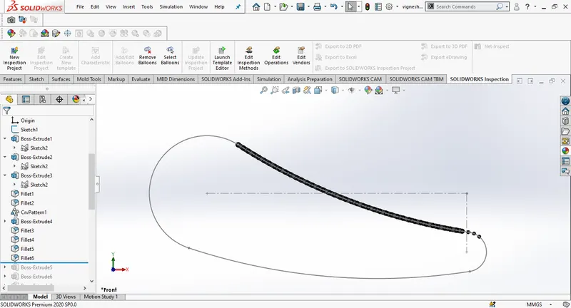
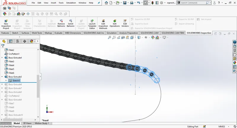
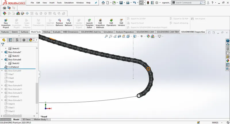
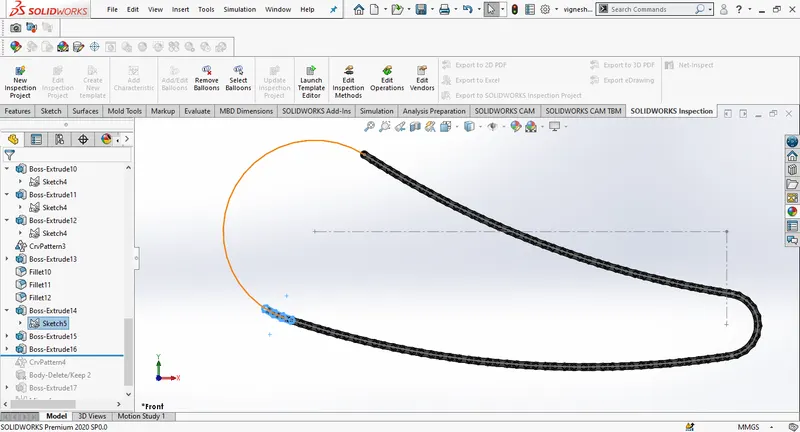
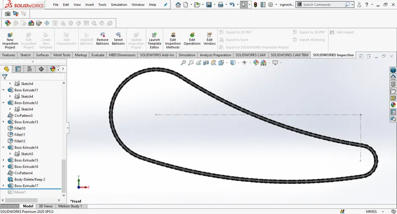
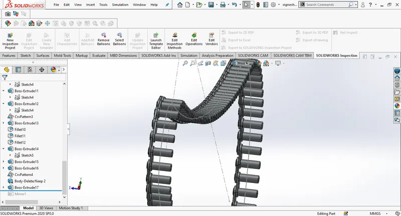
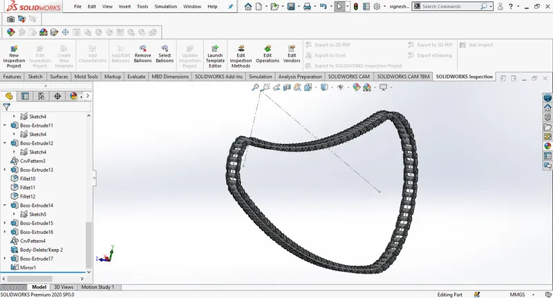
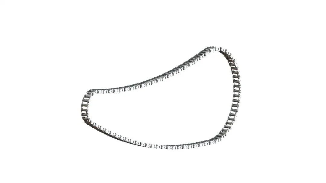
Designing of chain is a bit complicated and tricky, At first we will rename the planes, front plane as midplane chain, top plane as center plane and the right plane as front plane( It is not mandatory to rename the plane but renaming them can save ur time and give you a better understanding about the plane for the following part design). At first we will create a profile for chain using circles and three point arcs. A throwaway sketches are created for internal and external plates of the chain, then we save them and use it later. We will make pins to link the chain plates. Bring back the throwaway sketch by selecting insert blocks from the tools. The chain plates are alligned together with pins by enabling concentric and coincident relations. Using curve driven patter we can coplete the chain design but this may cause few distortions in the design so we break down the patterning by selecting the curves induvidually insted of selecting the entire sketch. Make sure that the fillets are applied to the pins before applying curve pattern. Now we have completed with only one half of the chain design we can simply mirror the chain plats across the midplane. Add appearance at the end to finish.
Pedal:
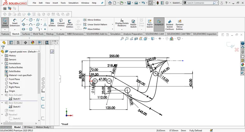
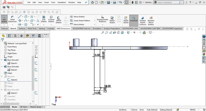
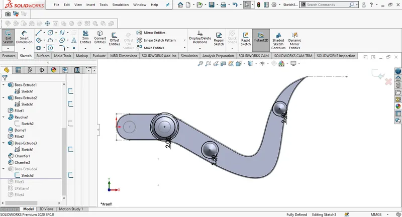
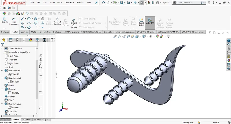
Firstly create a sketch on the front plane with proper dimensions and extrude the sketch, now we select the surface of the part as the sketch plane and draw a sketch for footrest and extrude it. We will provide some grip on the pedal by a new sketch and extrude. linear pattern is used to apply the extrude further. Finally we add fillets and the appearanc to the pedal. Here we are designing only the right pedal ,Left pedal is mirrored from the right.
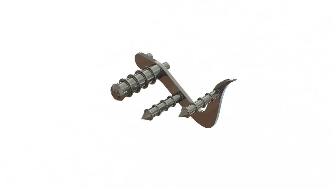
Front wheel:
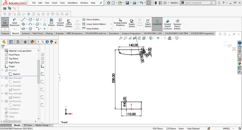
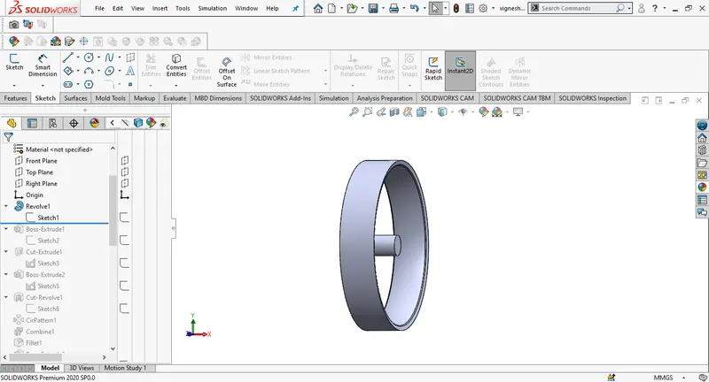
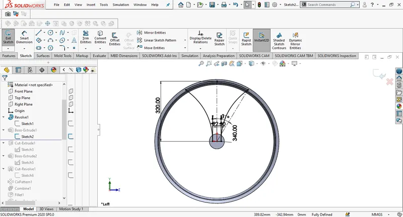
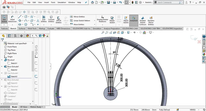
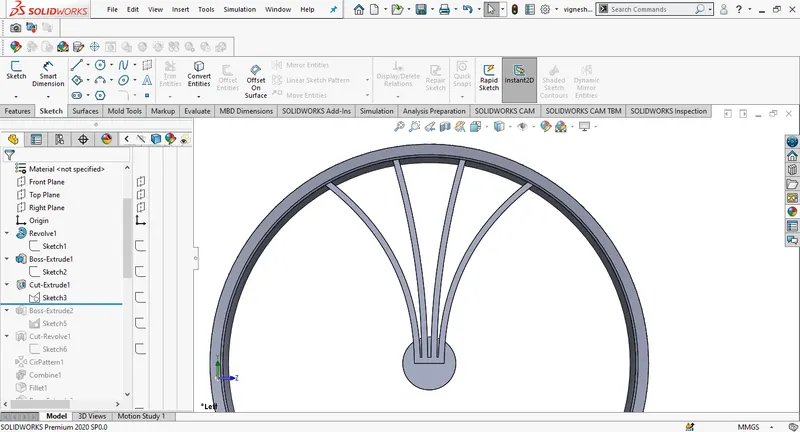
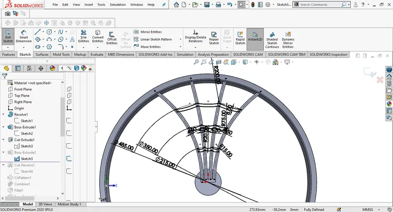
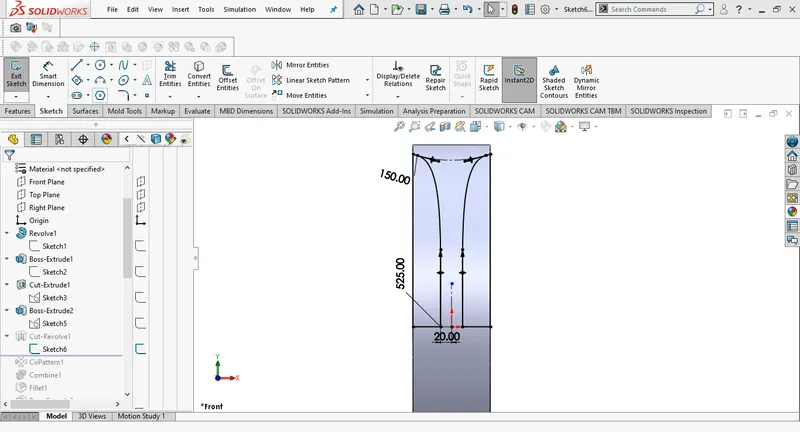
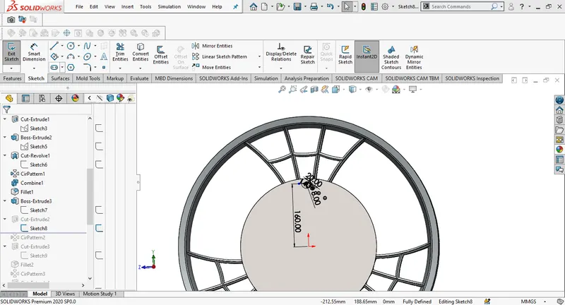
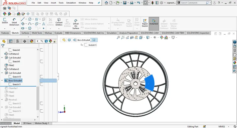
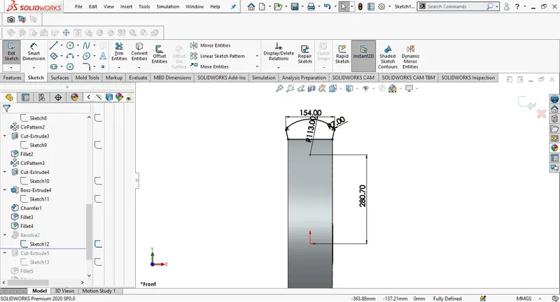
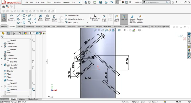
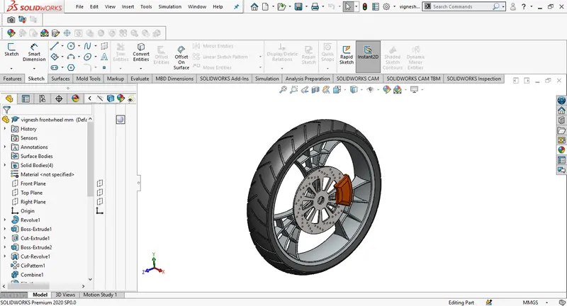
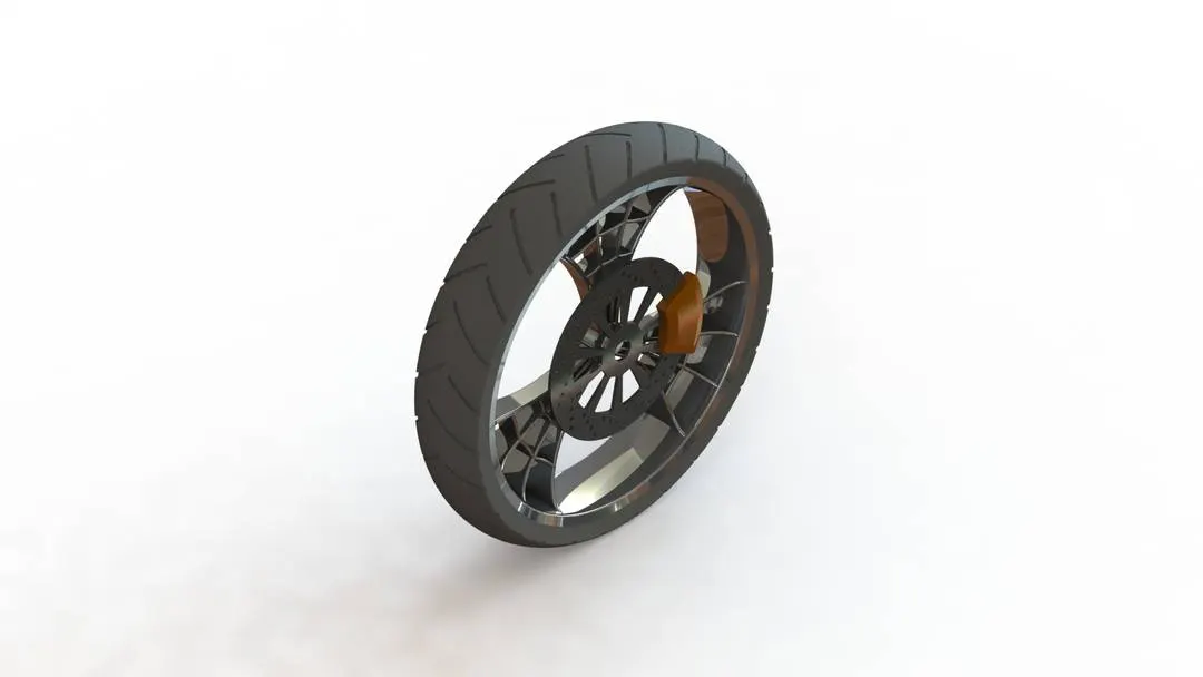
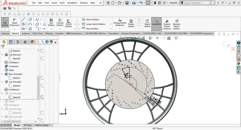
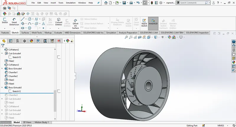
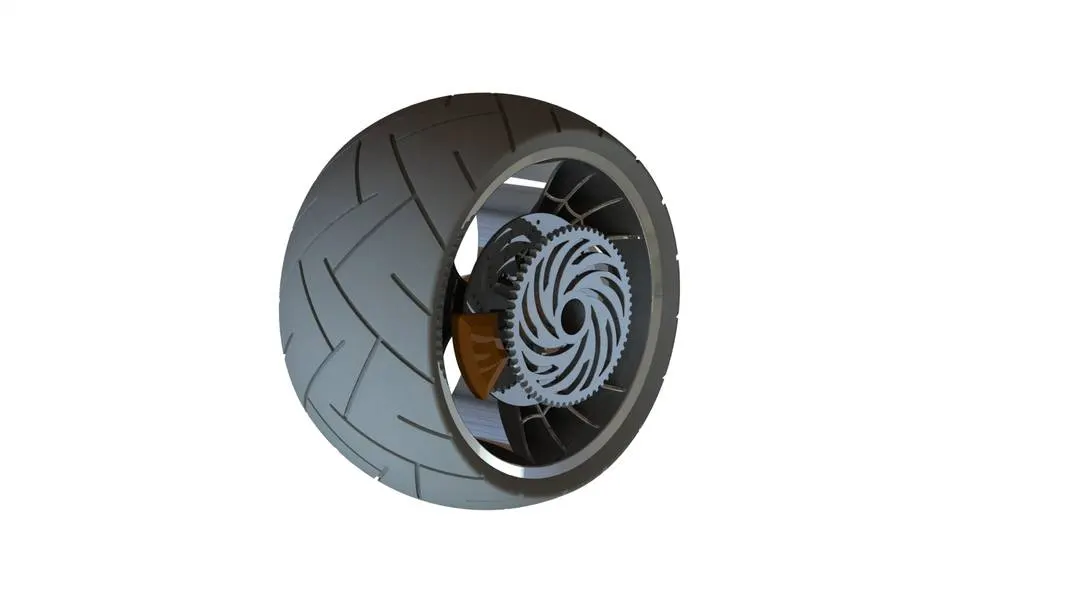
The front wheel in our chopper design has four parts rim,rotor,tyre and calliper. At he begining the sketch profile for the rim is drawn on the front plane, We use revolve feature by selecting the sketch and axis for rotation, this will give us a rough 3d overlay for rim. A disc for brake is created using circles and extruding it. A hole is made in the front hub for the fork assembly using cut extrude. Using splines we can give some design to the rim, we will create one half of the spider web design and mirror across a construction line. For callipers we select the face of the disc as sketch plane and extrude it, Tyre is designed using revolve, the grip on the tyre is done by sketching on the front plane and applying cut extrude feature, we will add appearance to the parts .
Rare wheel:
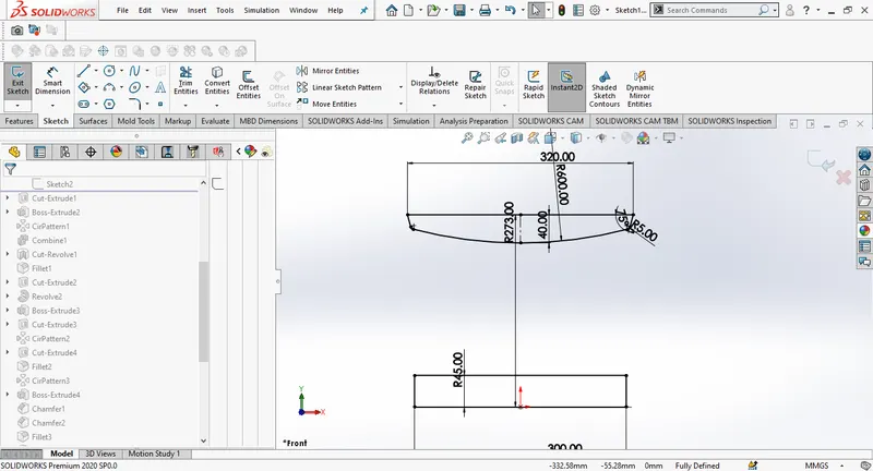
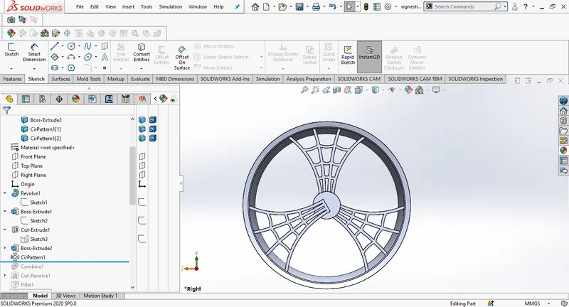
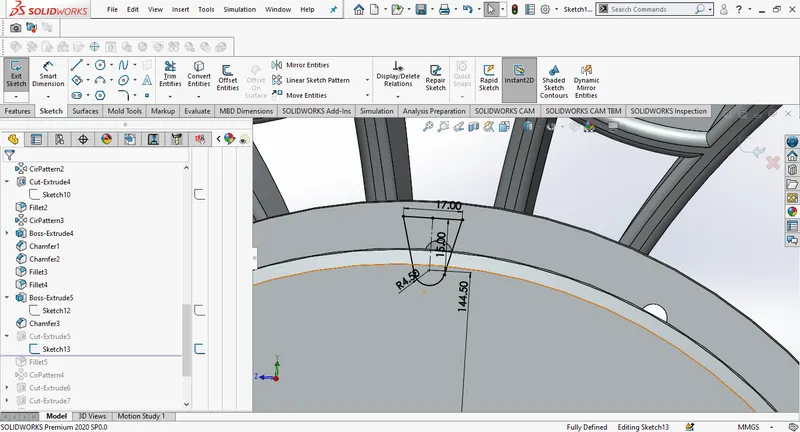
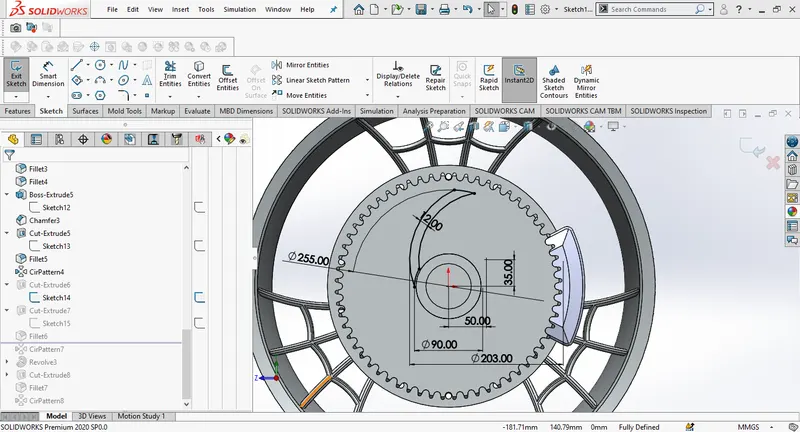
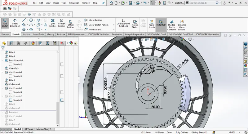
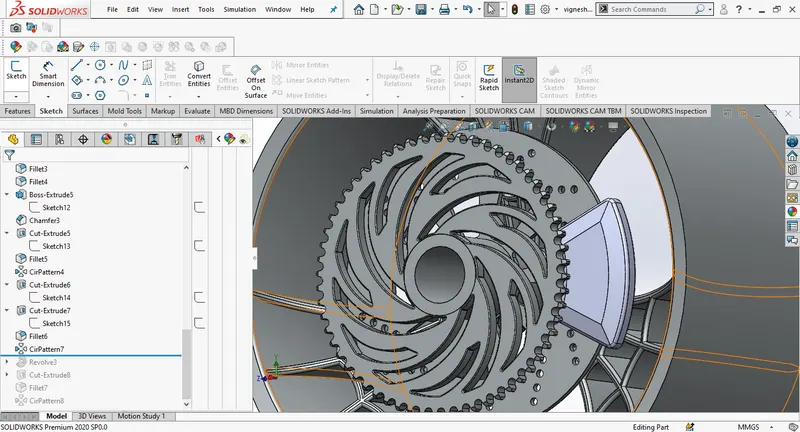
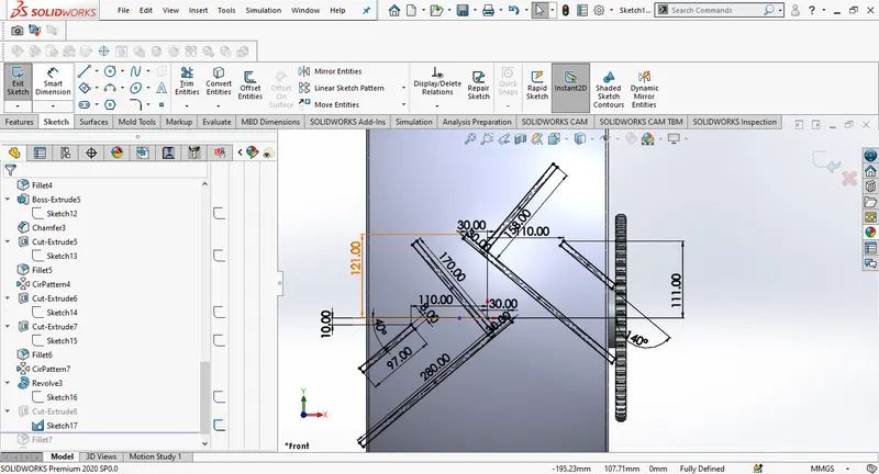
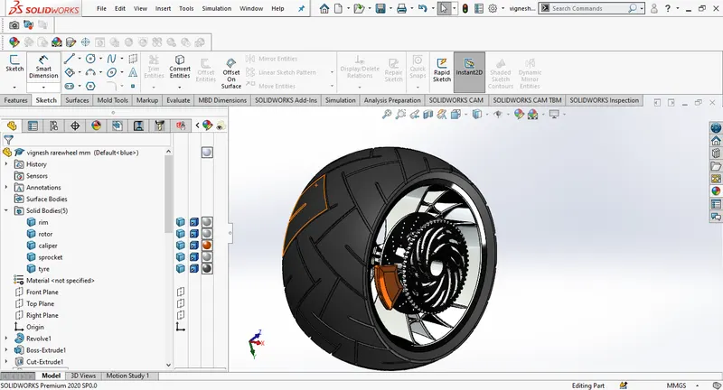
The design process for the rare wheel is mostly similar to the front wheel, axel and chain sproket are included to the rare wheel design, We design the axel by using sketch with some lines and revolve it arround the axis.sproket is connected to the edge of the axel and it is designed by using features like ectrude, cut extrude and circular pattern for tooth on the sproket, The design process is same for grip except the sketch pattern.
Front fork:
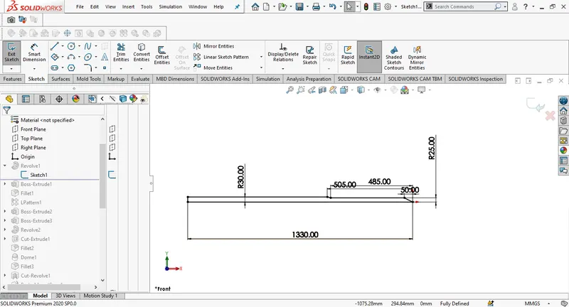
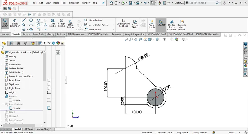
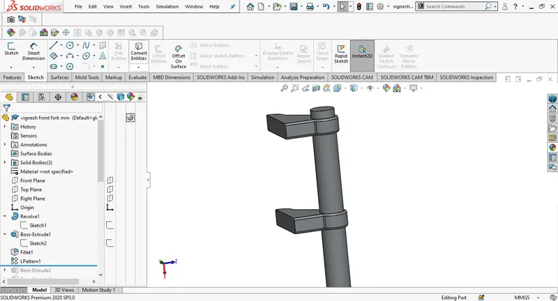
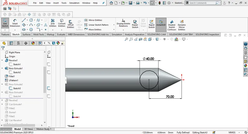
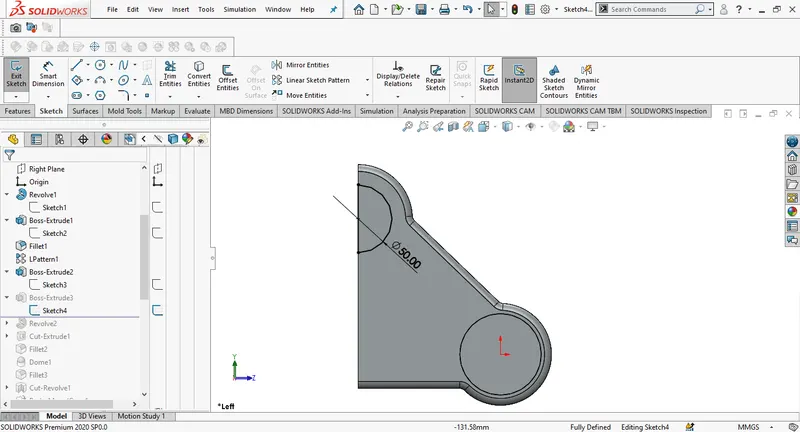
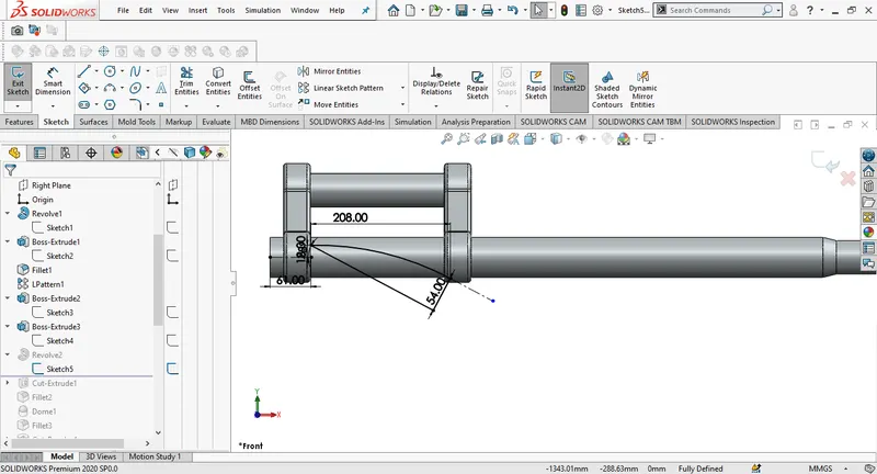
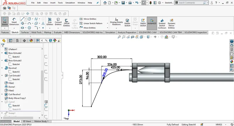
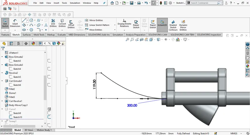
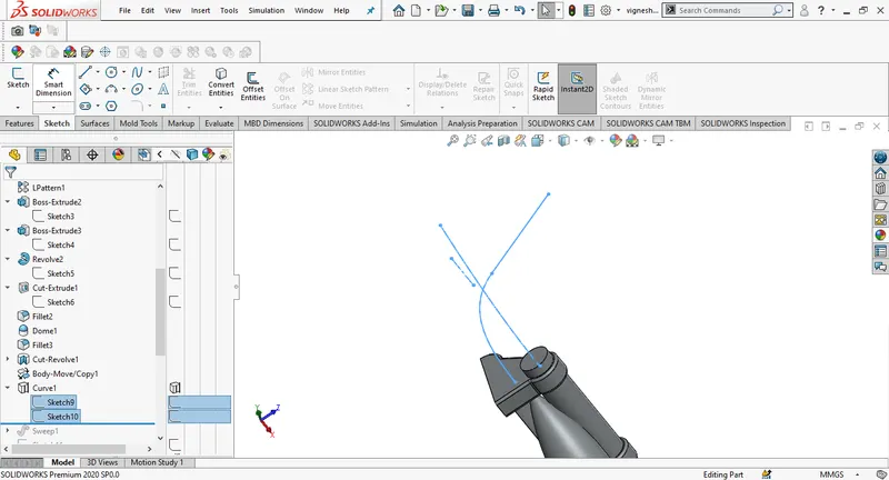
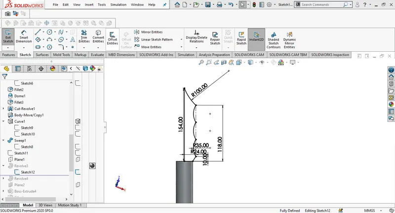
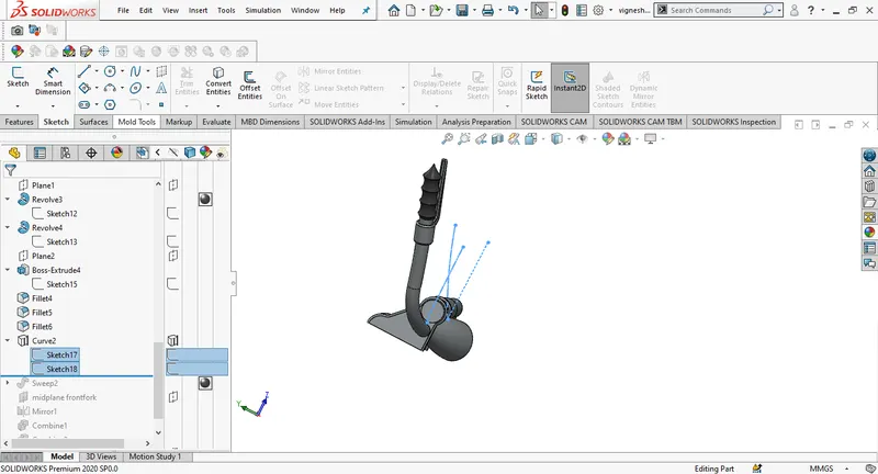
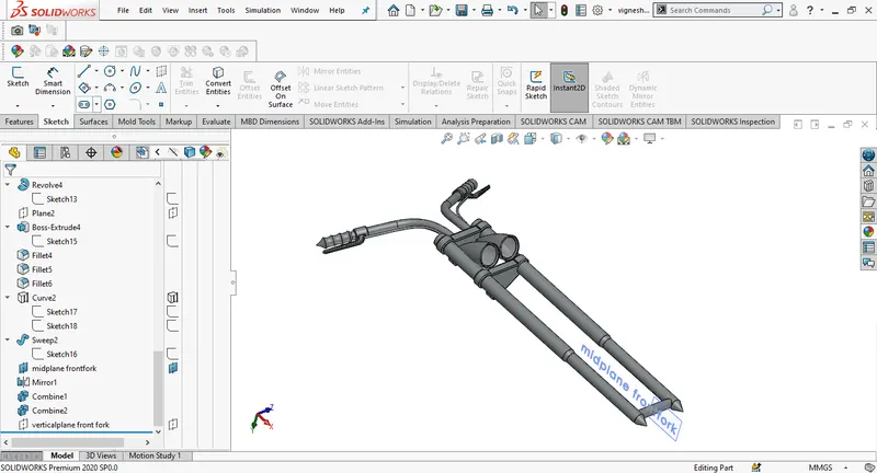
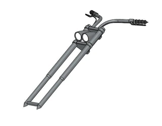
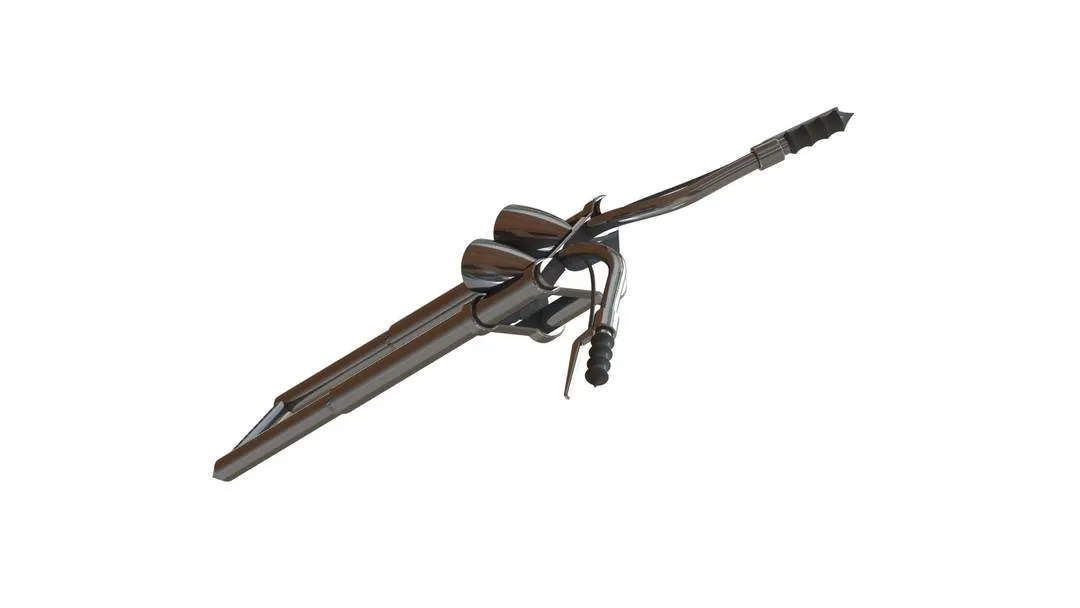
The front fork of our chopper holds the front wheel, it has two columns with shock absorbers which are held by the help of triple clamp. We will try to make one half of the front fender and just mirror entities to complete the part. Draw a sketch on front plane for one column and use revolve to finish the column, then a sketch is drawn for the triple clamp using proper dimensioning, draw a sketch for one of the lamps on the same plane and use revolve to finish lights, Using cut revolve on the projecting surface of lamp we can achieve the dome like surface which makes our lights look more real. The handle is created by sketching some splines with proper dimensions. For the break wires we use projected curves to get a 3D curve. The sketch for the wires is done in two different planes and then they are projected. By using sweep and selecting the curve we can create break wires. Select the entire half of the fork and mirror them across midplane, merge the components together to combine entire part. We will finish the front fork by adding some appearances.
Chassis:
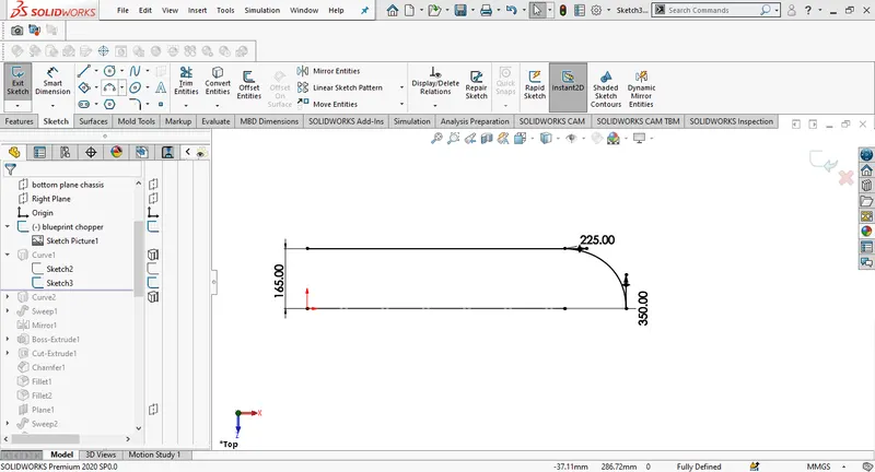
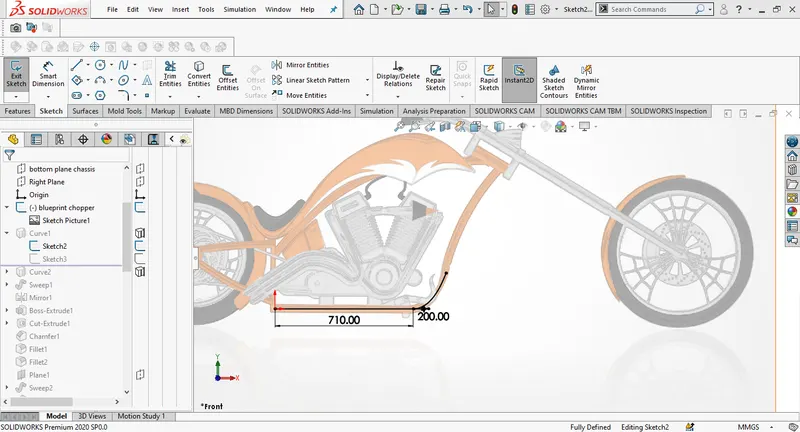
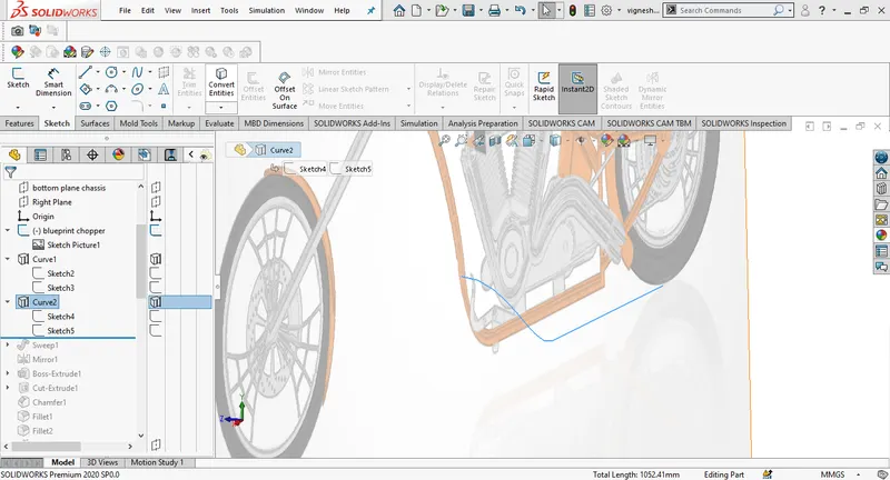
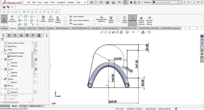
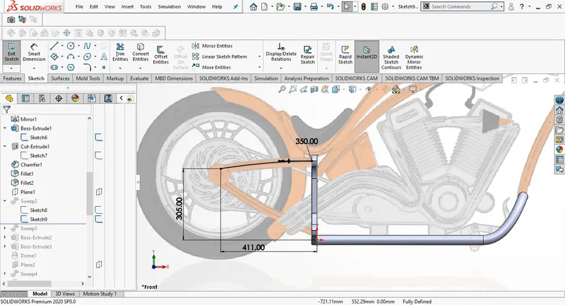
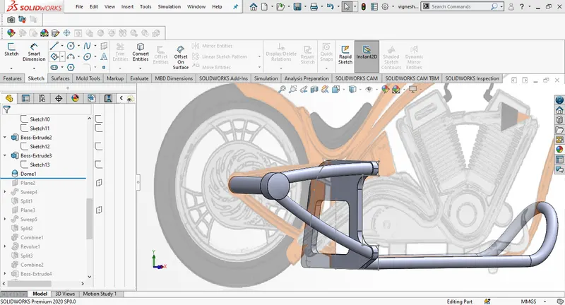
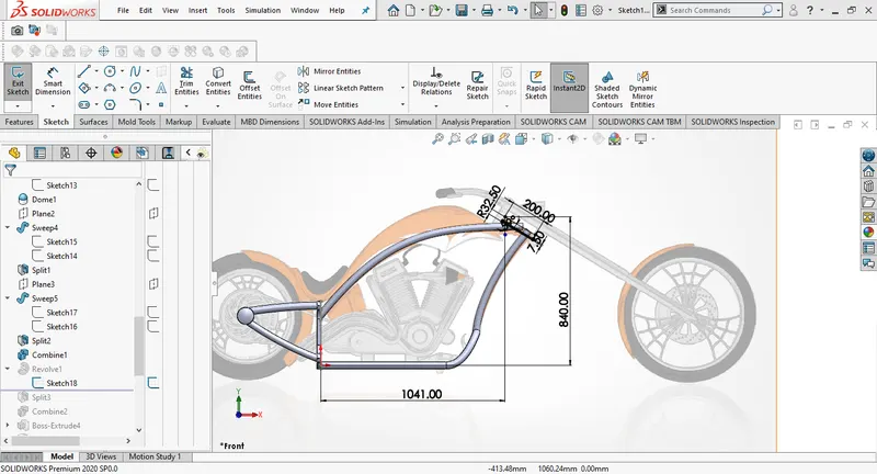
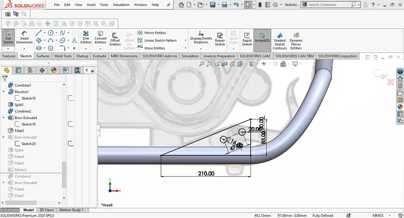
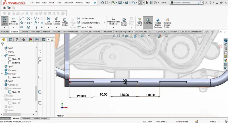
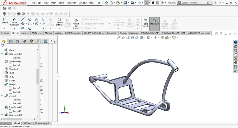
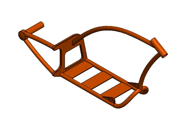
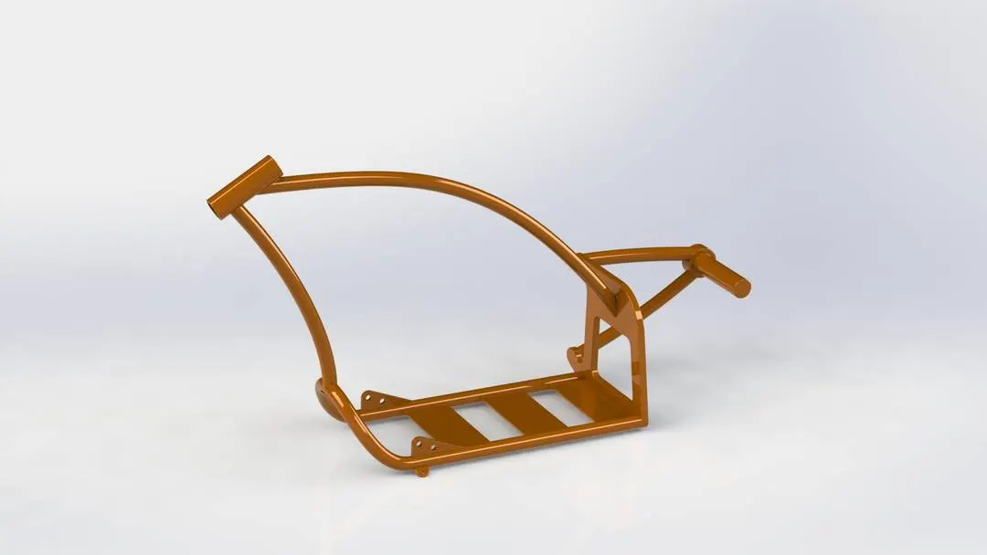
In the design process of the chassis we take the help of sketch picture which we can import from tools. We will get an overlay of the sketch from the sketch picture , we can simply call it as blueprint. The curves in the chassis are generated using splines and projected curves. The rear wheel hub is created by using splines and few features like extrude, sweep, dome and fillets.
Engine:
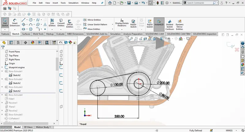
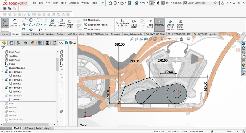
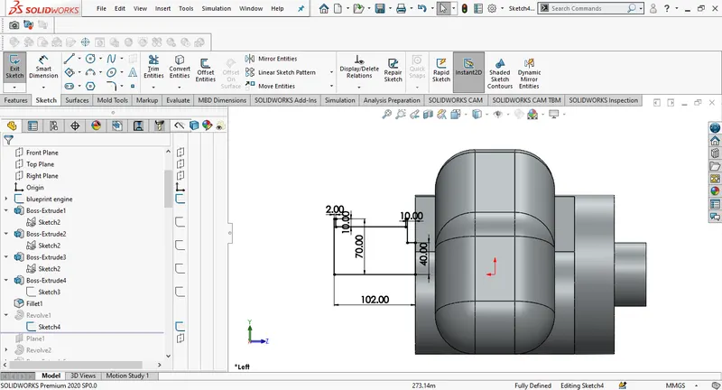
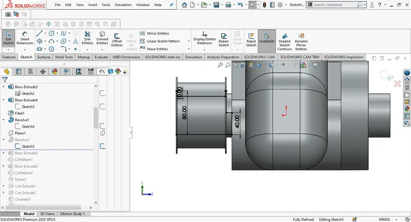
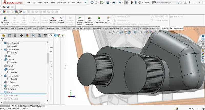
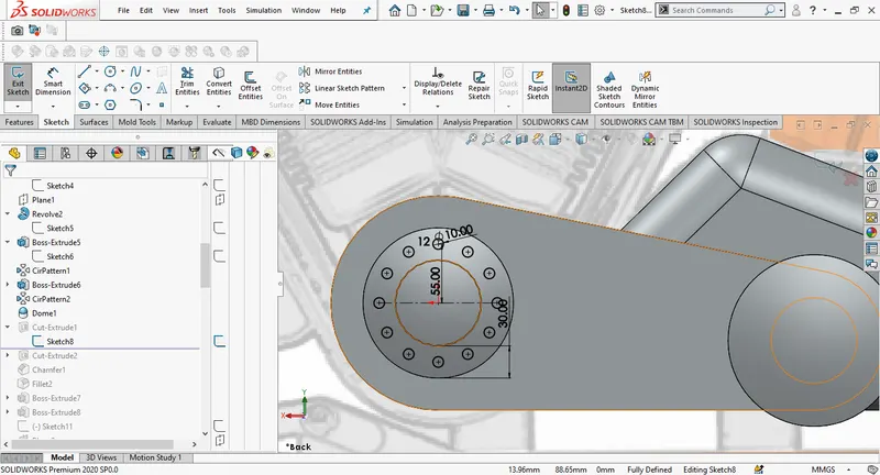
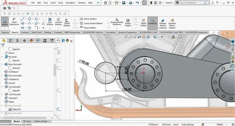
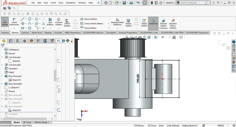
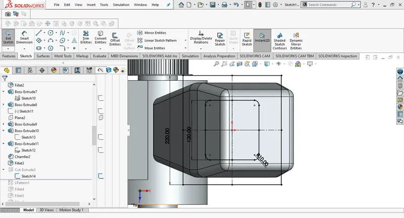
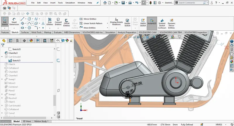
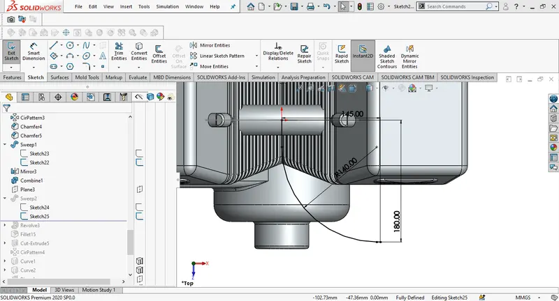
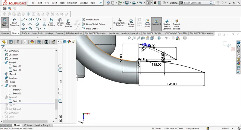
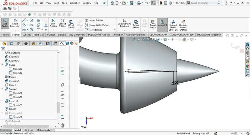
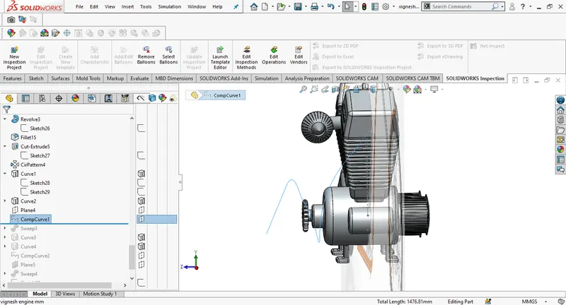
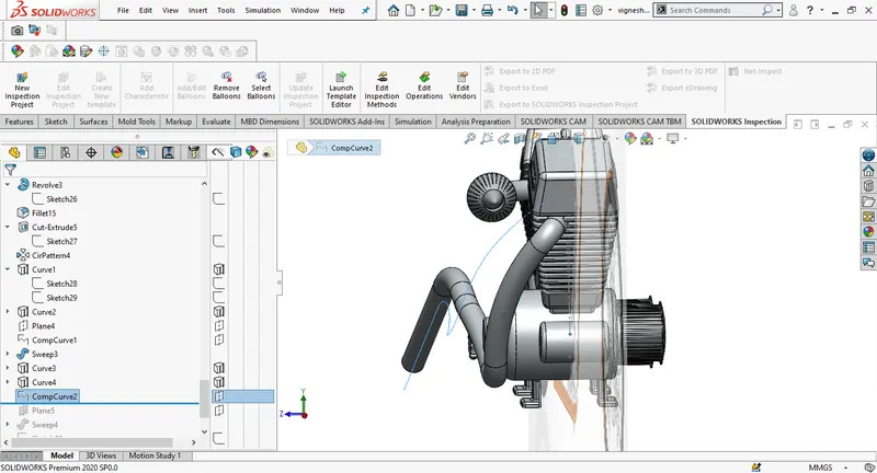
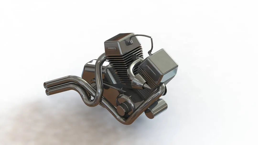
Engine is the most important part in any automobile, We take the help of sketch picture to design of engine, Using different sketching tools we can get the overall outlay of the engine then we will well define the sketch to use features and create the engine base. We can design the cylinders and fins by using boss extrude and linear pattern, here we design one cylinder and mirror it for another. The sketch for the air filter is created using splines and dimensioning them. The pattern on the filter is done by sketching, extrude cut and circular pattern, finally fillets are applied to necessary faces.
Gas tank:
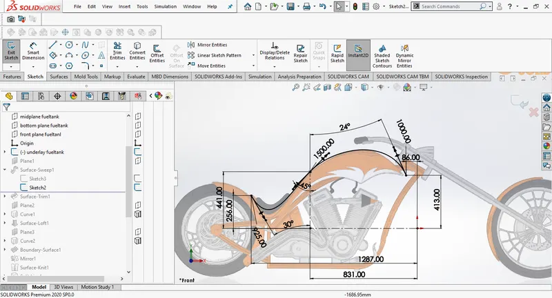
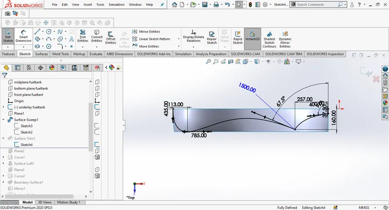
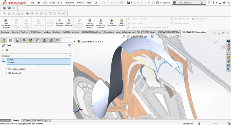
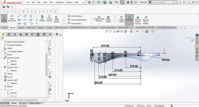
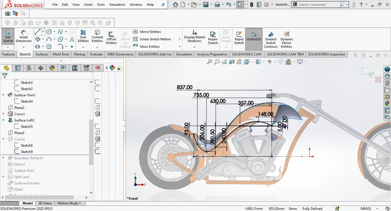
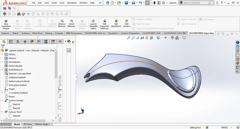
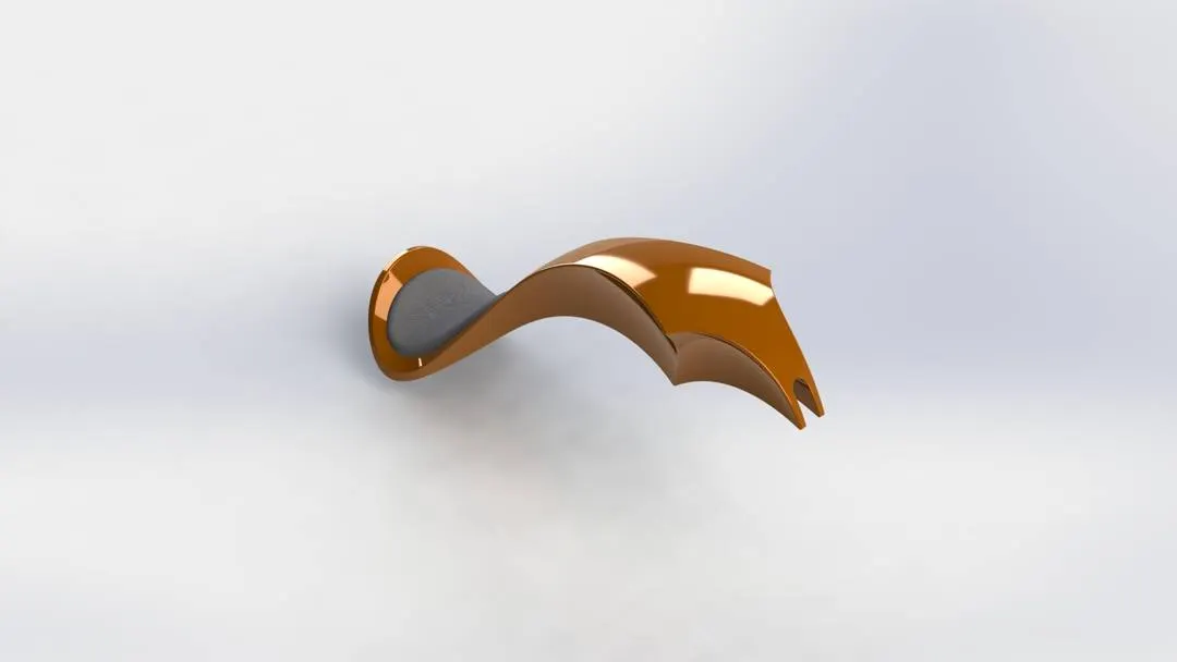
We can simply use our sketch pitcher for reference to create fuel tank ,Fuel tank can be designed by using these features swept surface,loft surface,boundary surface,projected curves, knit surfaces,sweep cut ,shell,mirror entities. We will project the curve by using two sketches one in the front plane and the other in the top plane, using splines. Using swept surface and boundary surface we create one half of the tank. Using another sketch extrude with appropriate dimensions we can make seat for the chopper. Mirror the half tank and knit surfaces together. Add appearences at the end.

Assembly of the chopper:
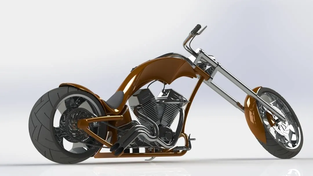
All the parts created are opened inside the assembly window one by one and are fixed in the assembly using the required mates. Chassis is the base of our chopper design so ww will fix the chassis first inside of the assembly, engine is mounted to the chassis using coincident mates with the front plane in the assembly and the chassis, pedals are assembled with concentric and coincident mates, concentric and angle mates are used to assemble kickstand, transmission belt is fixed to engine using concentric mate. Oil tank is mounted on the engine base with coincident mates. Rare wheel is assembled to chassis using coincidend and contric mates, both the front wheel and rarewheel are fixed on top plane using tang mates. Rare fender is fixed to chassis with parllel, coincident and concentric mates.Distance and coincident mates are used to fic fuel tank to the chassis. We assign concentric , width, limit angle mates for fixing front fork in our assembly. Front fender and chain are fixed by concentric mates. If we float the chassis and move it every part should move along with chassis.
Photoview 360:
Its a solidworks add in that produces photo realistic renders for solidwork models, It's a highly interactive environment for viewing your designs as well as for creating photorealistic renderings that you can use to showcase your designs. We cn add decals, appearences , setting camers, edit scens to acheive photo realistic renders.
Solidworks visualize:
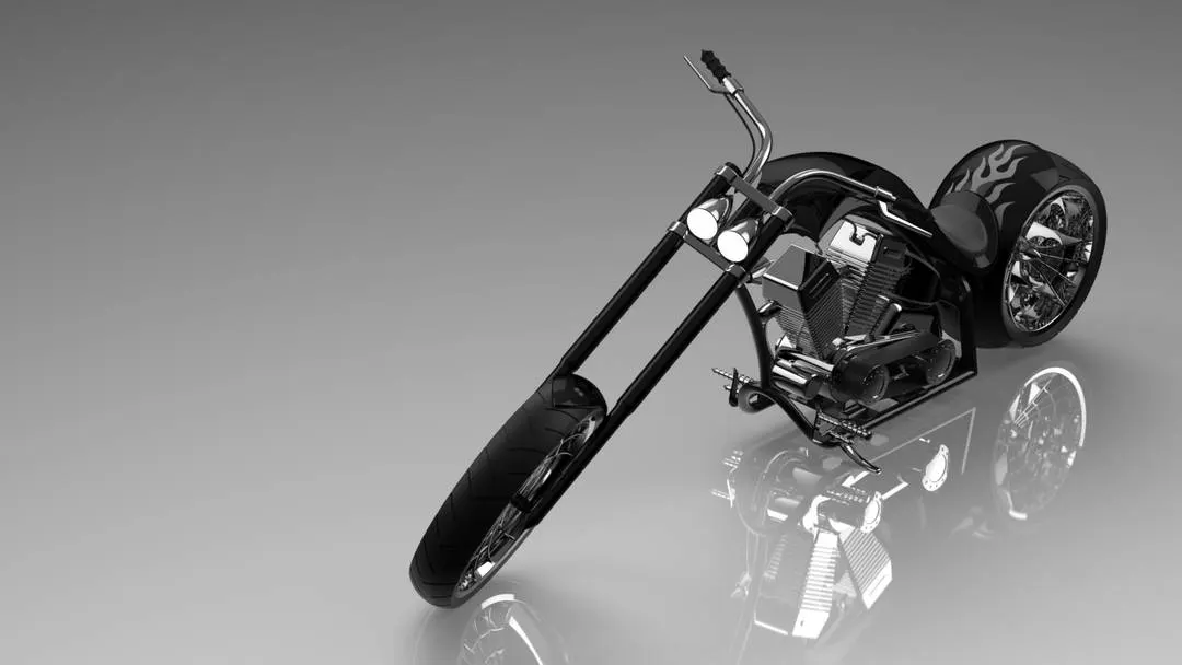
SOLIDWORKS Visualize helps to get photo-quality imagery, interactive animations,Visualize to help you create the most beautiful content possible, We can edit the appearences, envoirnment add lights, decals, set scene and give a real view experience of CAD files.
Conclusion:
Understanding and learning about the part modelling in solidworks.
Assembling of the part models, adding decals , editing envoirnment and photo rendering using photoview 360
creating a realistic render images for CAD files using SOLIDWORKS Visualize.