Radar Mast & Final Assembly of Yacht
DESIGN & ASSEMBLY OF YATCH
Objective: The main objective is to create a yatch model inside solidworks by breaking down the design into parts and assemble them using solidworks assembly.
Introduction: This is the detailed report of designing yatch from modelling it parts to the rendering in solidworks visualize. Most of the design process is about the surface modelling so most of the desing preocess is about the use of various surface modelling tools.
DESIGN METHODOLOGY:
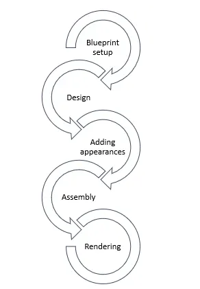
Start with setting up the blueprint. Parts in the entire model are designed induvidually (Propeller, radar, garage door, hull, seats, superstructure.) adding suitable apprances at the end of each part design.Assemble them opening assembly file. Finally renders are created on solidworks vizualize.
DISCRIPTION:
Blueprint setup
1.Set the blueprints first by opening new part file. Select the front plane in the feature tree and draw a 2D sketch.
2.Go to tools , then insert sketch picture, select the blueprint front view, adjust to the required dimensions and exit.
3.Change the name of sketch to blueprint_front view.
4.Create new sketch on rignt plane, insert sketch picture for blueprint_side view.
5.Select top plane and insert new sketch picture for blueprint_bottom view.(change the name of top plane to bottom plane)
6.Create a new plane in reference to the front plane with a distance dimension of 32920mm.The new plane is back plane and blueprint for bPack view is fixed in this plane.
7.Create a new plane in reference to the bottom plane 10000mm above to the refrence plane, select 2D sketch and insert blueprint of the top of yatch and rename the sketch to bluprint_top view
8.All the blue prints are fixed and this helps throught the design process
PROPELLER:
Open new solidworks part file and save the file as propeller.
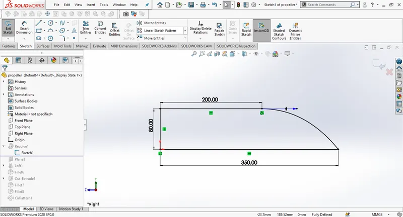
Here is how to create the hub of the propeller. Draw a new sketch selecting right plane as per the design , with specific dimensions. and use revolve to design propeller hub
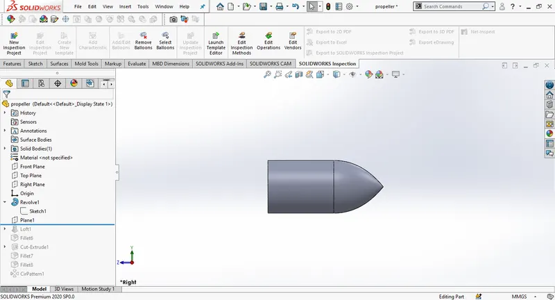
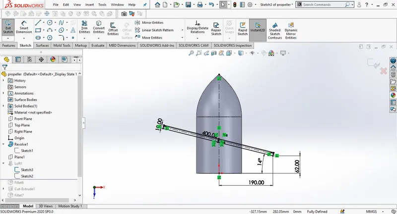
Create a new plane in reference with the top plane. draw a three point rectangle on the bottom plane as here in the picture, draw again a three pont rectange on the new plane and now suing both the sketches create soild loft.
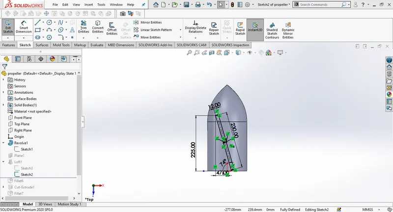
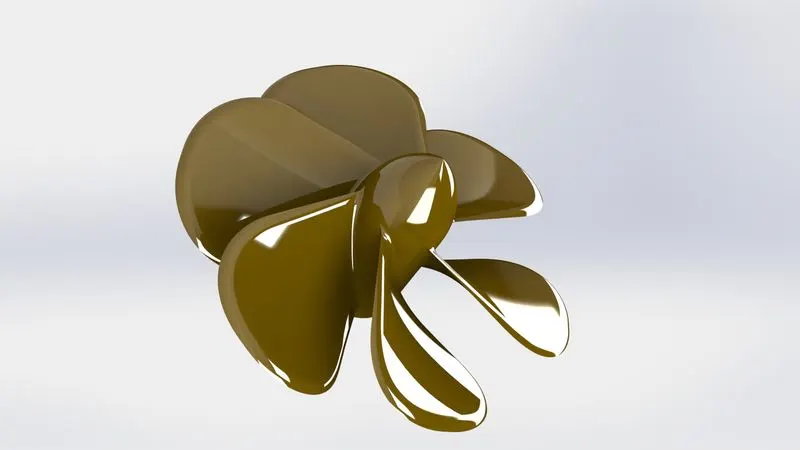
Add fillets to the blades. using cut extrude create a hole to fix the shaft. create a circular pattern by selecting any circular edge and the features need to be patterned.Add final appearance
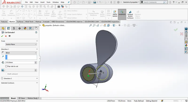
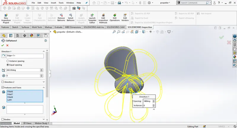
RADAR:
to design radar select right plane and 2D sketch and draw four lines with required dimensions then exit to extrude the sketch to 700mm distance from sketch plane, give the required fillets
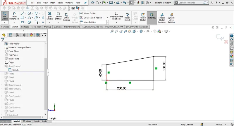
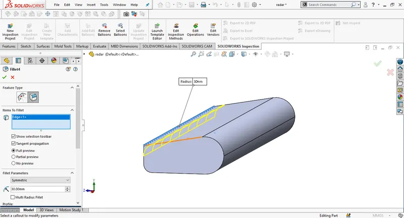
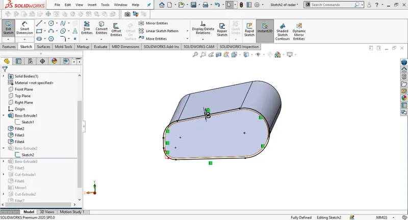
Select the right side of the the extruded surface to make a new sketch offsetting the edges to 3mm outwards and extrude the sketch to 10mm.
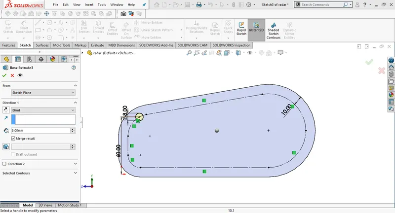
Draw a new sketch in the same way offsetting the edges to 10 mm inwards. Convert the sketch into construction geomentry, draw a circle on the construction geomentry with required dimensions and extrude the sketch to 3mm by enabling merge results.Add fillet to the extruded part.
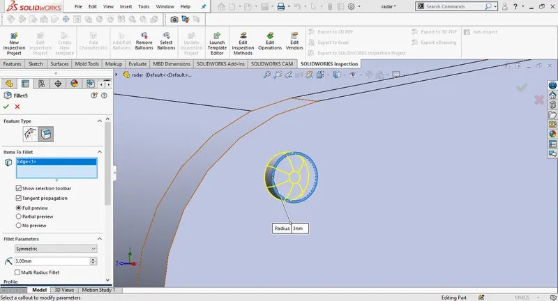
Draw a polygon of width 3.5mm on the fillet surface and then extrude-cut to 1.5mm.
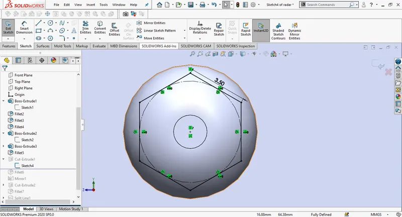
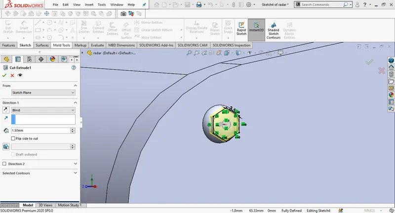
Draw four points with required dimensions and make a sketch driven pattern by sellecting the features to pattern.
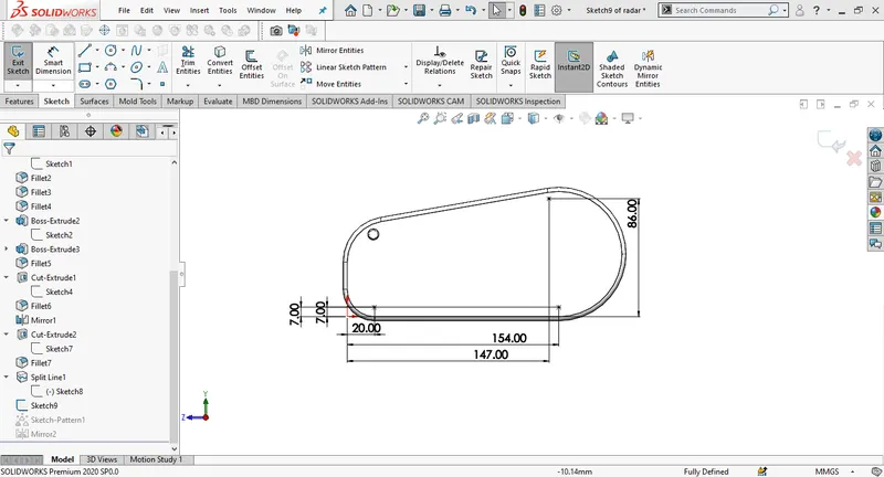
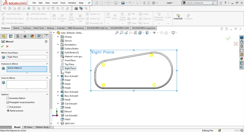
Add the fillets at the required areas before inserting mirror. Select the right plane as the mirror face and select the entities that are need to be mirrored.
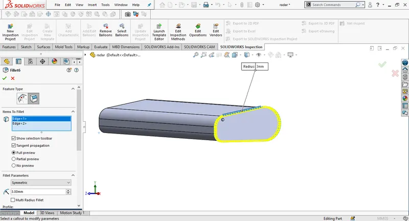
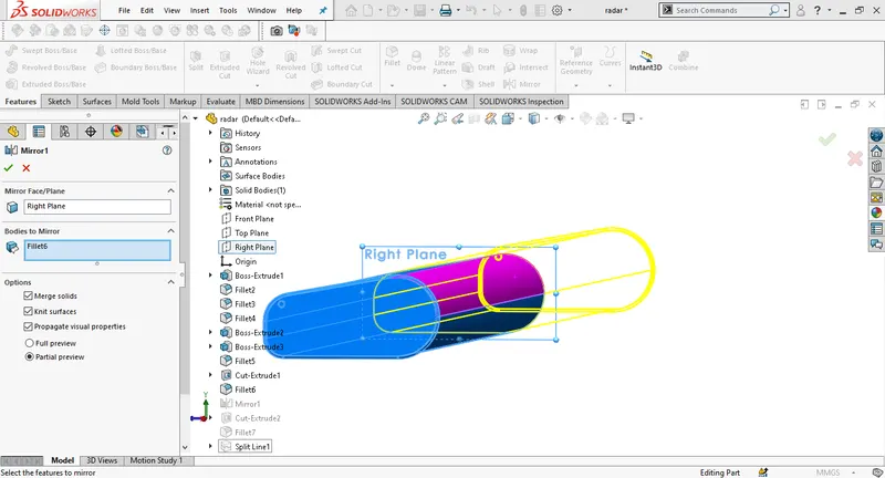
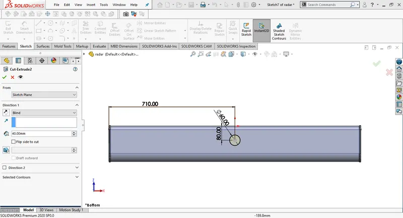
Create a new sketch on the bottom surface of the radar for making a mounting. Draw a circle and create an extrude cut (40mm Depth). Give the fillets to the circular edges.
Draw a centerline on onw side of the radar surface go to sketch entities and select add text. using centerline as reference curve add text, you can also change the font as per the need.
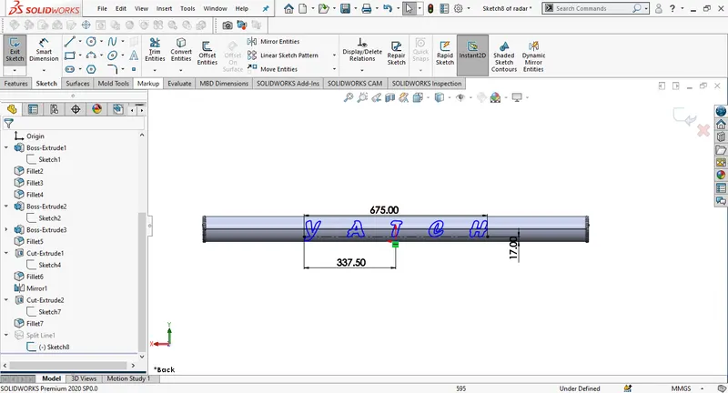
add the appearences.
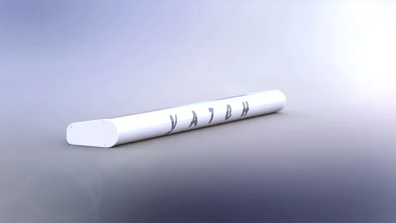
HULL:
Hull is the biggnest part in the entire design. To design hull make use of blueprints. We will model the surfaces and then create into solid after trimming them. Open the blueprint setup start with saving the file as hull, go to the bottom plane and draw a 2D sketch using blueprint. Draw an another sketch mid plane. Project both the sketches for the curve.
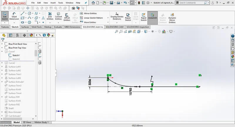
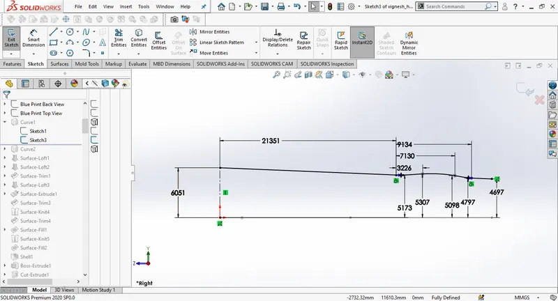
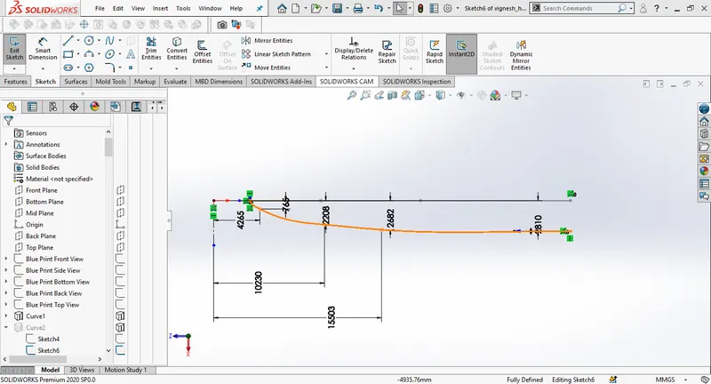
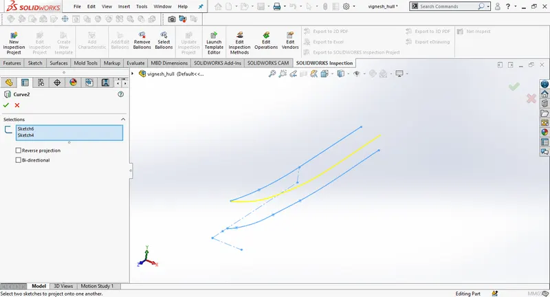
Drawa a sketch connetcting both the curves.
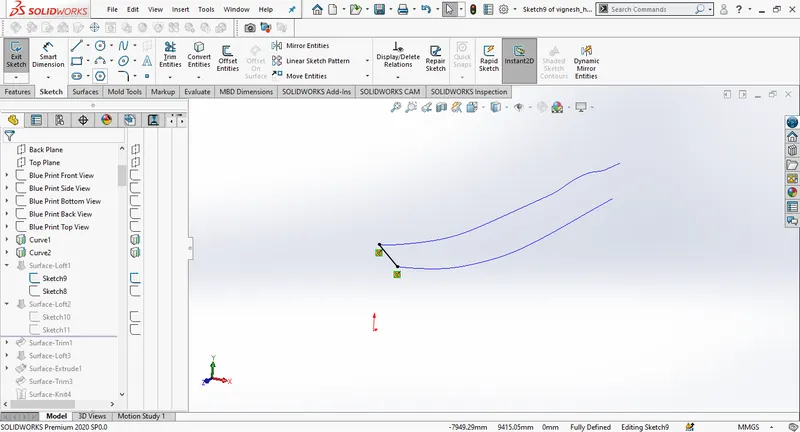
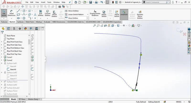
Insert surface loft seloecting curves 1&2.
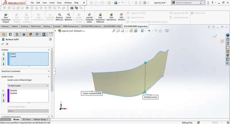
Create a new sketch on the midplane.
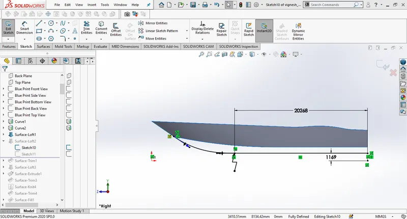
Draw a spline on the back plane drage and adjust the spline close to the blueprint and define the sketch using coincident relation. Then create surface loft
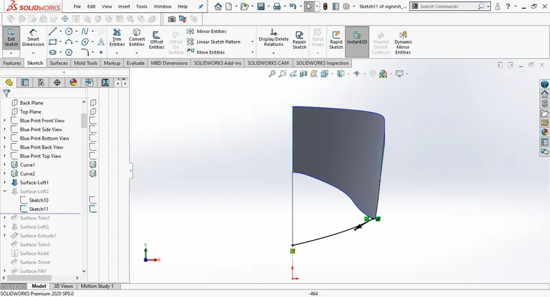
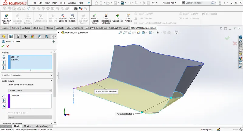
Draw a 2D sketch on the midplane add dimensions , trim the rear part using split. Dreaw a spline as in the picture. Then create a surface loft.
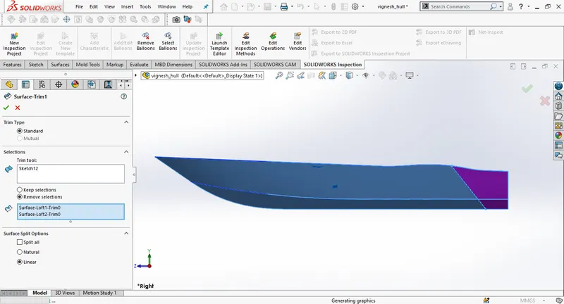
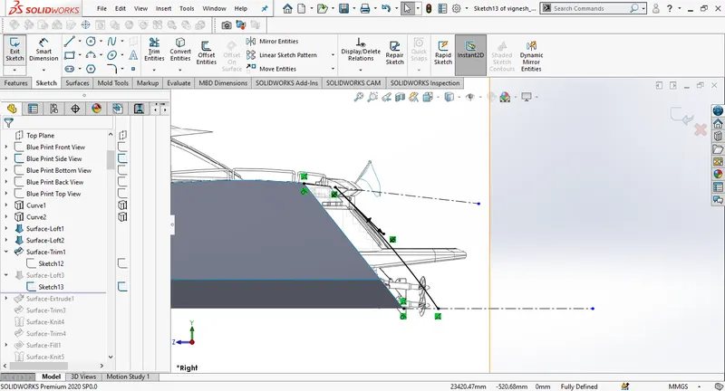
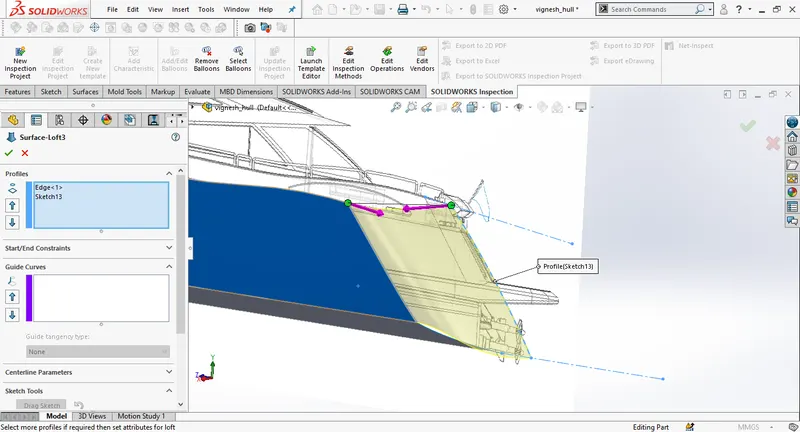
Create a new sketch on the mid plane and extrude surface to 5000mm and trim the rear part of both the surface lofts using trim surfaces.
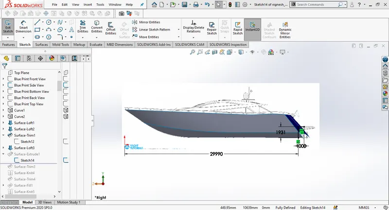
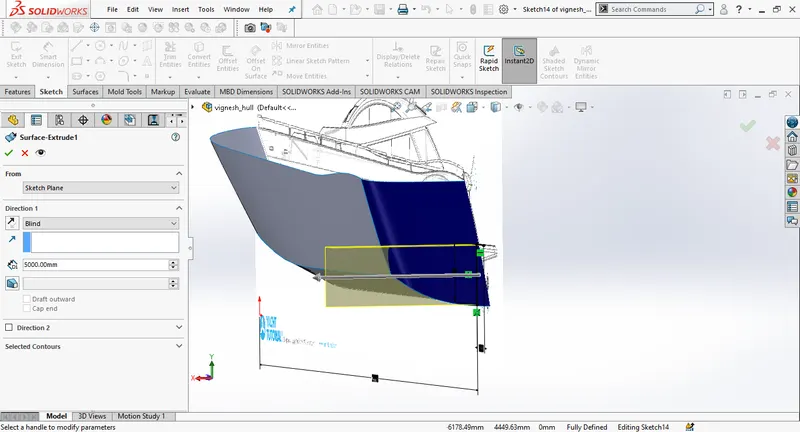
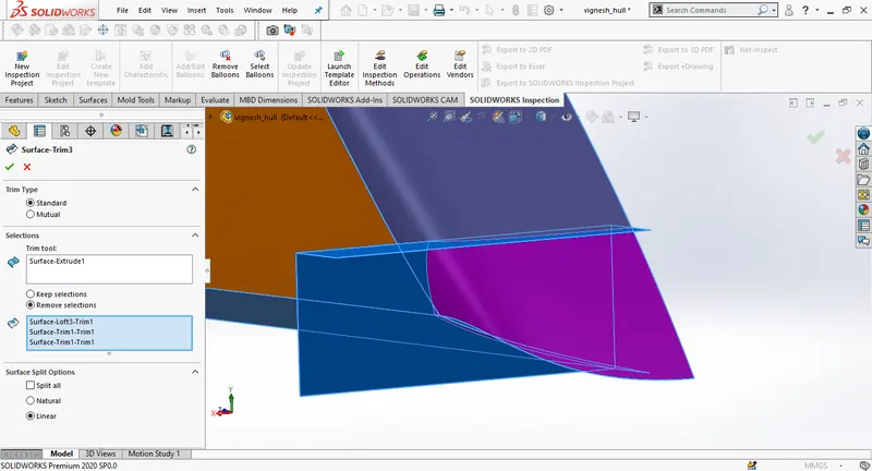
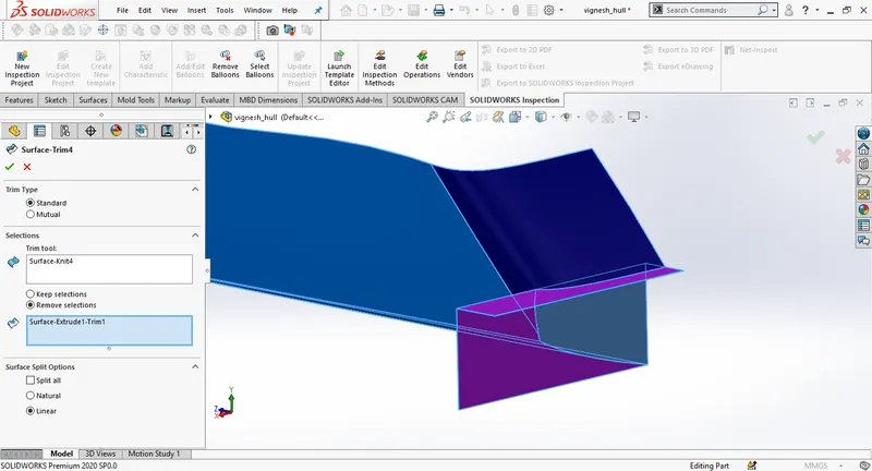
Draw a new sketch on the mid plane by connecting the end points of lofted surfaces, then creat a surface fill for top of the hull. Create another surface fill for open side , Knit all the surfaces together before creating the surface fill, correct or adjust the design if there are any blue lines. create a shell (120mm)
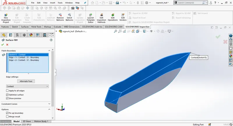
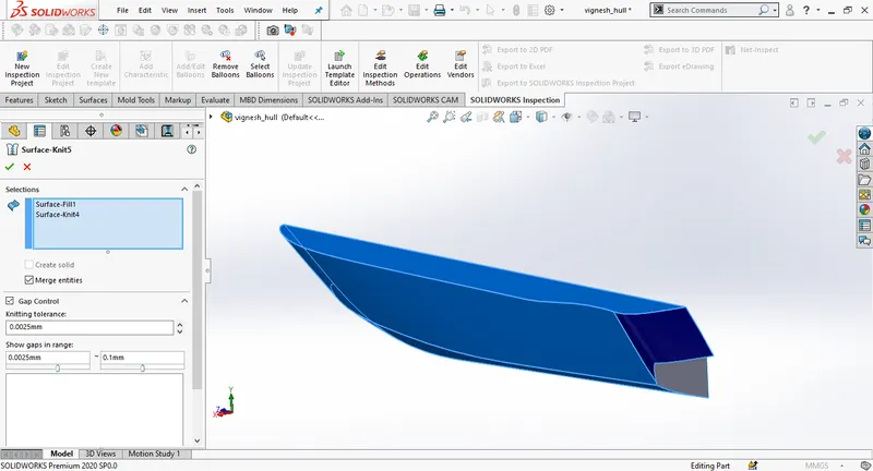
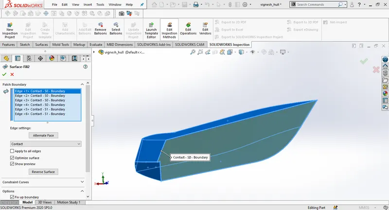
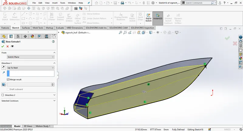
Create a new sketch on the midplane and extrude the sketch.
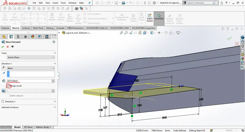
Create a new sketch on the mid plane and give the dimensions and extrude it to 3070mm, create an extrude cut by drawing a new sketch on the bottom plane.Give the fillets at the required areas.
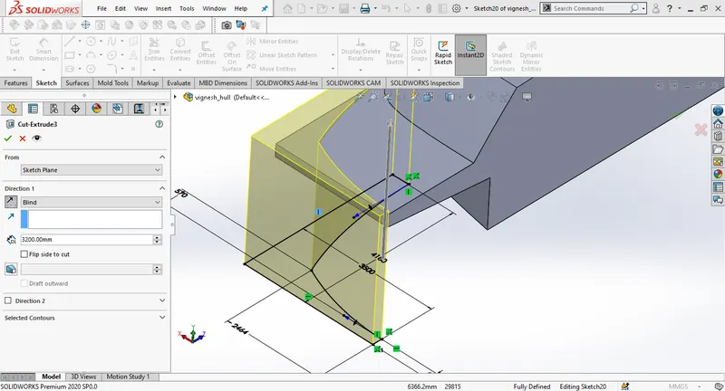
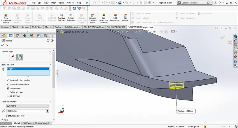
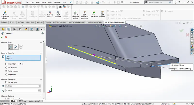
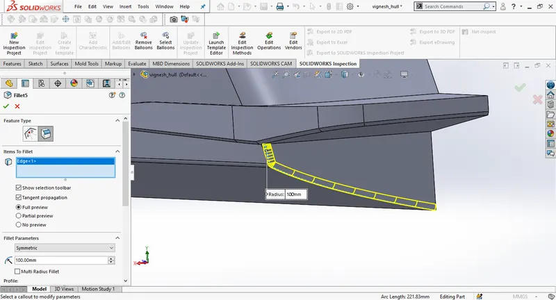
Create a new plane using first plane as referance, and offset it to the distance of 5000mm. Draw a new sketch on the new plane. Go to cutextrude , enable offset from surface, select the side surface of the hull snd add fillets to the corners.
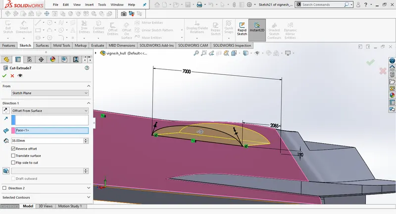
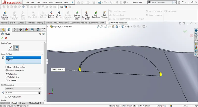
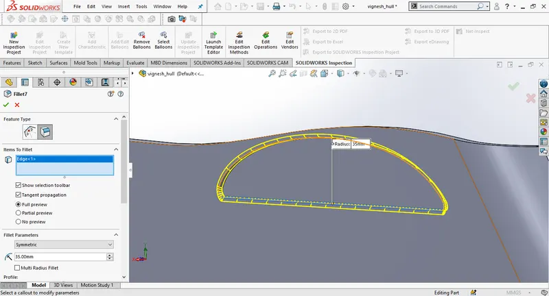
Go to the Plane 1 and draw a 2D sketch, Use blueprint sideview and draw lines for windows matching close to blueprint. Use cut extrude using direction off set from surface. Fillet the edges of the windows.
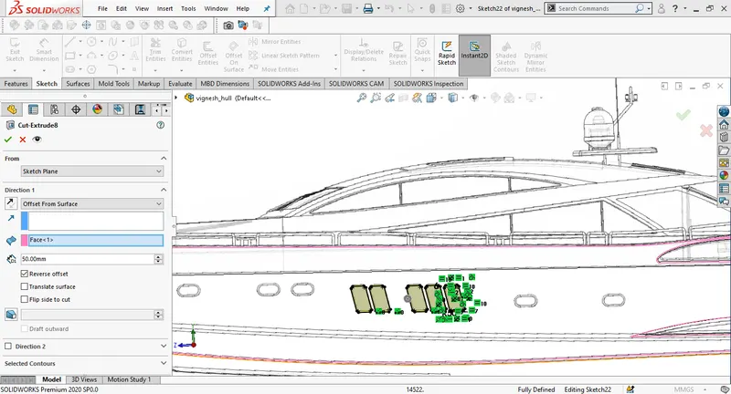
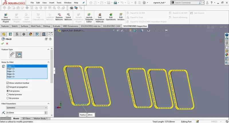
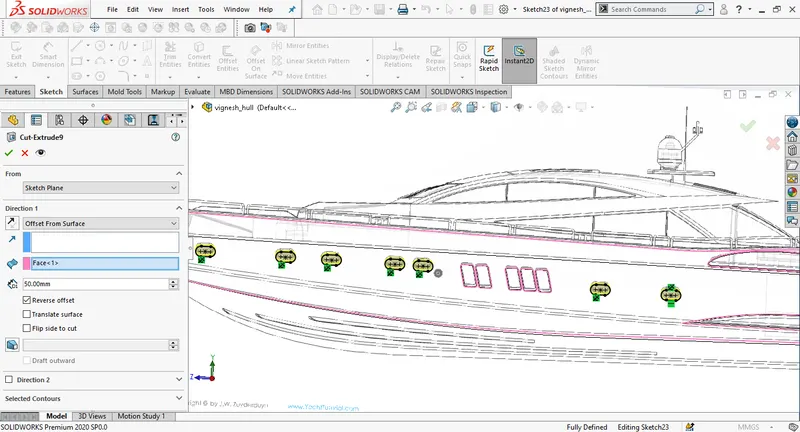
Use slot to draw portholes close to the blueprint and fix the slots manually using fix. Create an extrude cut , change the direction to offset from the surface enable translate surface.
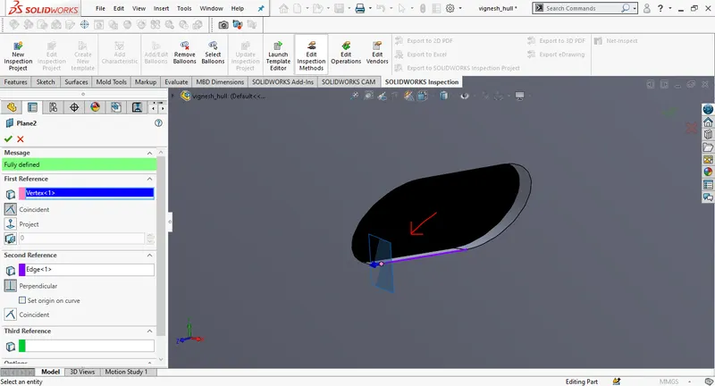
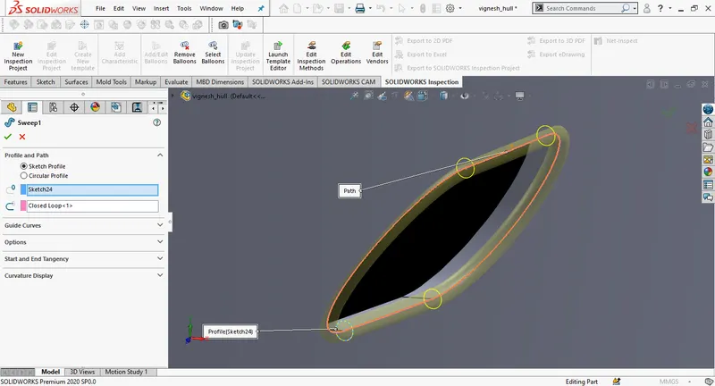
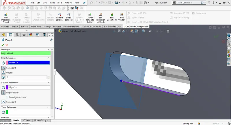
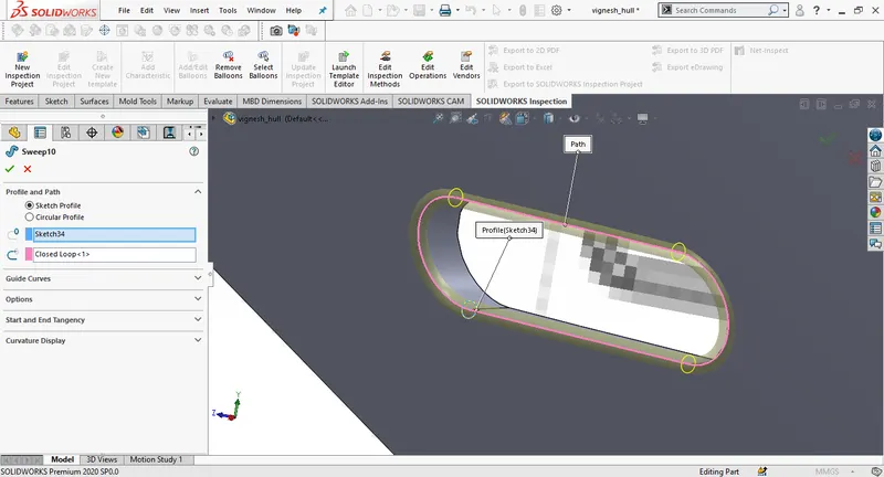
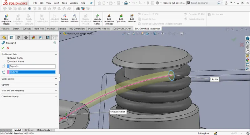
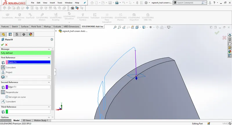
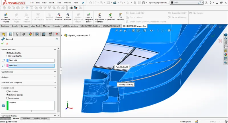
Create a new plane, select the point on the parthole as first referance and the edge of the parthole as second referance, Draw a circle of radius 40mm at the origin of the new plane. Draw a 3D sketch uisng convert entities for the outer edge of the porthole. Then create a solid sweep selecting 2D sketch as profile and 3D sketch as path , repeat the same procedure for all the portholes.
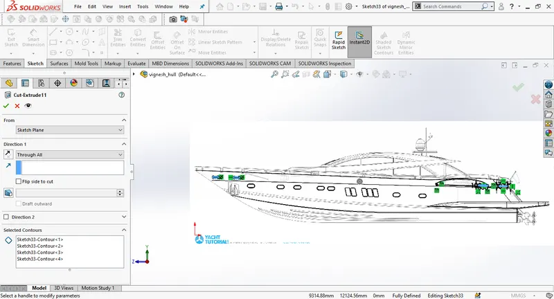
Create an extrude cut by drawing a new sketch on top plane using blueprint top view, use cunvert entities and trim the extra edges to close the sketch.
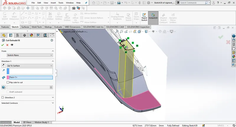
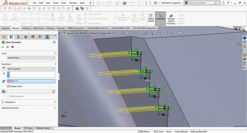
Draw a new sketch suing splines match exactly with the blueprint, offset the sketch to120mm, close thw skrtch using two lines and use extrude boss, change dimensions to 10mm
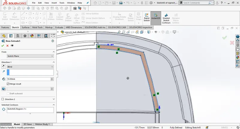
Draw a new sketch using convert entities draw vertical line 60mm away from edge, trim the extra lines, use extrude boss and give distance 10 mm
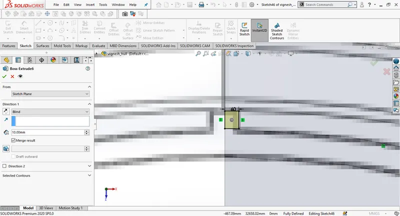
Draw a new 2D sketch on the top surface of the hull, using straight lines and extrude the sketch to 10 mm

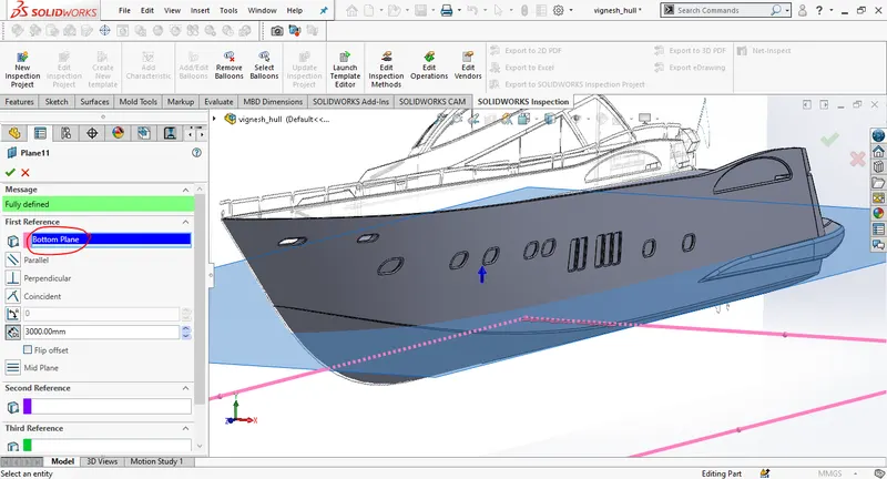
Create a new plane using bottom plane as first referance and give the offset distance of 3000mm facing upwards, create a new 2D sketch on the new plane, unhide the blueprint bottom view draw a sketch with splines and straight lines. Extrude the sketch to 75mm offsetting from the surface.
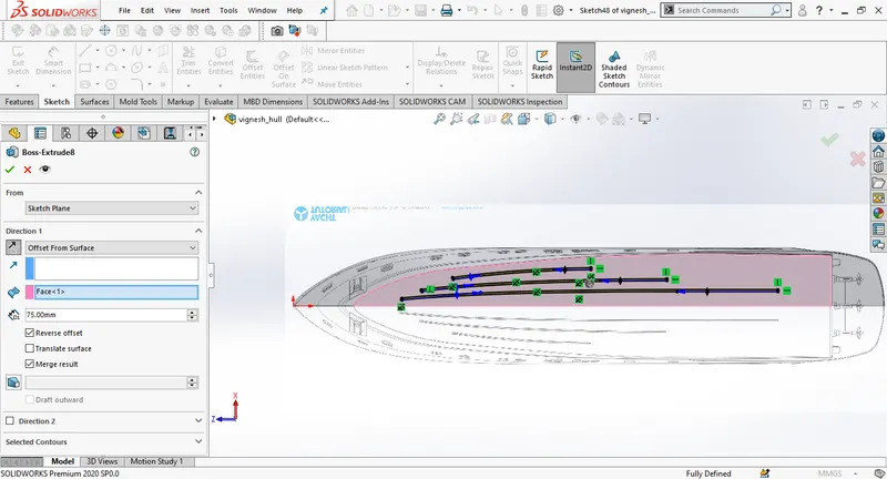
Draw a new sketch on the top surface of the hull. and follow the steps to design anchor lever.
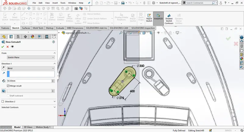
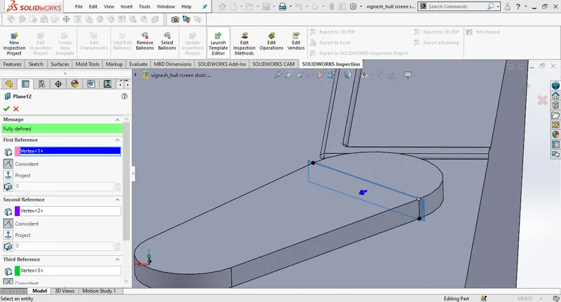
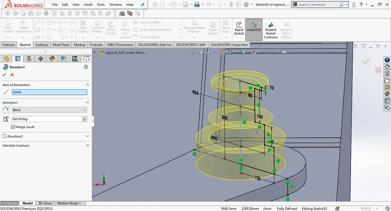
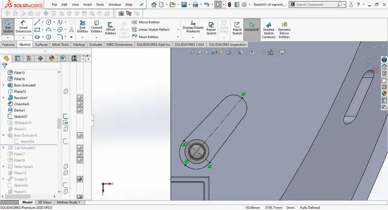
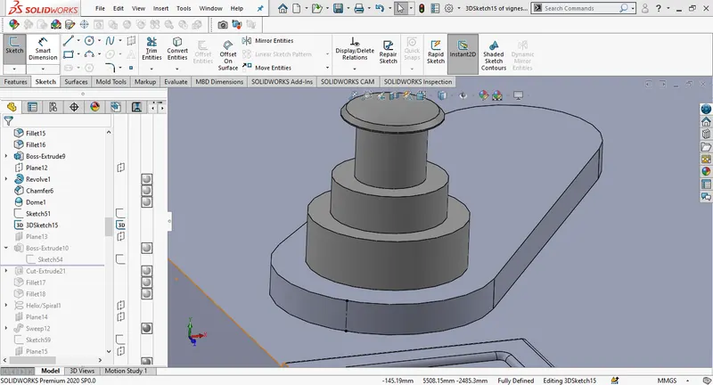
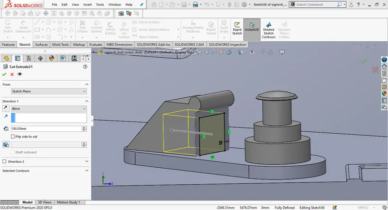
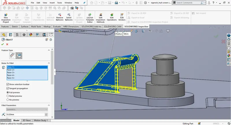
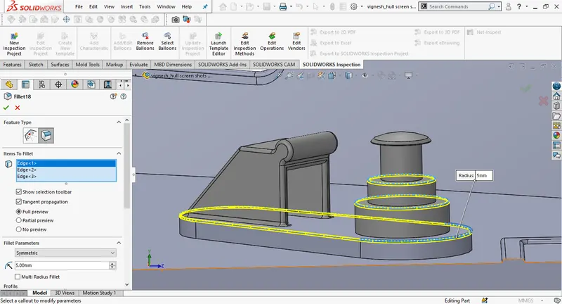
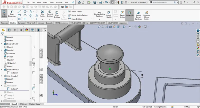
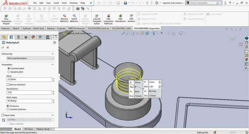
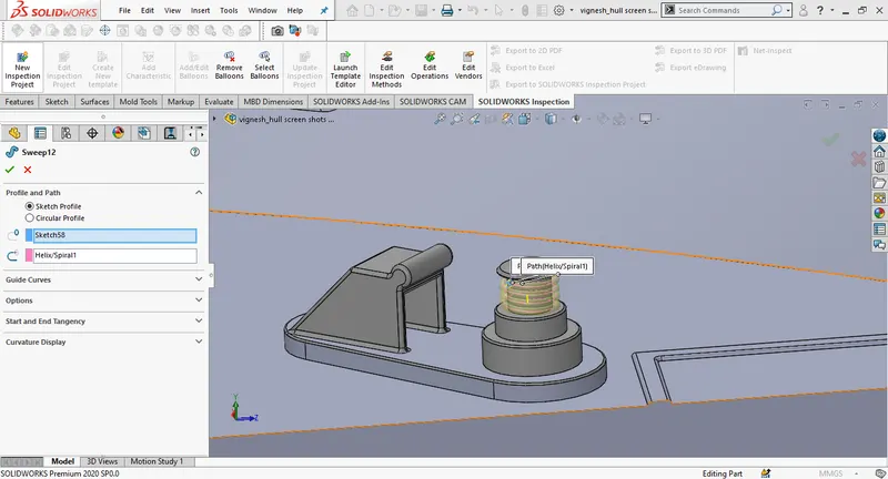
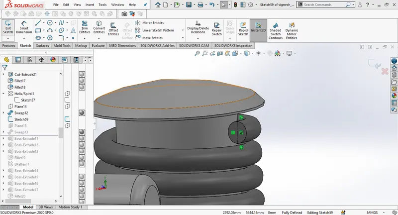
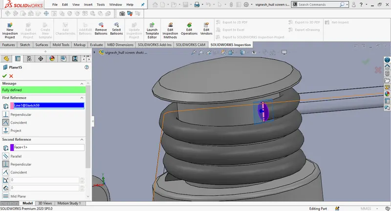
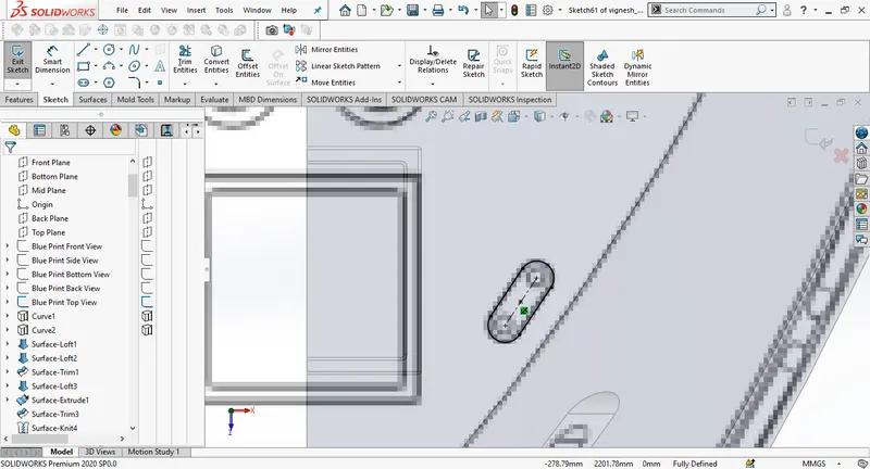
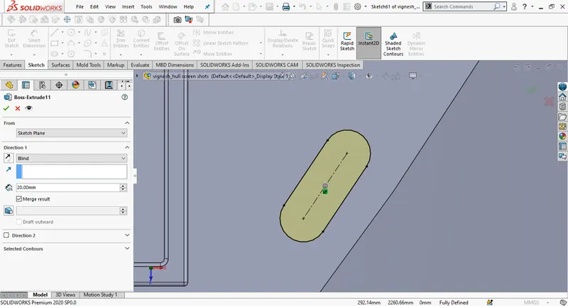
Draw a new 2D sketch on the top surface of the hull, create the portholes using slot . then extrude to 20mm distance, draw a new 2d sketch on the extruded surface, and then extrude .
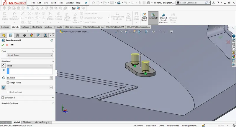
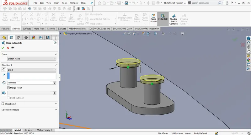
Fillet the eges and use linear pattern.
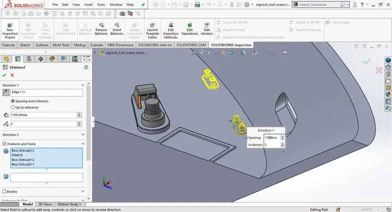
Draw a new 2D sketch on the top surface of the hull and extrude it using boss extrude. Then create the portholes by sketching on the extruded surface, Then use linear pattern to copy it.
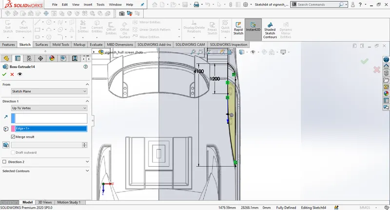
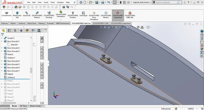
Draw the circles on the surface as showm in the images and extrude the sketch using boss extrude by selecting upto next option.
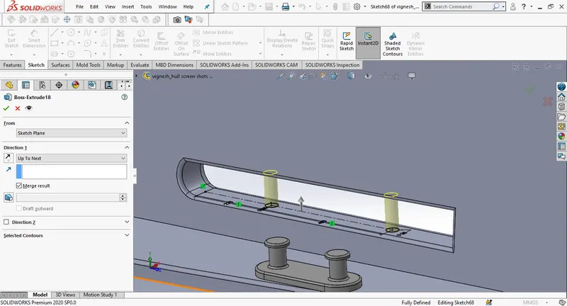
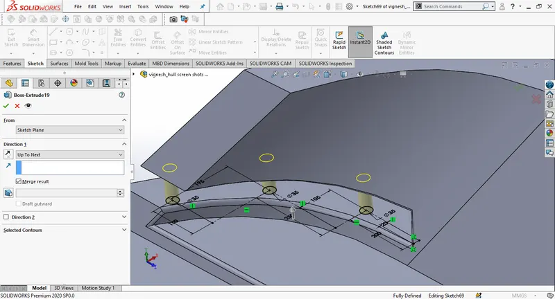
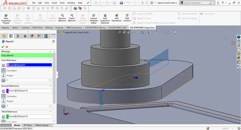
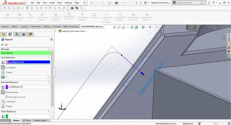
Create a new plane as in the image select the pink face as the first reference and give the offset distance of 50mm. and draw the new sketch on the new plane.
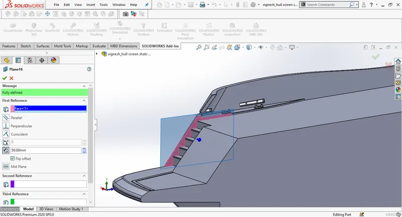
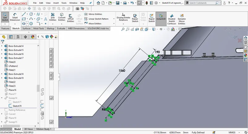
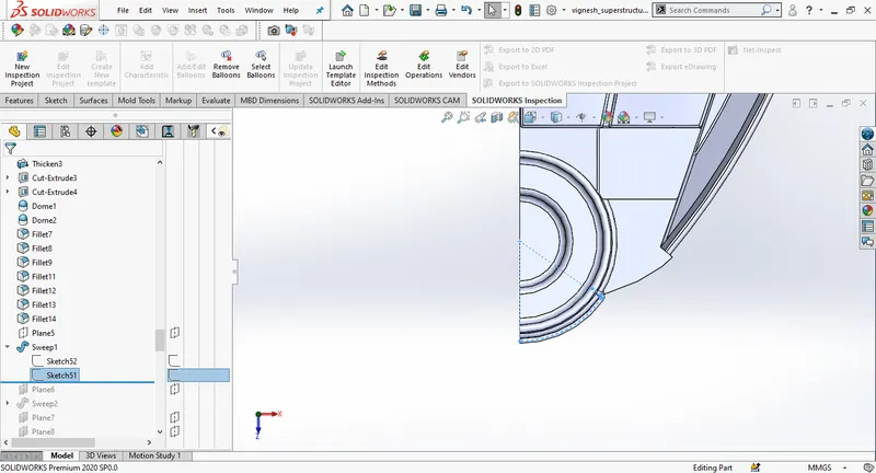
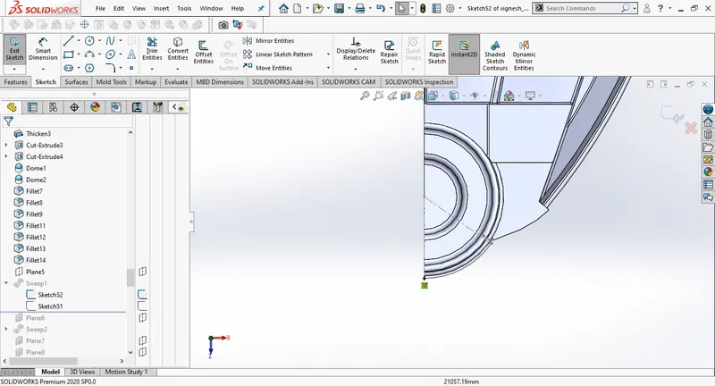
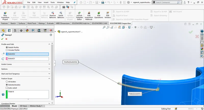
Create a new plane by selecting the end point of sketch 70 as referance. Draw a cercle on the new plane of radius 30mm and create a solid sweep.
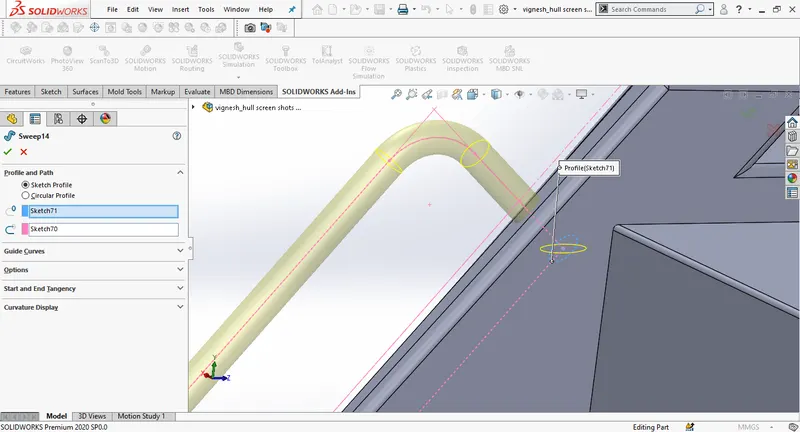
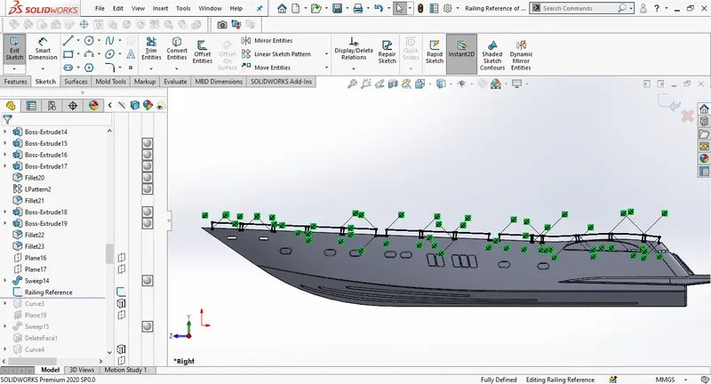
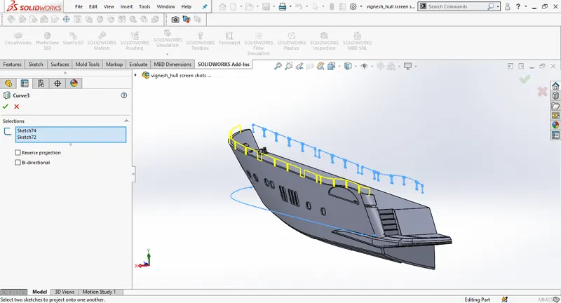
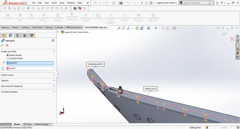
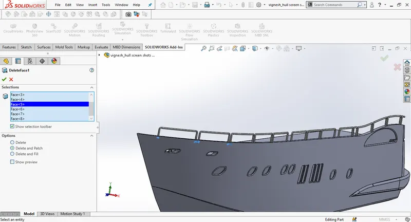
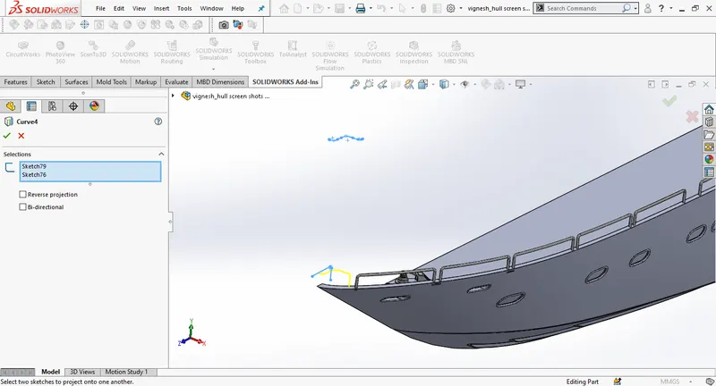
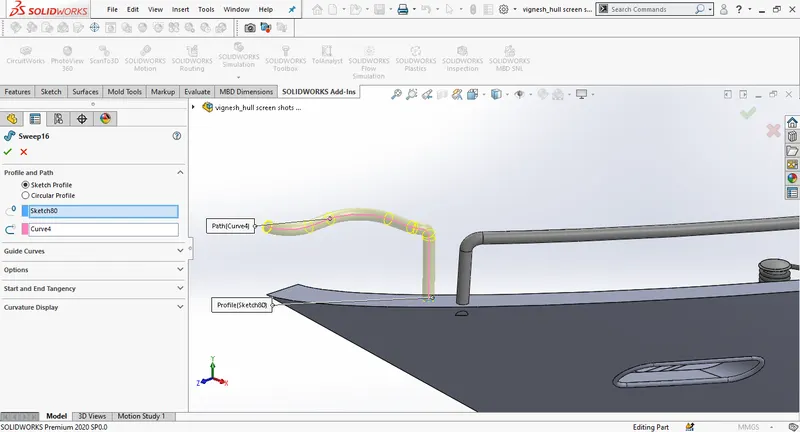
Draw a new sketch on midplane offset the edge of the hull to 70mm, using the blueprint side view make the sketch close to the blueprint, draw vertical line and trim the extra lines, sketch must to completly defines , manually fix the underdefined sketch, change the name of the sketch to railing referance, go to mid plane and use convert entities and convert railing referance to the sketch fillet the corners and exit the sketch, select top plane for new sketch offset the edge the hull, and exit. Use project curves to bothe sketchs. Create a new plane at the end of the curve, Draw a circle of width 60mm and use solid sweep.
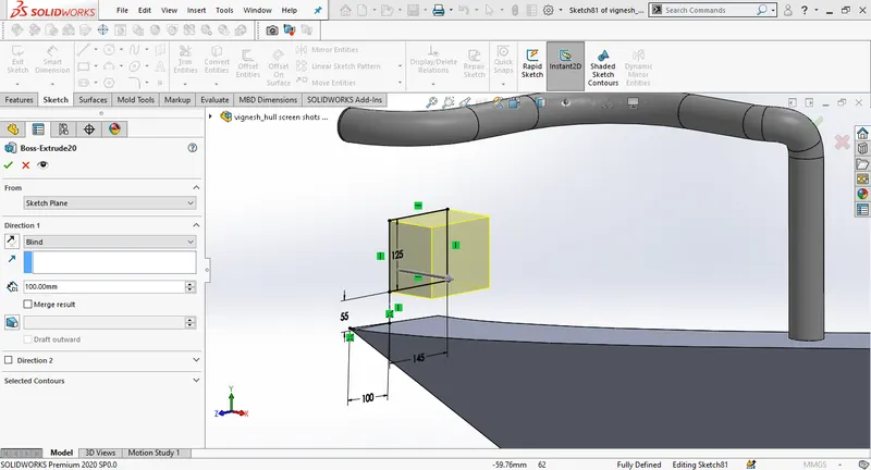
Draw a rectangle on the mid plane of lenght 125mm and width 145mm, 55mm above and 100mm aside from the corner vertex of the hull surface.Add fillets in the end.
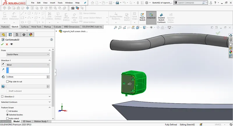
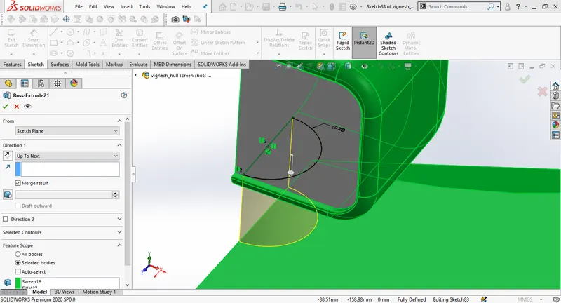
Draw a new sketch on the mid plane, create a new sketch on top plane and use project curves , create a new plane using the end point of the curve as the first referance.
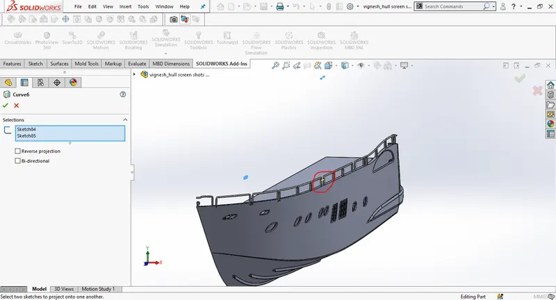
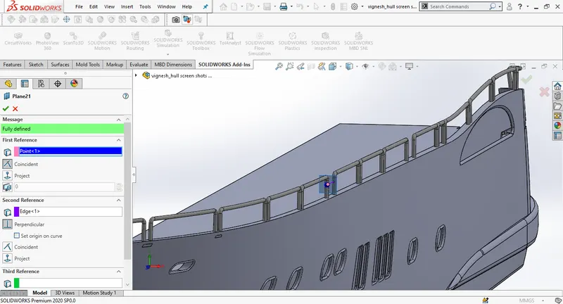
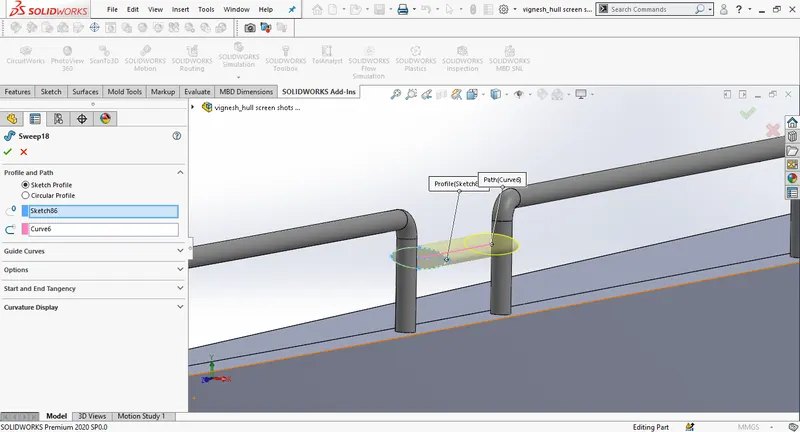
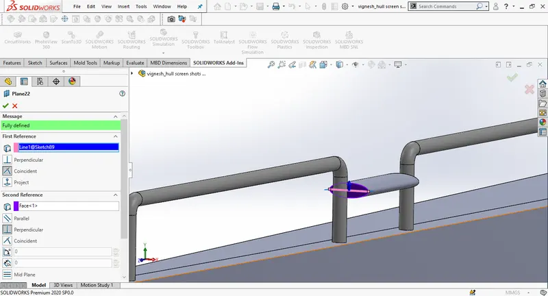
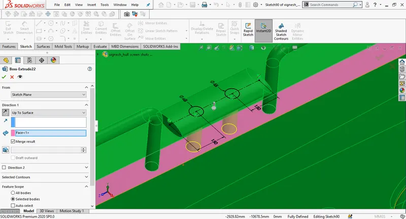
Model the trim tabs of the yatch by sketching on the back portion of the hull using the blueprint back view, define the sketch with proper dimensions, mirror the sketch by selecting the centerline and use boss extrude. Draw another skech on the bottom surface of the boss extrude.
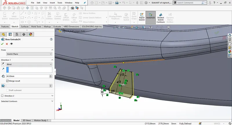
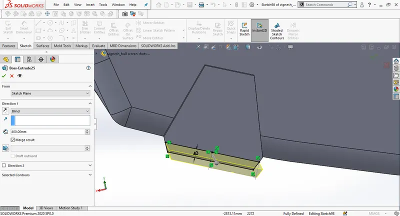
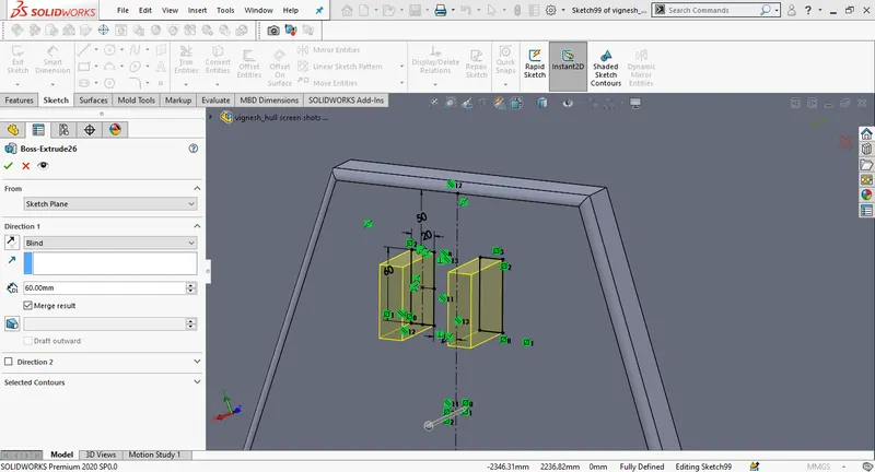
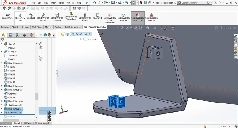
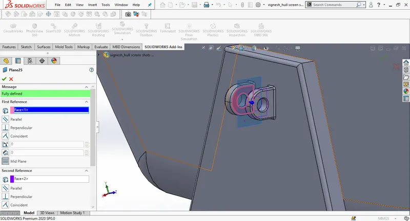
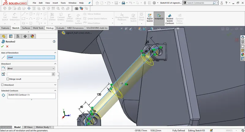
Unhide the blueprint side view, Draw a new sketch to model the shat for the propellers and use revolve choosing the center line as axis of rotation.
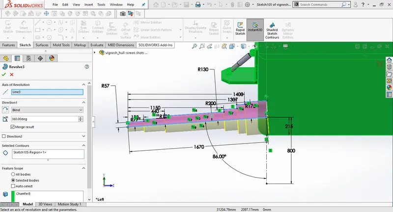
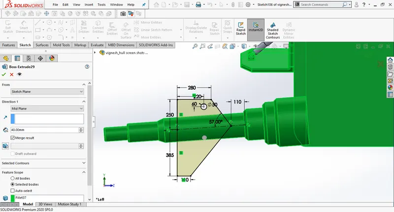
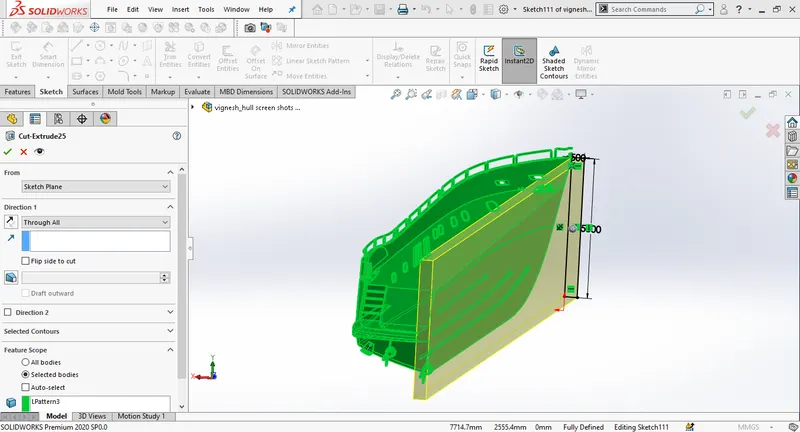
take a referance of a centerline and sue linear pattern to mirror the shaft. Then create a new sketch on the front plane. Then use extrude cut selecting through all.
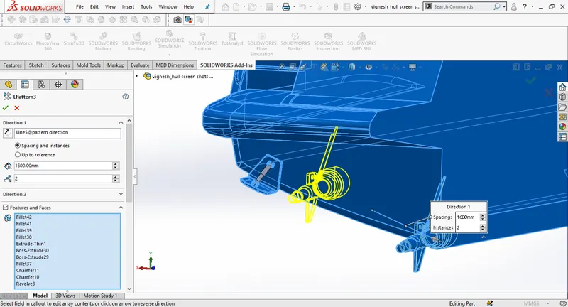
Draw a 3D sketch as shown in the picture, create a new plane selecting the 3D sketch end point as first referance and line as second referance.
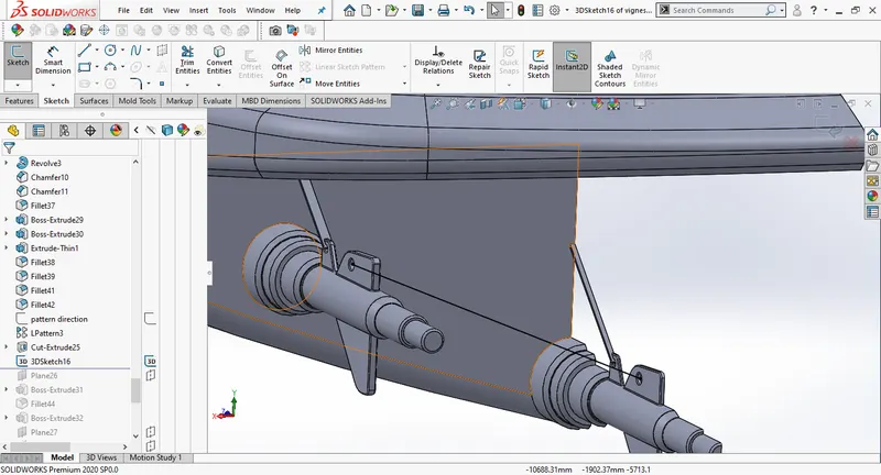
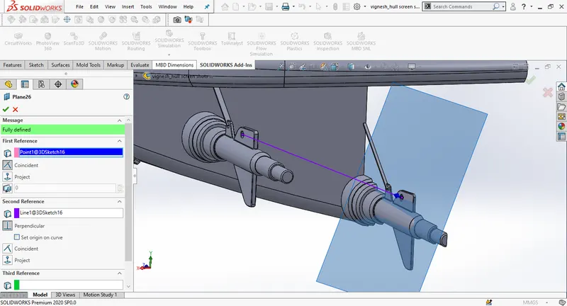
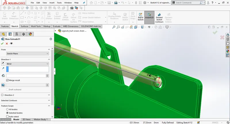
Draw a circle of diameter 40mm on the freshly created plane and extrude it to the distance of 1650mm.
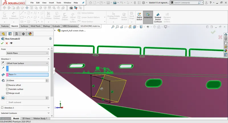
To model the anchor draw a new sketch on the midplane use extrude boss, select offset from the surface change the distance to 20mm. Then create a new plane selecting the vertex parallel to the hull surface. Again create a new plane with referance to the previous plane. Set offset distance of 50mm.
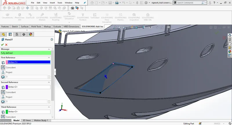
Draw a 2D sketch on the newly created plane,then select extrude, give required fillets and chamfer the edges as per the design requirments ,use mirror to create other half part of the anchor.
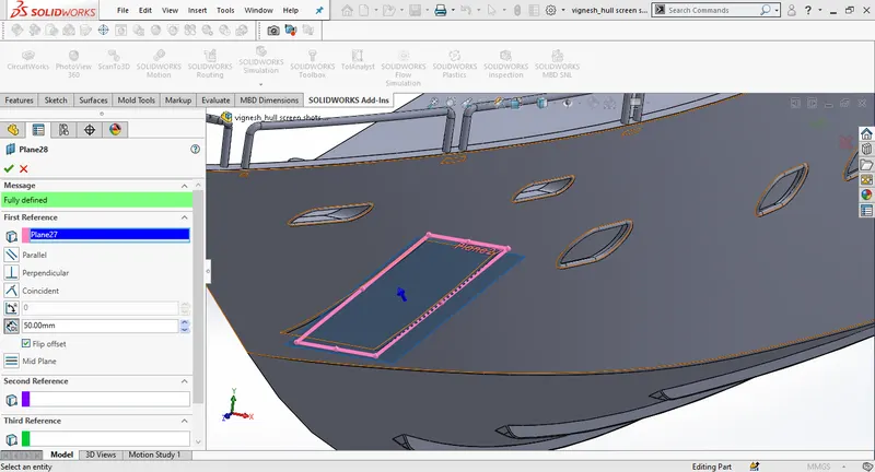
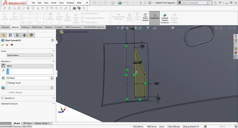
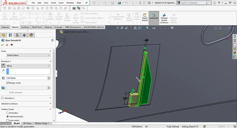
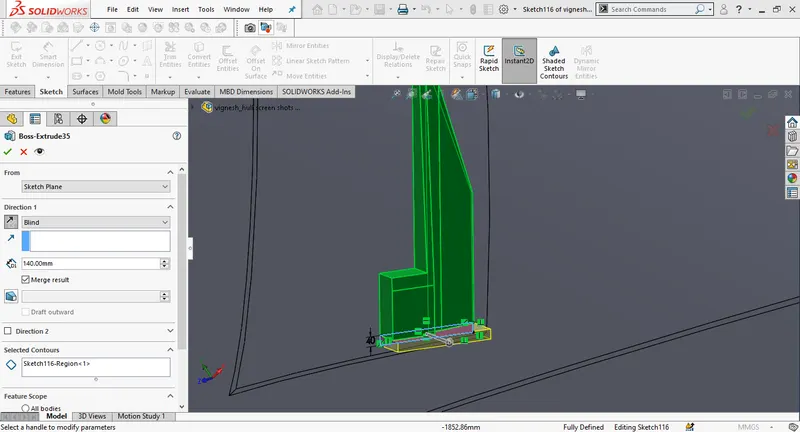
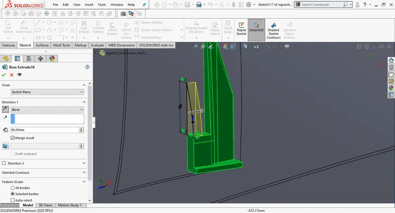
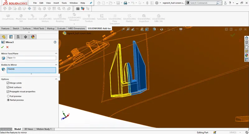
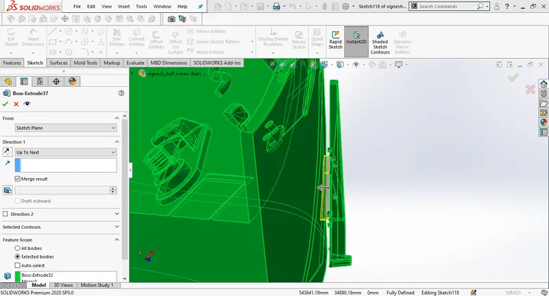
Create a thin cut extrude by sketching a corner rectangle on the midplane ,with 5mm thickness. create a new sketch using convert entities by previous cut extrude. use thin cut extrude with 5mm thickness, use split to saperate garage body from the hull.
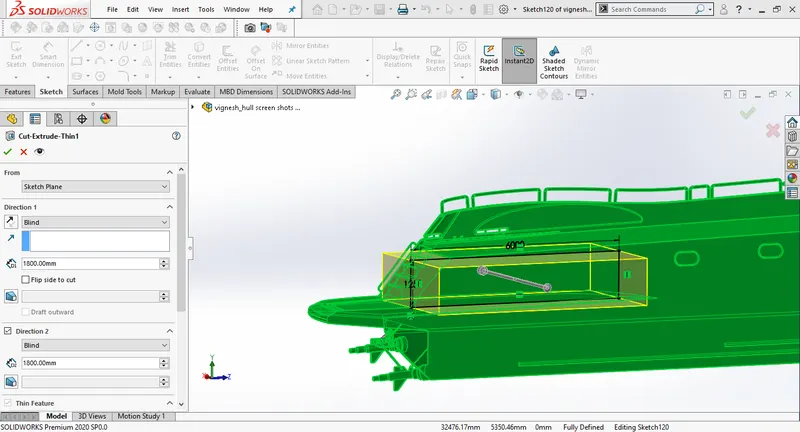
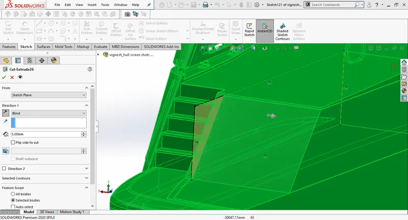
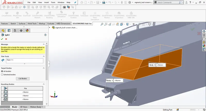
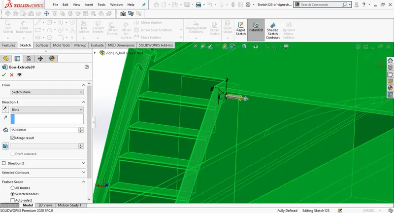
Create a new skecth on the mid plane and draw a spline close to the blueprint. offset the line above and below create split lines at the curve.
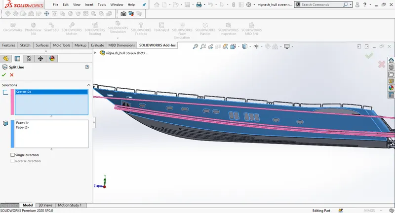
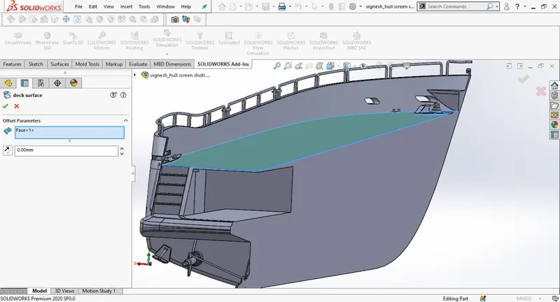
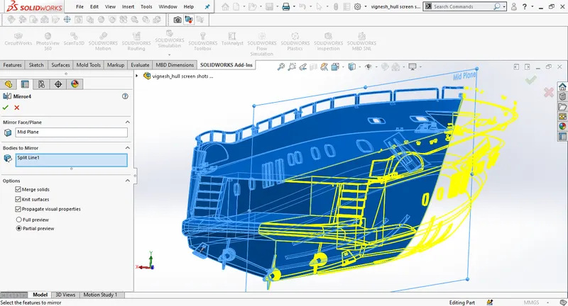
use deck surface to offset the surface of the hull and save it for the referance , add the appearances and mirror the bodies across the midplane.
GARAGE DOOR:
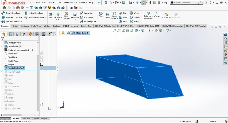
To model the garage door, open the exported body of the hull, draw a new 2D sketch on the side of the body, define the sketch with proper dimensions, create an extrude cut by selecting through all. Thn create a shell changing distance to 100mm. Give the fillets to finish the edges.
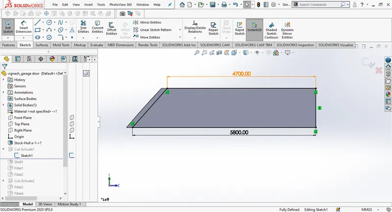
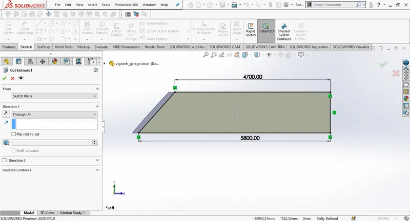
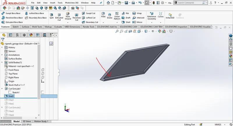
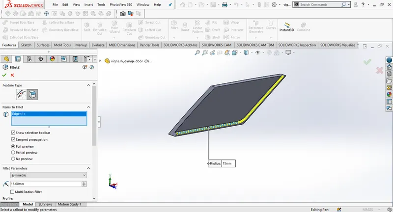
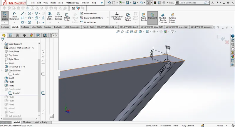
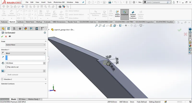
Draw a circle on the side of the door and create a cut extrude to the distance 100mm.
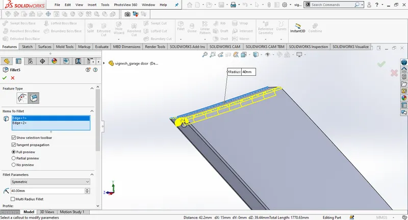
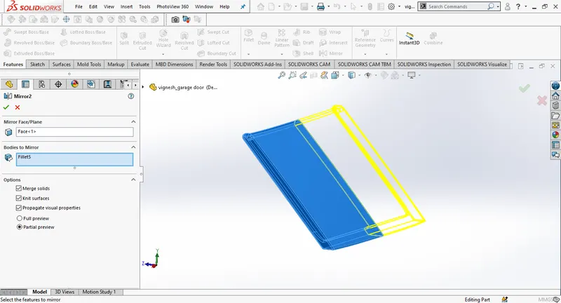
Use mirror pattern by selecting right plane as mirror plane select the body needed to be mirror, select merge results and knit surfaces click ok.
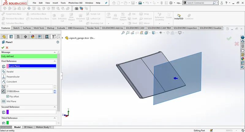
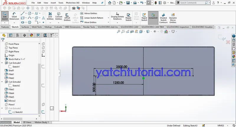
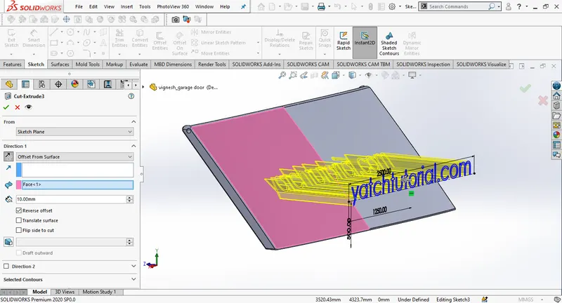
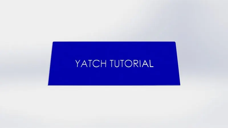
Insert a new plane using front plane as first referance. Create a new 2D sketch on the front plane, draw a centerline, insert a text using sketch tools and the centerline previously drawn, then exit the sketch and create a cut extrude, change the direction to offset from surface and change the distance to 8mm and select the door surface.
Add appearance at the end and finish.

FRONT SEAT:
For front seat, open the blueprint setup file and rename it as front seat, import the deck surface from the hull. Hide all the blueprint views except top view, select the deck surface and draw a 2d sketch. Match the sketch close to the blueprint, add dimensions to define the sketch.
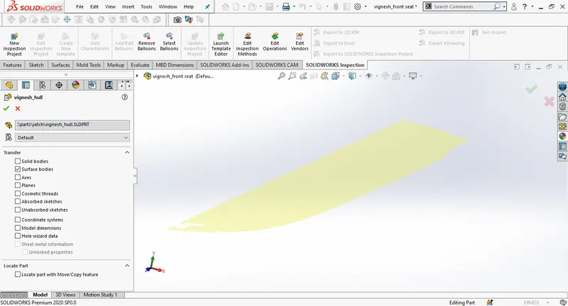
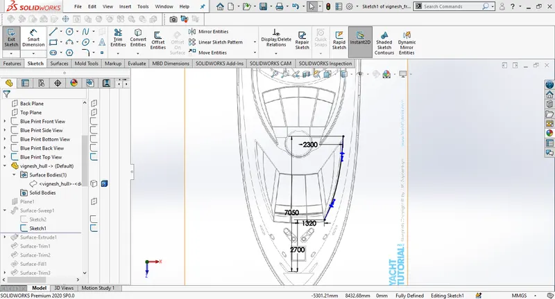
Insert the new plane selecting the spline as the first referance and its endpoint as second referance. Draw a new sketch on the new plane.
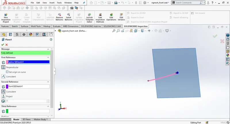
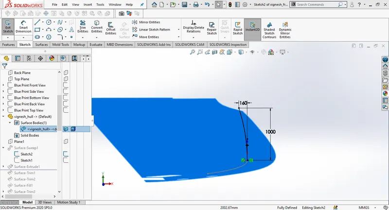
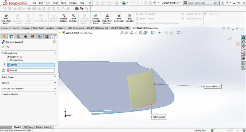
Create a surface sweep horizontal line a spath and vertical line as profile.
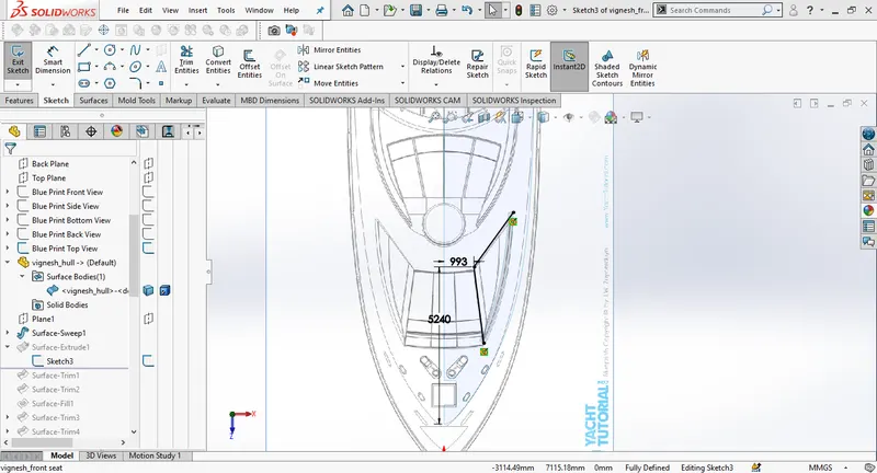
Draw two lines and add dimensions as in the picture, then create a surface extrude.Select the direction as upto vertex.
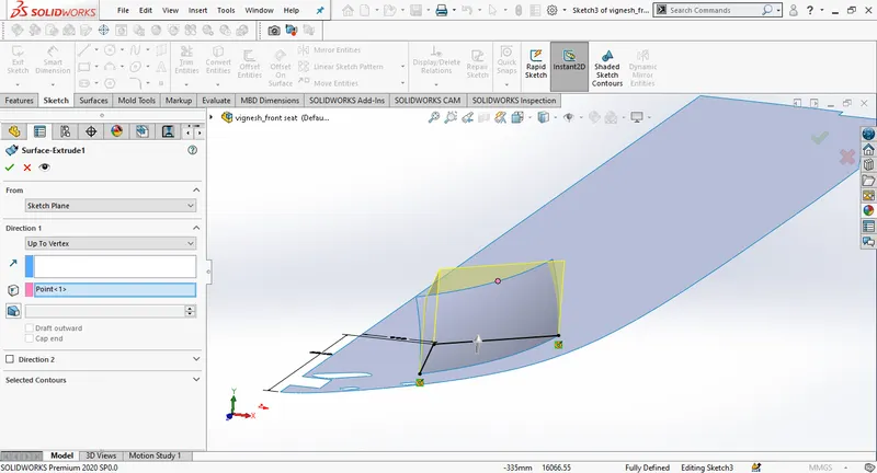
Trim the overlapping surfaces.
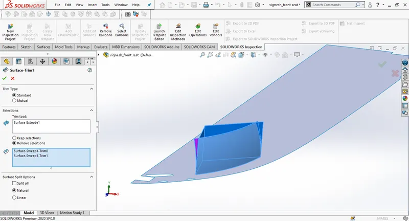
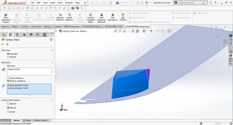
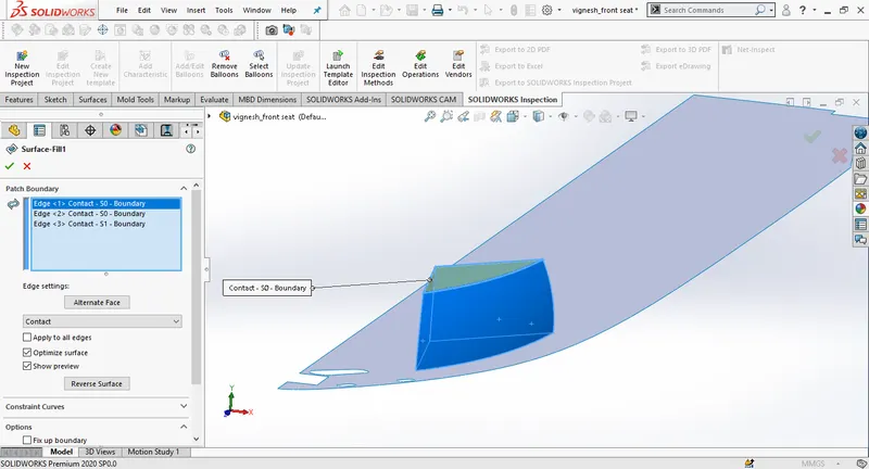
Create the surface fill and draw new sketch on the top sufrace. THen trim the surface.
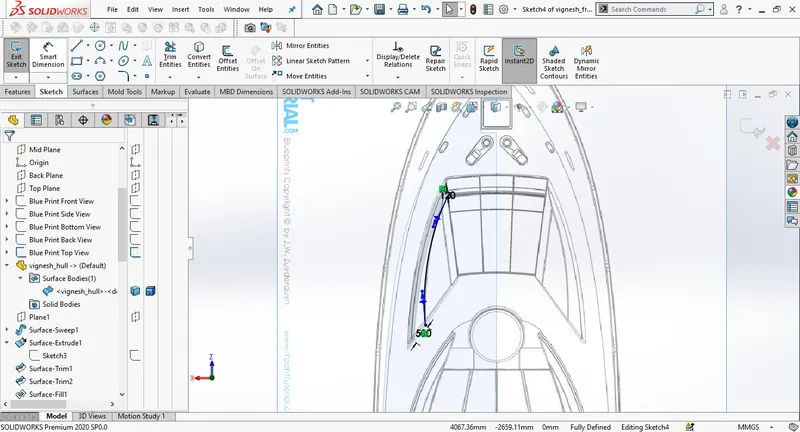
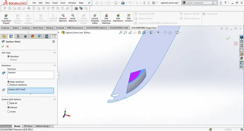
Draw a new sketch and add dimensions as in the image, then use trim to remove the surface.Create a surface loft selecting teo edges as loft profiles.
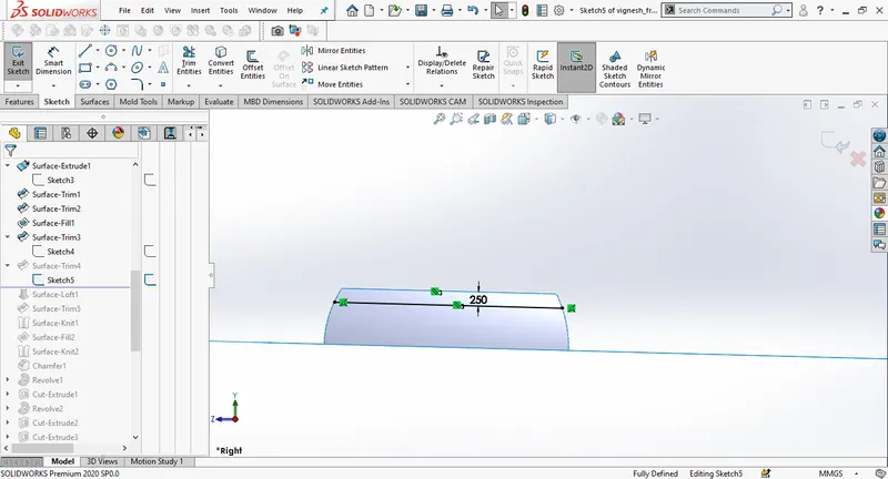
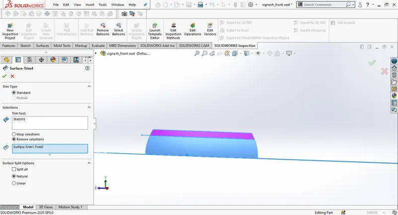
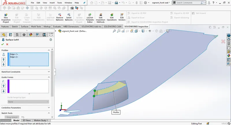
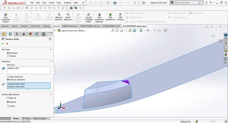
Knit all the surfaces together, hide the deck surface and use surface fill to complete underneath surface.
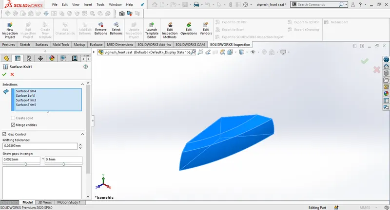
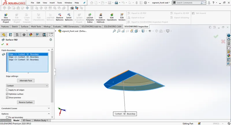
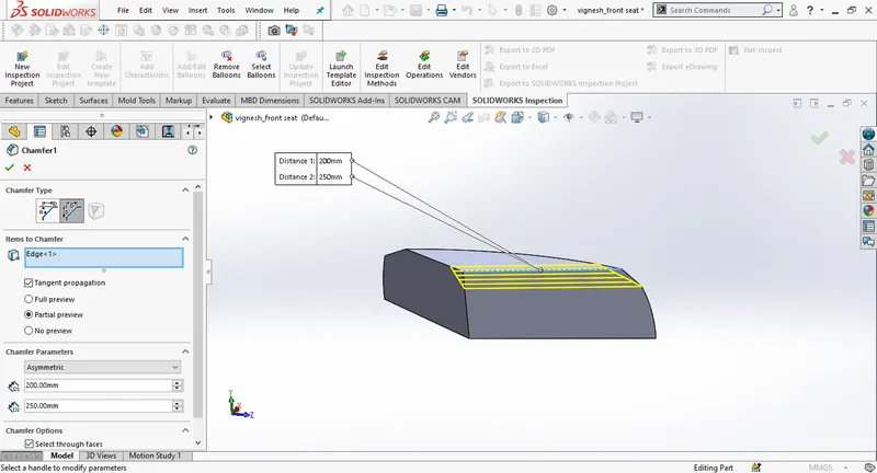
draw a new sketch on the side sufrace, use trim to remove the unwanted edges and then use revolve to finish.
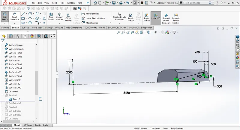
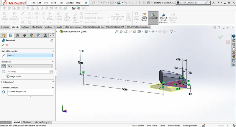
Draw a rectangle on the top plane and create a cut extrude.
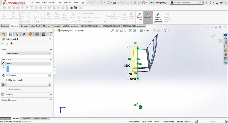
Create a new sketch and use revolve
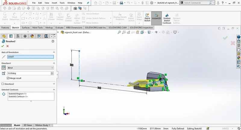
Create a new sketch on the top plane top plane, use cut extrude, change the extrude distance to 6000mm, make sure that the offset is facing towards down.Draw another sketch on the side surface use cut extrude and change the thickness to 5mm.
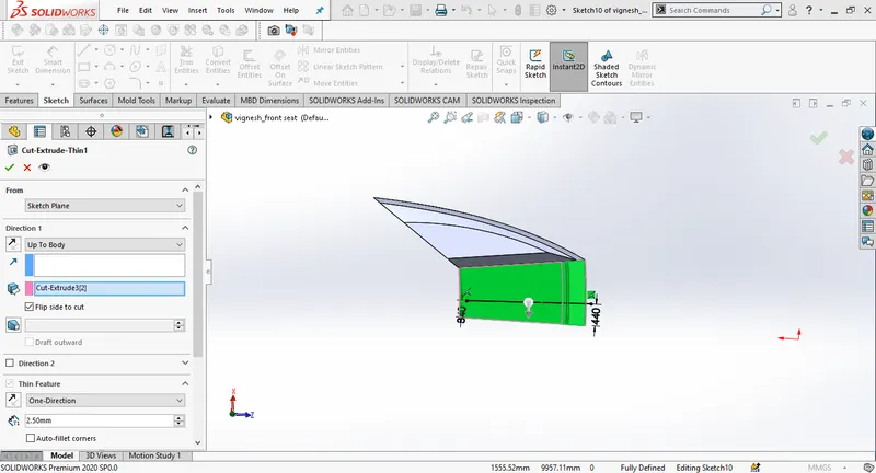
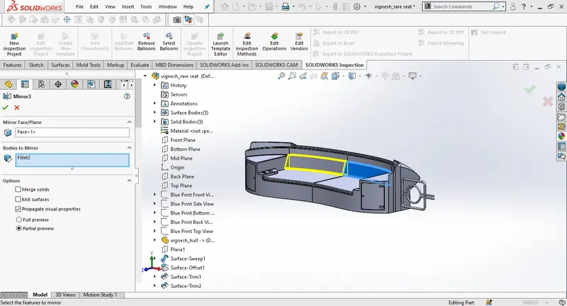
Mirror the center part of the front seat selecting the blue surface as mirror plane. Enable the knit surfaces and merge results.
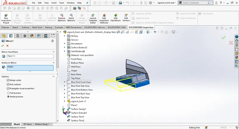
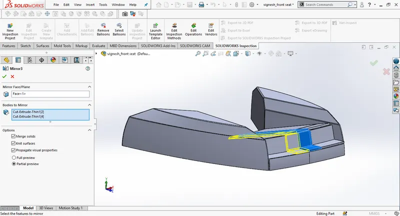
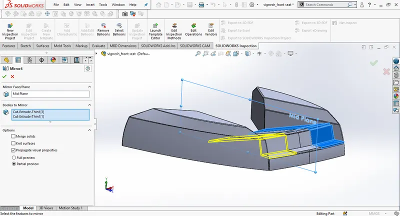
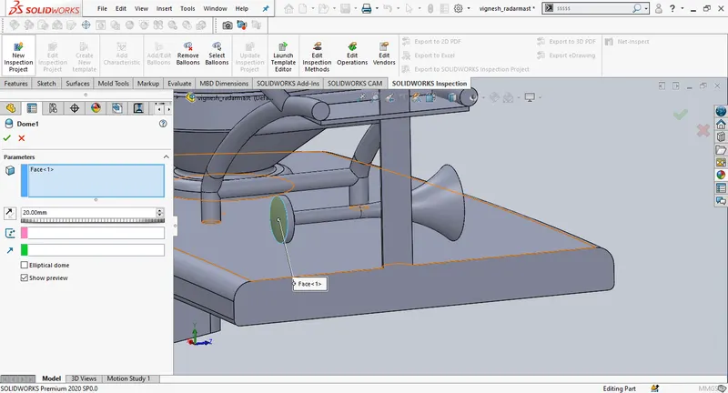
create a dome at the required areas as per the design
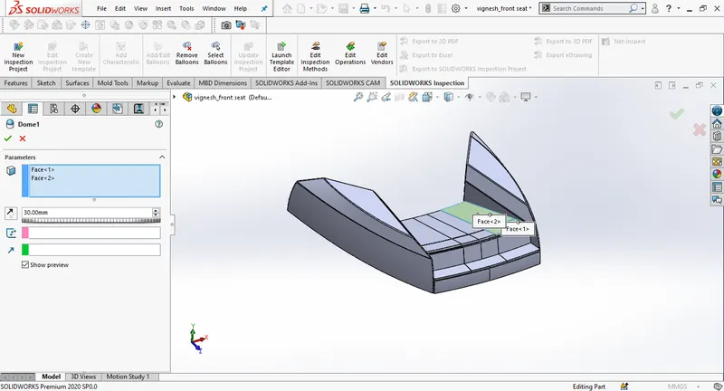
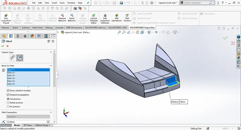
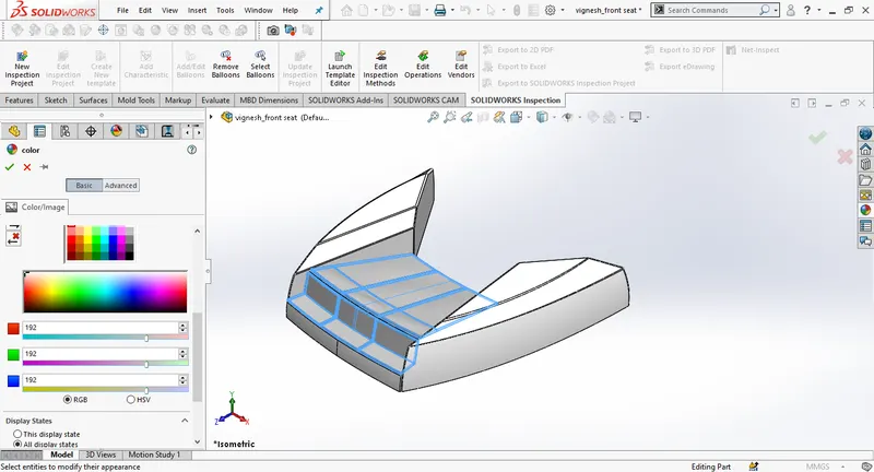
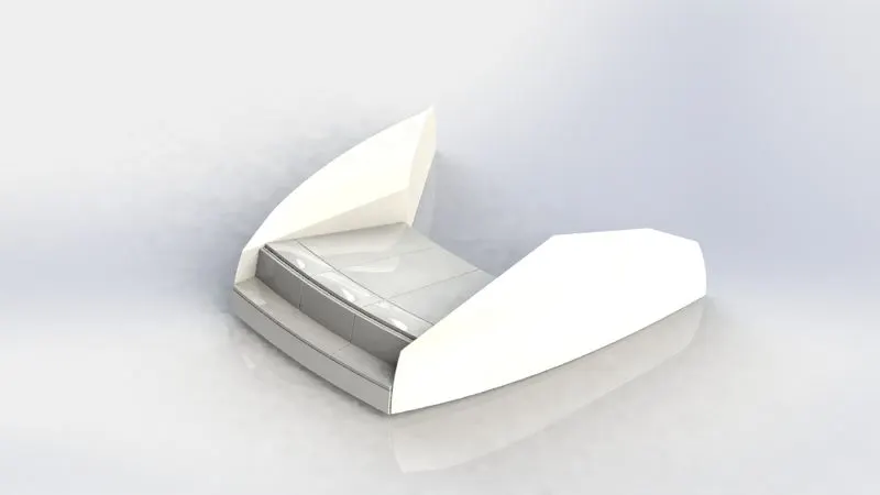
Add the appearance
MIDDLE SEAT:
For middle seat open the blueprint setup file and save the part file as middle seat. Then import the deck surface using insert, deselect all the options except the surfaces and click on ok. Hide all the blueprint views except the top blueprint view, select the deck surface and draw a sketch, add the dimensions and create an extrude using the sketch(depth 35mm).
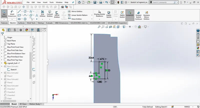
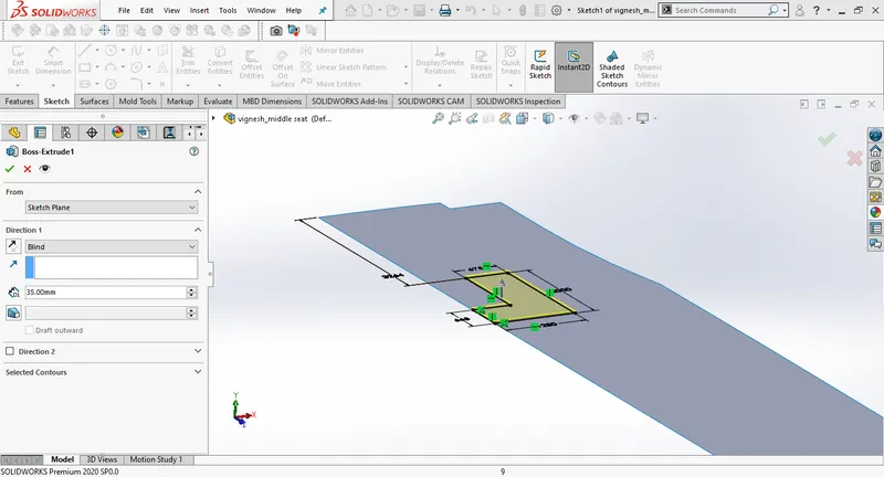
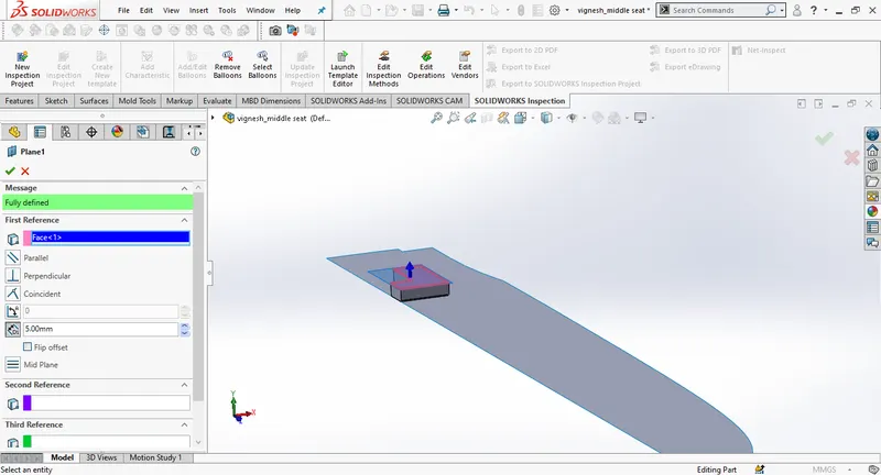
Draw a new sketch on the extruded surface using the offset edges , offsetting to 20mm, trim the upper part and complete the sketch using a line. Then create an extrude to 300mm. Create a new plane using the extruded surface as first referance.
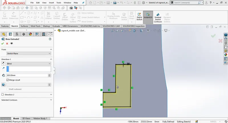
Create a new 2D sketch on the new plane and extrude it to 70mm towards up.
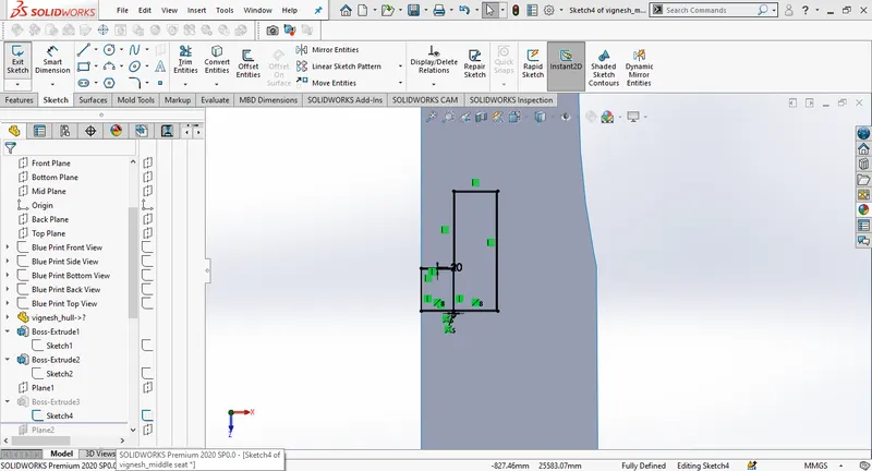
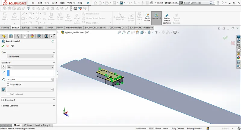
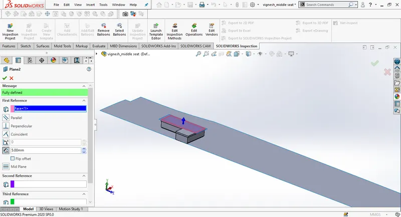
Again create a new plane using the surface of previous extrude as the first referance and 5mm as offset distance. Then create a new sketch on the plane 2 and make an extrude of 350mm.
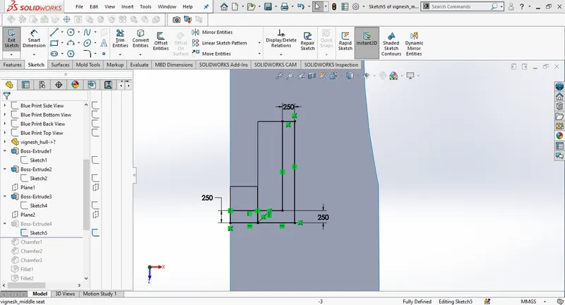
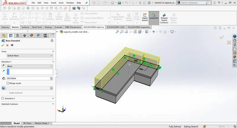
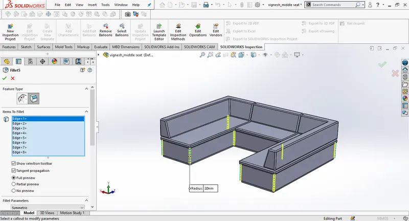
Create chamfers and fillets as per the design.
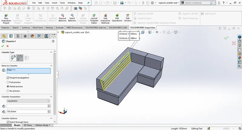
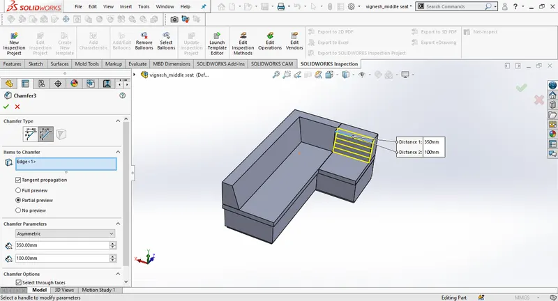
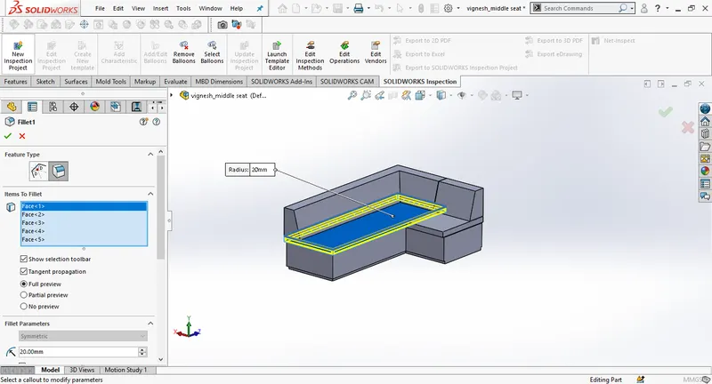
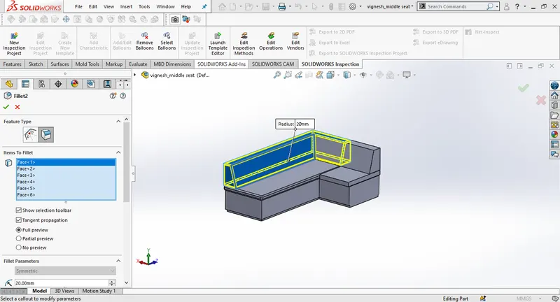
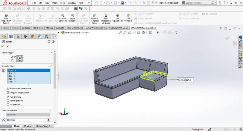
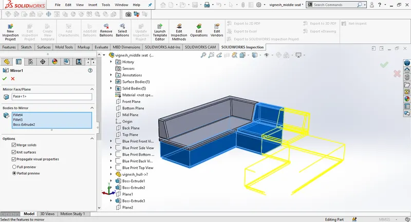
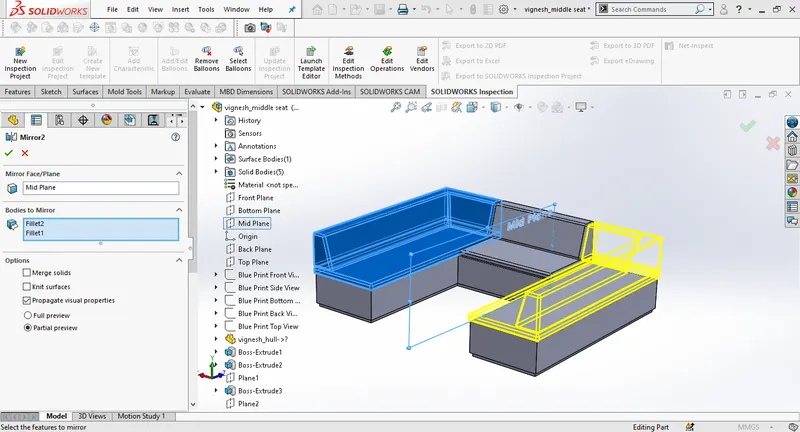
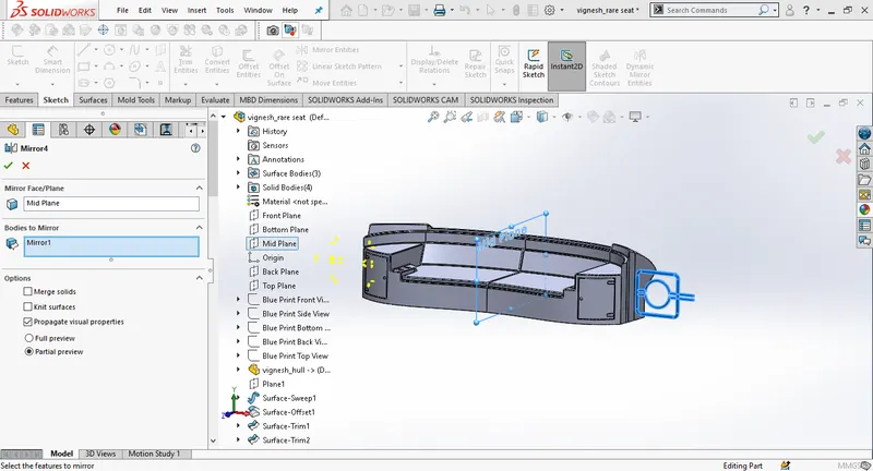
Mirror the bodies of the rear seat using midplane as the mirror plane.
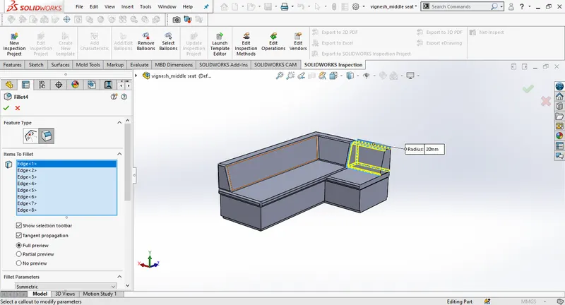
Add fillets to finish the main part of the rear seat.
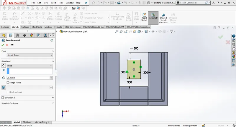
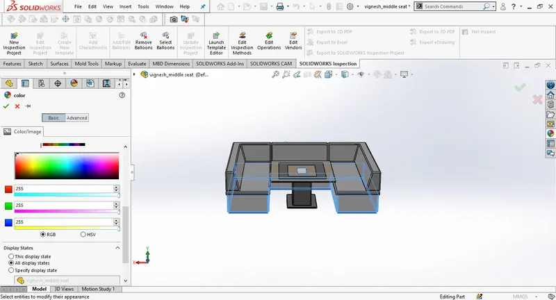
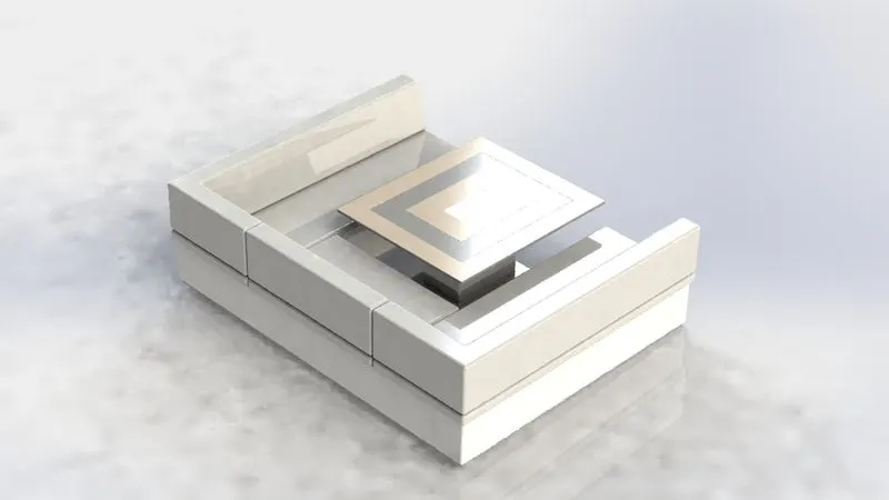
Draw a new sketch on the deck surface for table, draw a rectangle and give dimensions. Then extrude the sketch to 20mm upwards.
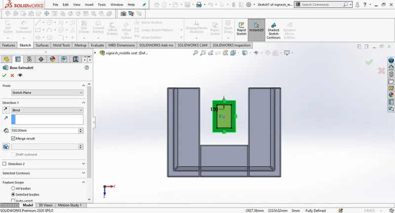
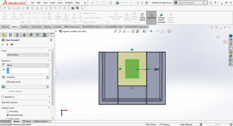
Draw a new sketch on the extruded surface. Use offest to draw the sketch offset inwards 100mm the edges of the previous extrude, Then extrude to 550mm. Repeat the same now this time offset edges of previous extrude to 395 mm towards outside and extrude it to 20mm.
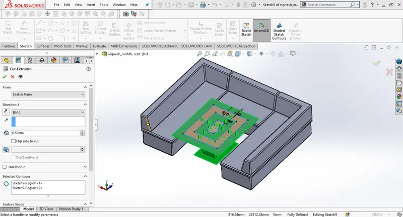
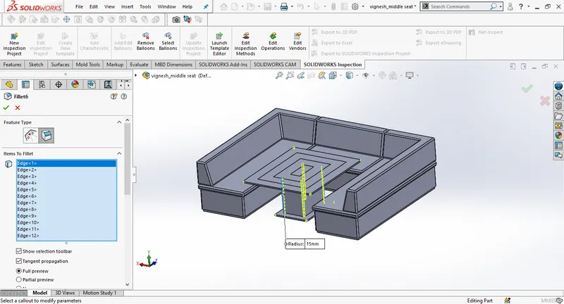
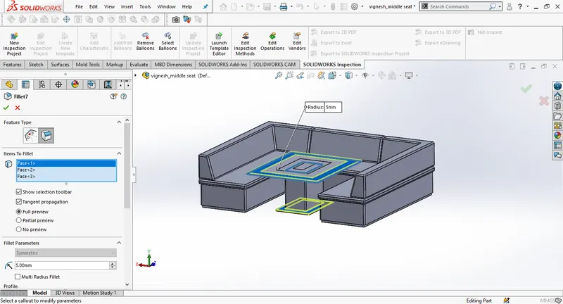
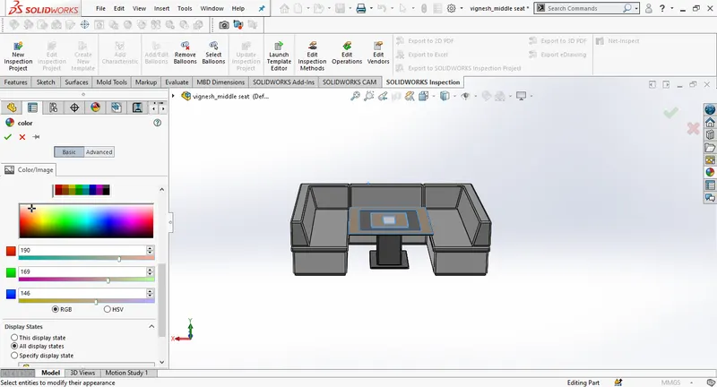
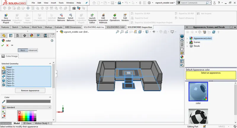
Create a new sketch on the recent extrude, Draw rectangles and give the dimensions, Use extrude cut change the depth to 0.50 mm. This gives more realistic look to the table. Give the fillets at the required areas to finish. Then add appearances in the end.
REAR SEAT:
To design the rear seat import the deck surface of the hull as interface surface.
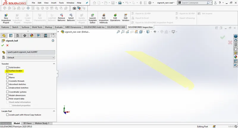
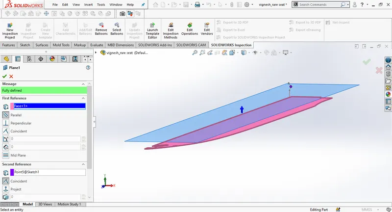
Insert the new plane as deck surface as referance.
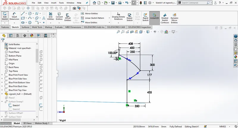
Select the mid plane and draw a 2D sketch and give dimensions to sketch.
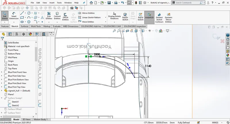
Create a new sketch on the plane 1,using the spline handles adjust the curve close to blueprint.
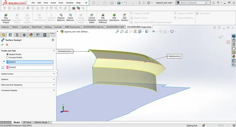
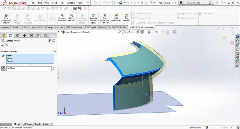
Create a surface sweep usiing sketch 1 as profile and sketch 2 as path and then create a surface offset to the swept surface, give the offset distance of 50mm towards outside.
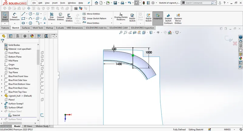
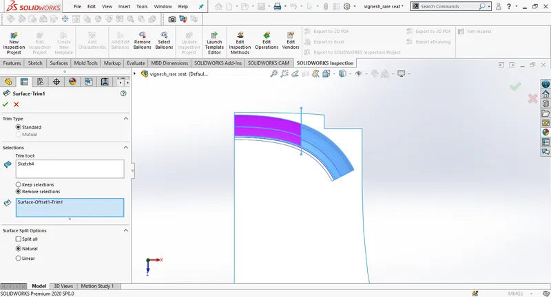
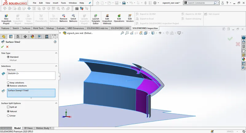
Draw a 2D sketch on the plane1. Use surface trim and select new sketch as trim tool, make sure to enable the remove selections.
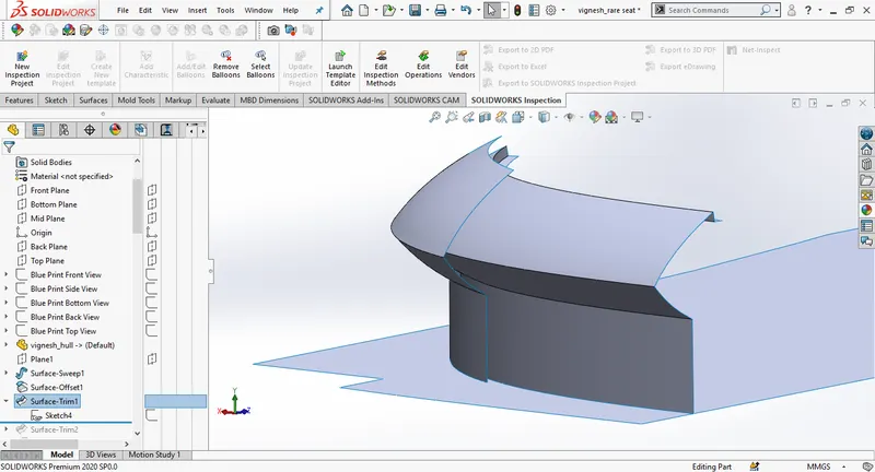
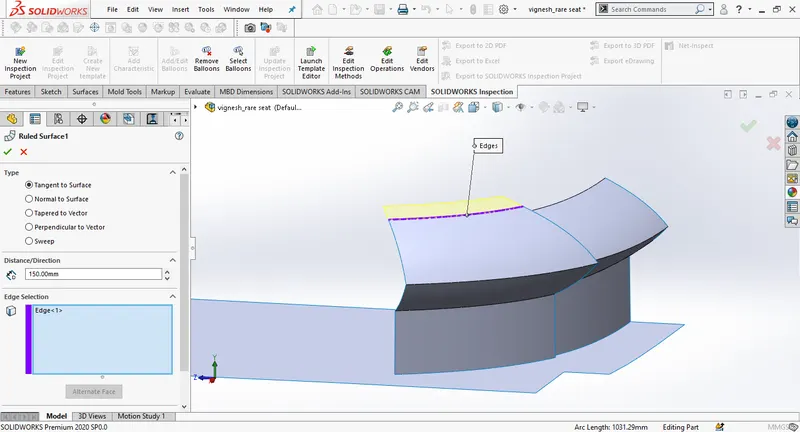
Create a ruled surface, select tangent to surface option, select the edge and change the dimensions to 150mm. Knit the surfaces together.
Draw a new sketch on plane1. Trim the surface using surface trim and new sketch as trim tool and enable remove selection.
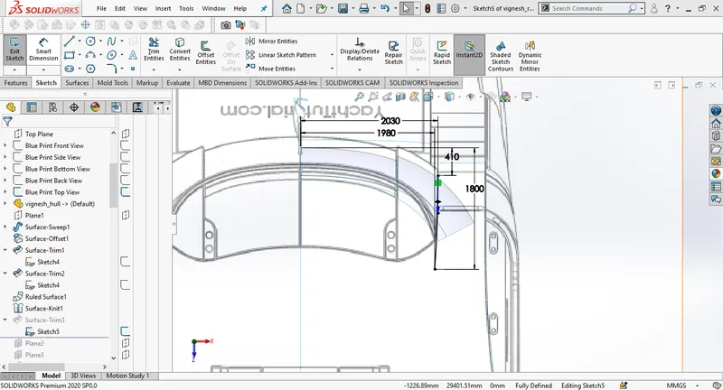
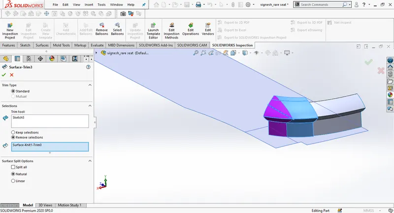
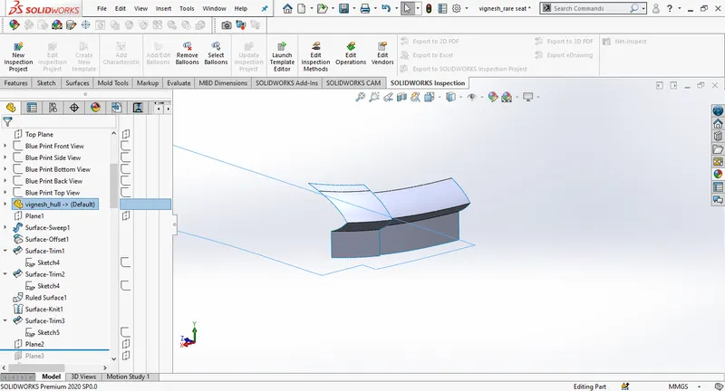
Create a new plane. Draw a 2D sketch on the new plane.
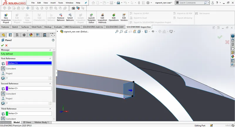
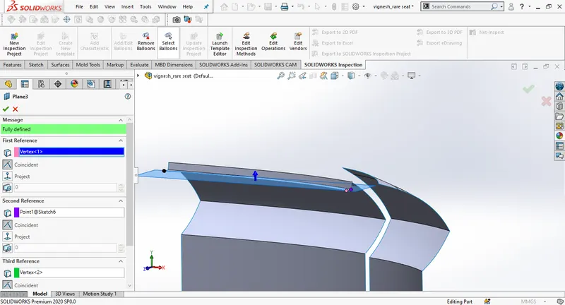
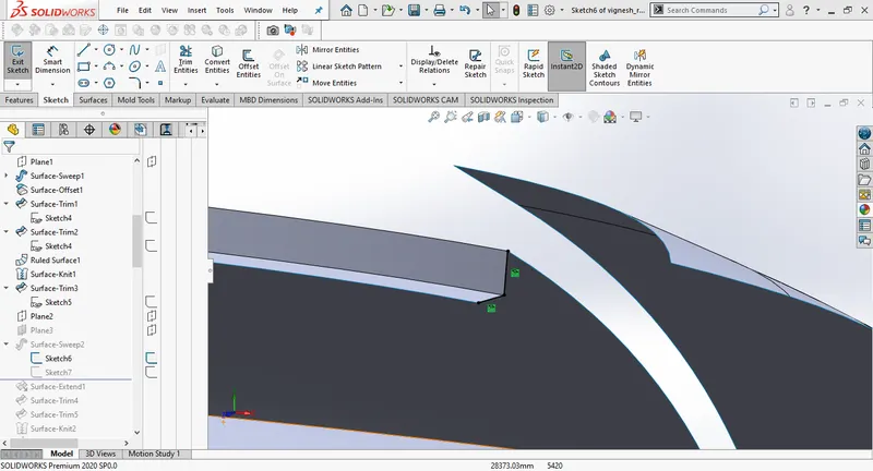
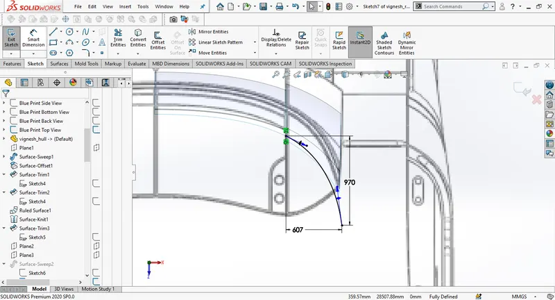
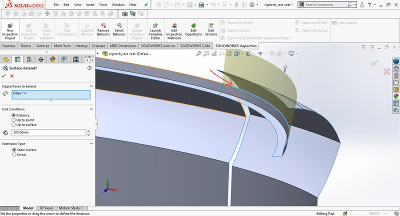
Create a surface sweep and then extend the surface of surface sweep.
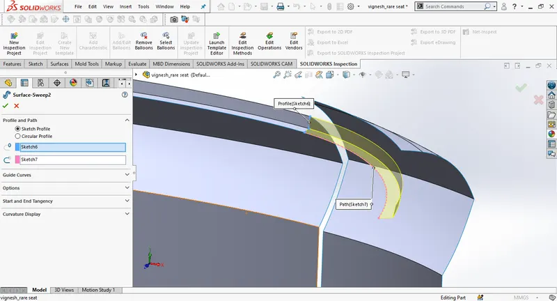
Use surface trim to remove the overlapping surfaces. Knit the surfaces.
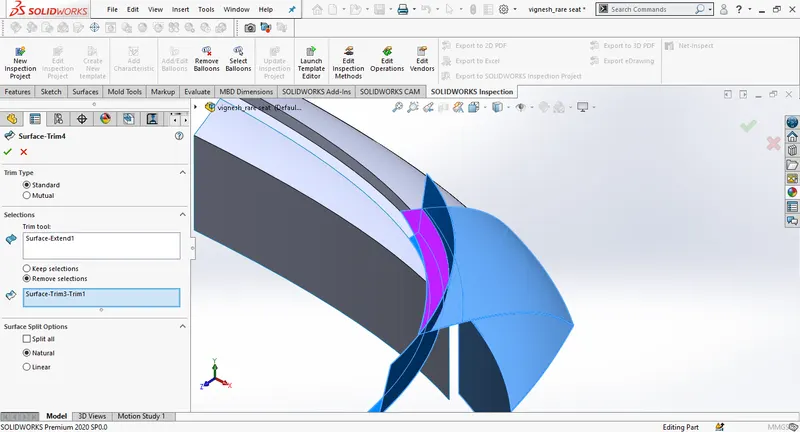
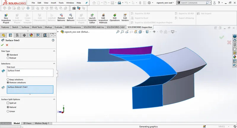
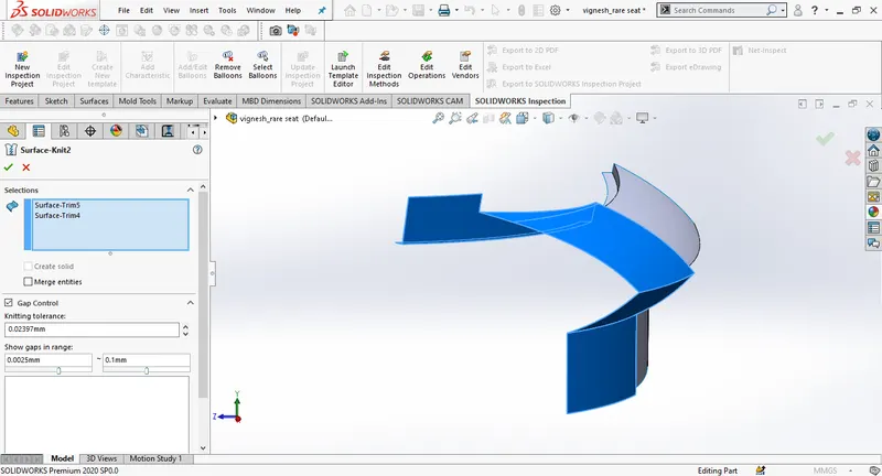
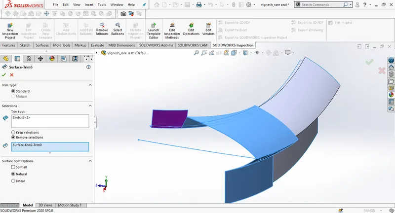
Draw a new 2D sketch on the deck surface, sue convert entities to convert the edge. Create a surface extrude using the sketch and trim the extra part. Knit the surfaces together.
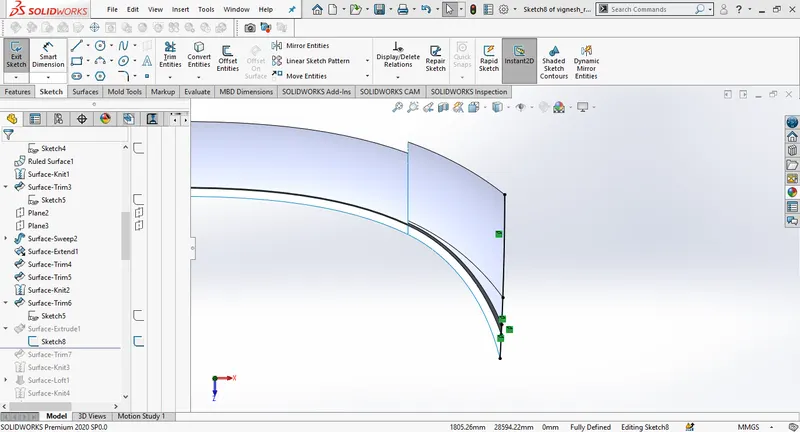
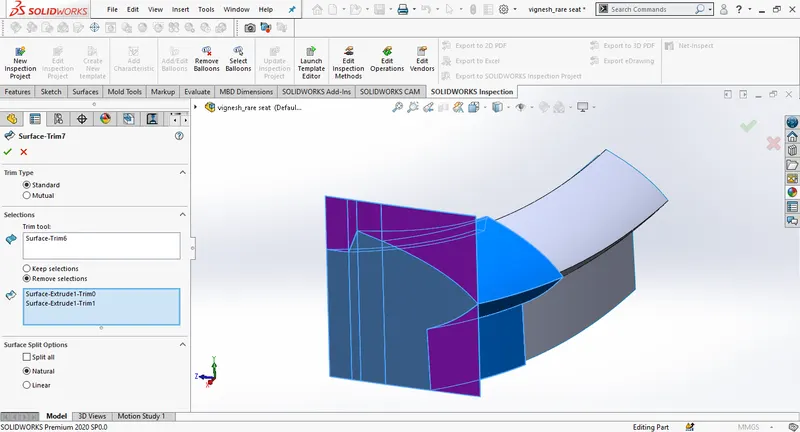
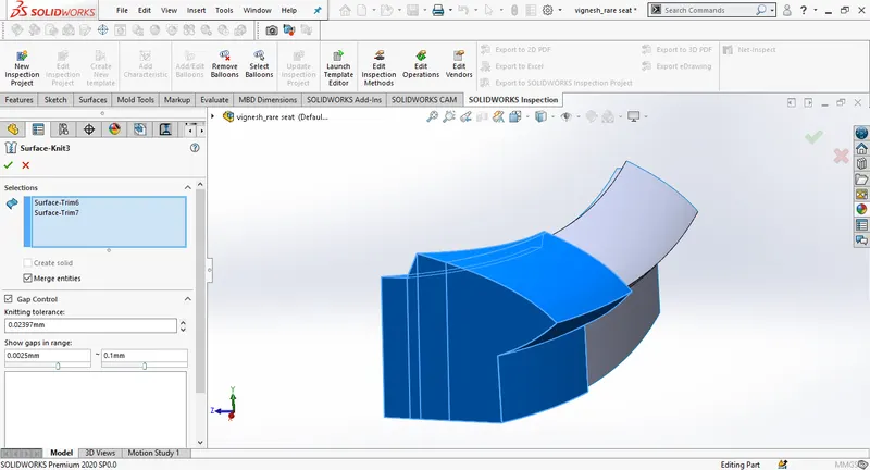
Draw a 3D sketch using convert entities, Do the same with the other edge, and then create a surface loft using 3Dsketch1 and 3Dsketch2 as profiles. Knit the surfaces together in the end.
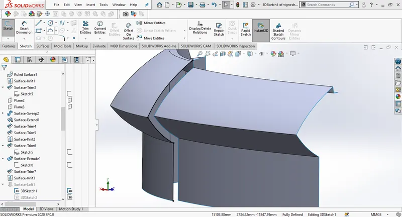
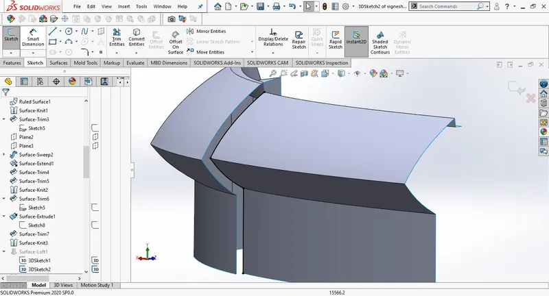
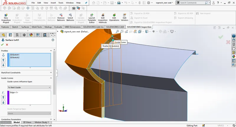
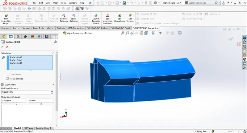
Create a new sketch on the deck surface select the edge and use convert entities to make a 2d sketch. Then use surface extrude, select the direction as upto surface.
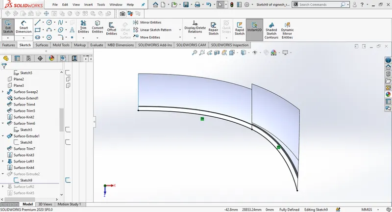
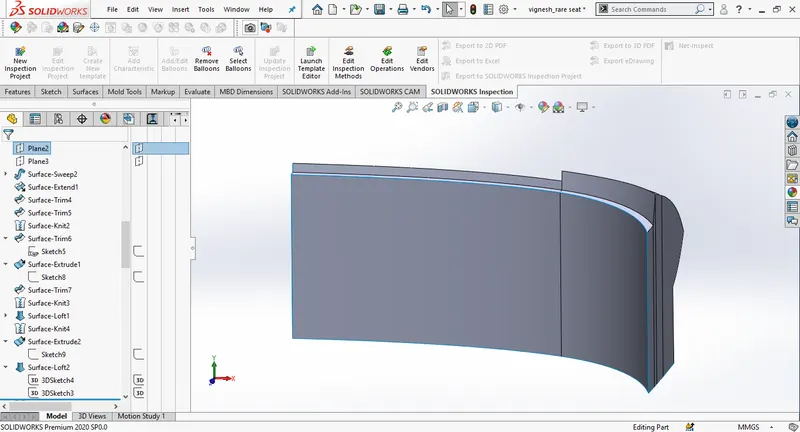
Create a new 3Dsketch and use surface loft to close, Knit the surfaces together.
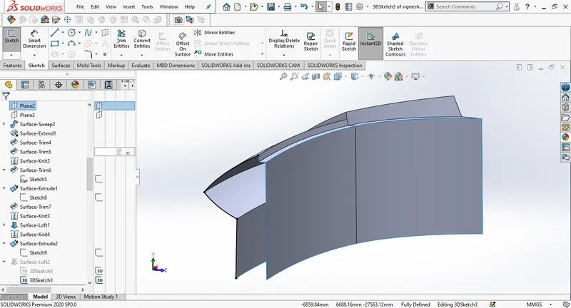
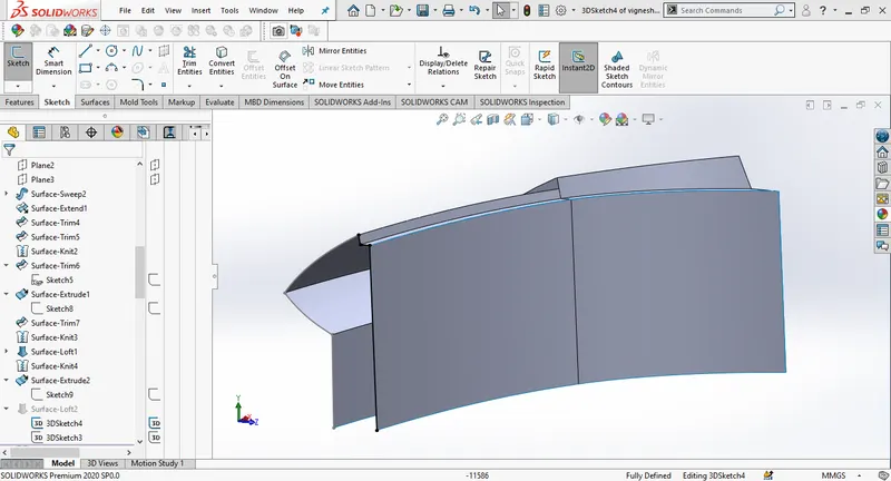
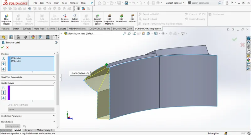
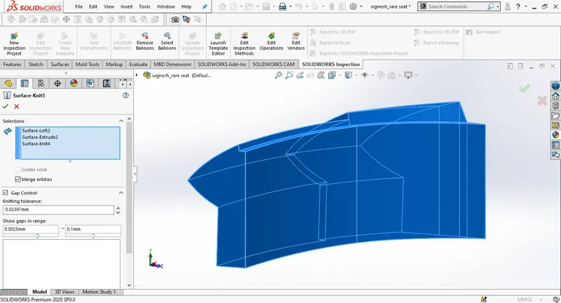
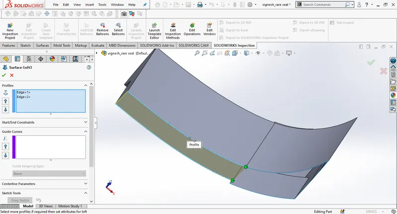
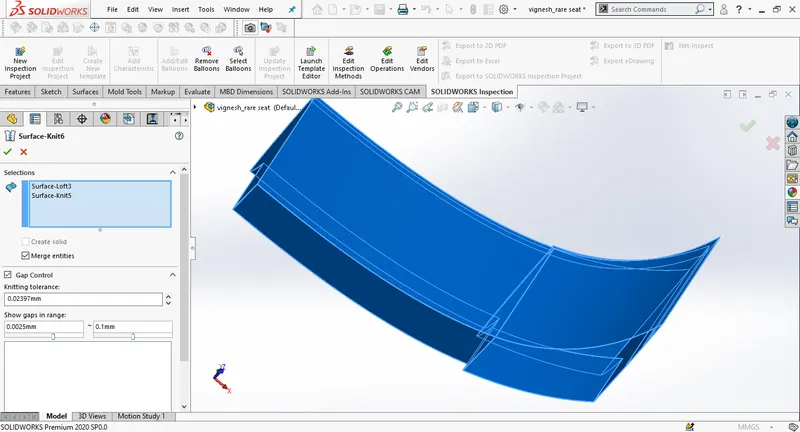
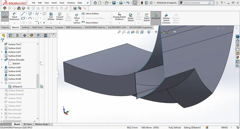
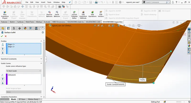
extend the surface and trim the extra edges to fill the gaps.
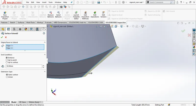
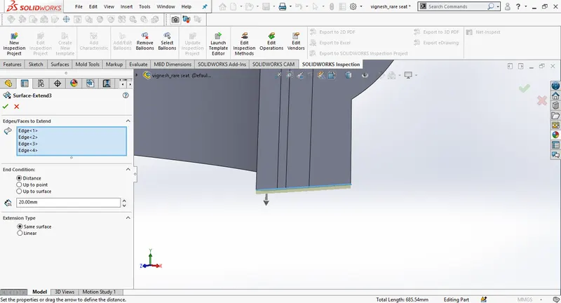
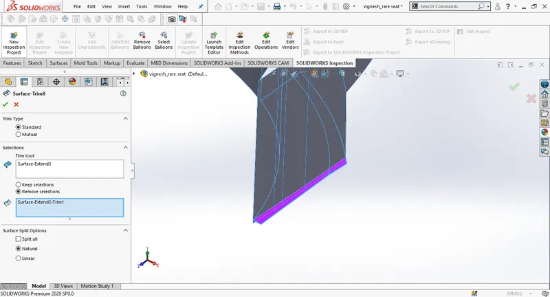
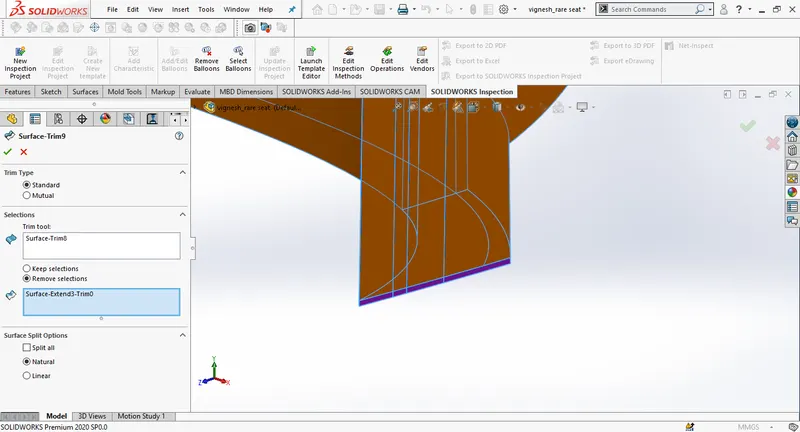
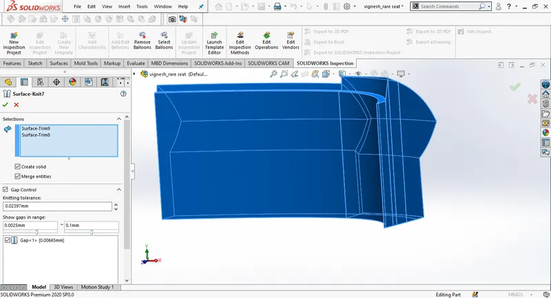
knit all the surfaces together make sure it results black edge lines, otherwise check if there are any gaps.
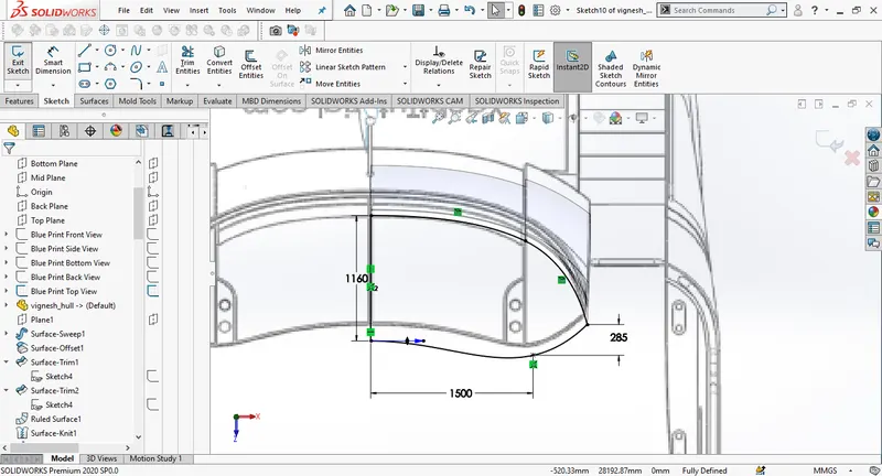
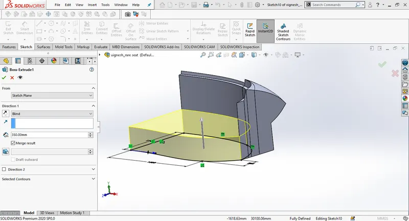
Draw a new sketch on the deck surface. use convert entities to draw the sketch. Use blueprint top viw to draw the sketch and make the sketch close to the blueprint, then extrude the sketch upwards to 350mm. Then draw another sketch on the extruded surface, and extrude.
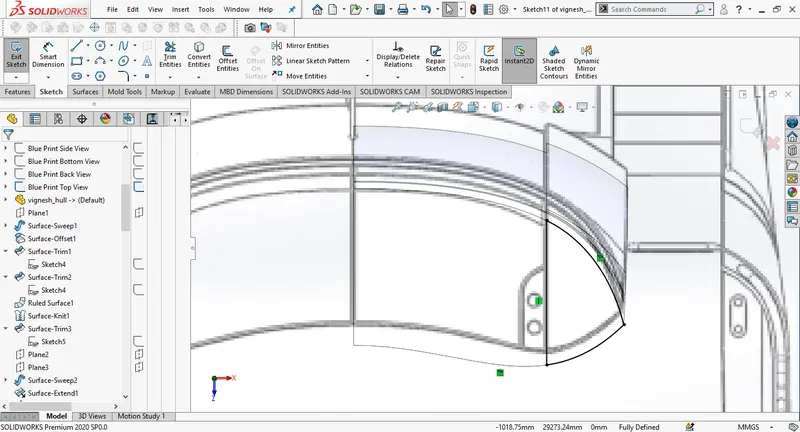
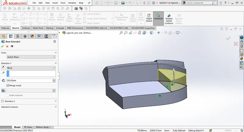
Draw a new sketch on the front plane draw rectangle and give dimensions, offset the sketch inwards to 5mm. Then make an extrude cut select the direction as offset from the surface and change the distance to 50mm.
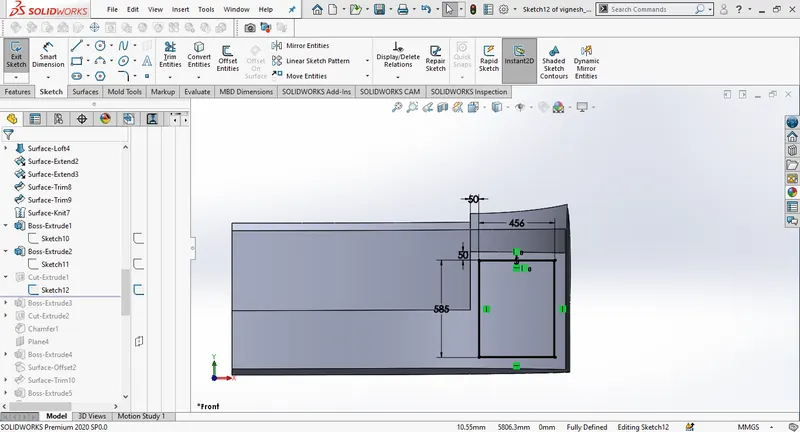
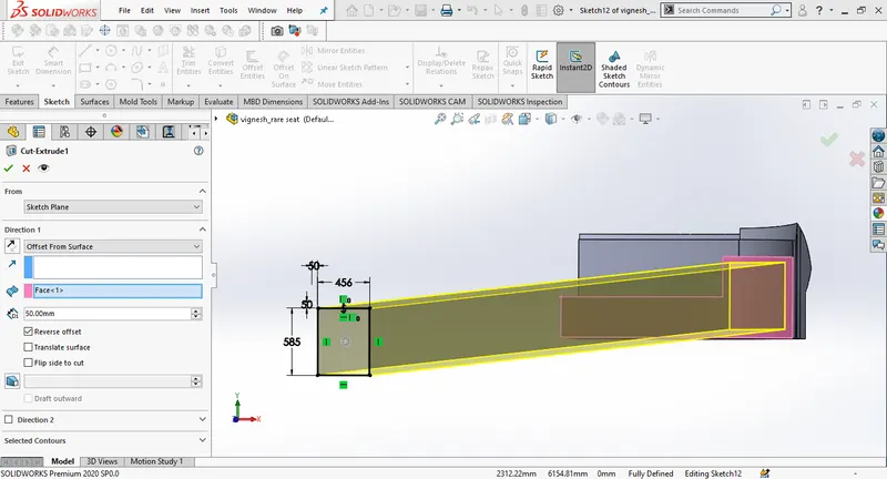
Draw a new sketch on the horizontar surface of the rear seat, and create an extrude towards upwards and distance of 120mm. Draw circles on the extruded surface and make an extrude cut selecting the sketch and change the distance to 90mm.
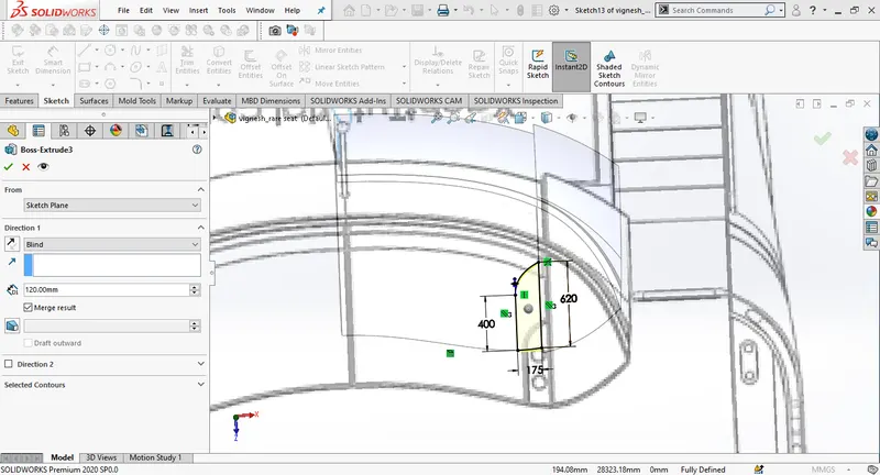
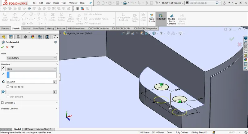
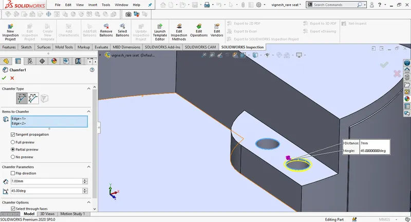
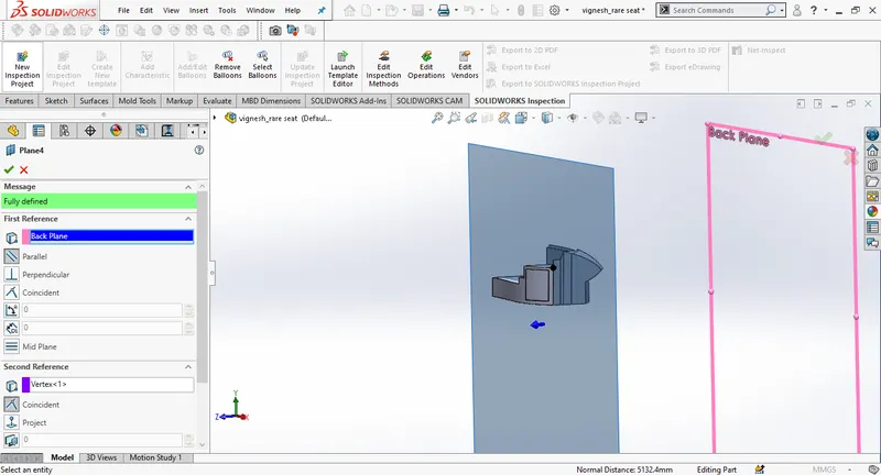
Create a new plane as selecting the back plane as first referance, and the black vertex as second referance. Draw a new sketch on the new plane and make a boss extrude. change the distance to 5mm.
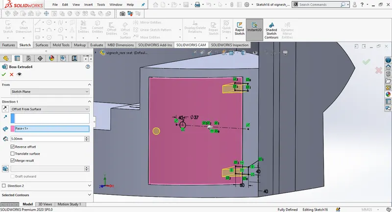
Create a surface offset and give the offset distance of 5mm, draw a new sketch on the new surface, use offset entities and give the offset distance as 2.5mm towards inwards, Trim surface selecting keep selection.
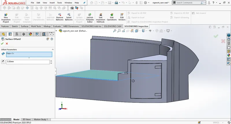
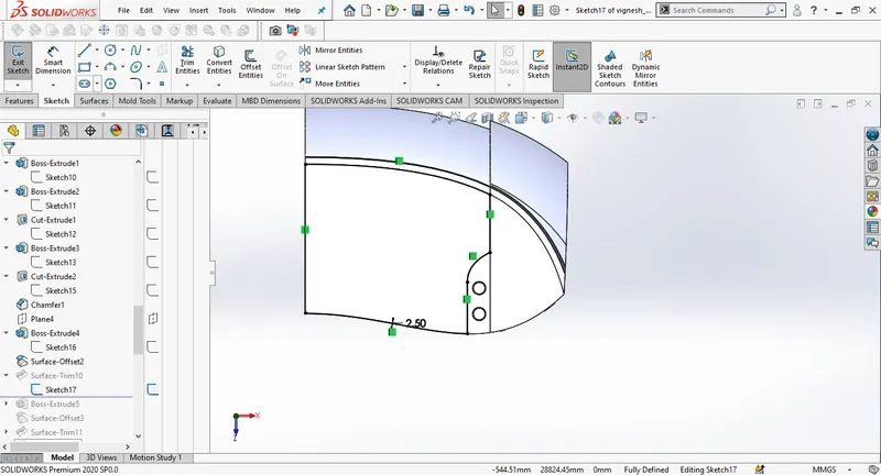
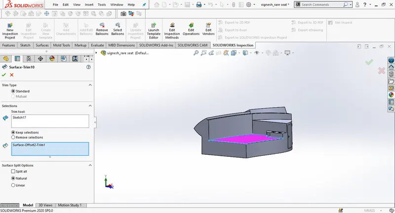
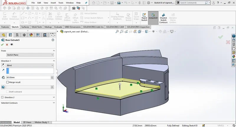
Draw a new 2D sketch on the new surface and create a boss extrude upwards to 60mm.
Create a surface offset for seat and set the offset distance to 6mm, make a 2D sketch on the new surface, use offset entities to convert the edge into sketch set the offset distance to 150mm. Then the tirm the yellow surface keeping selections. Give fillets at the required areas as per the design.
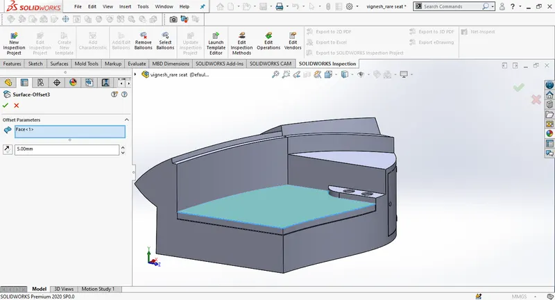
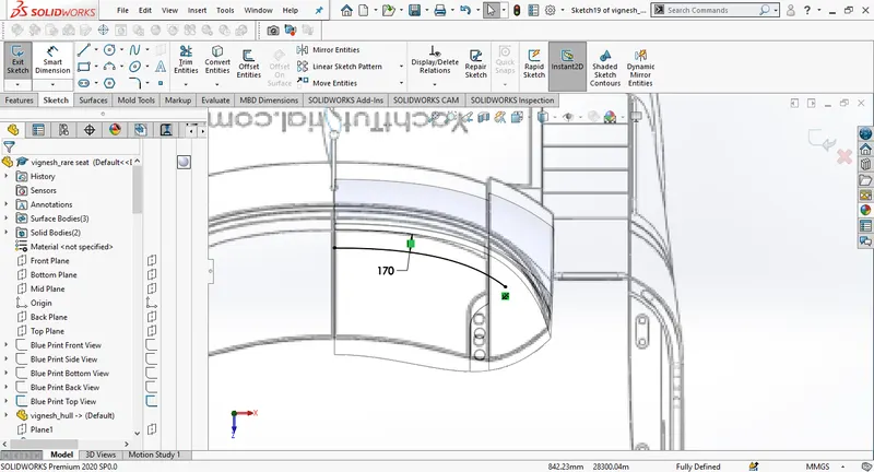
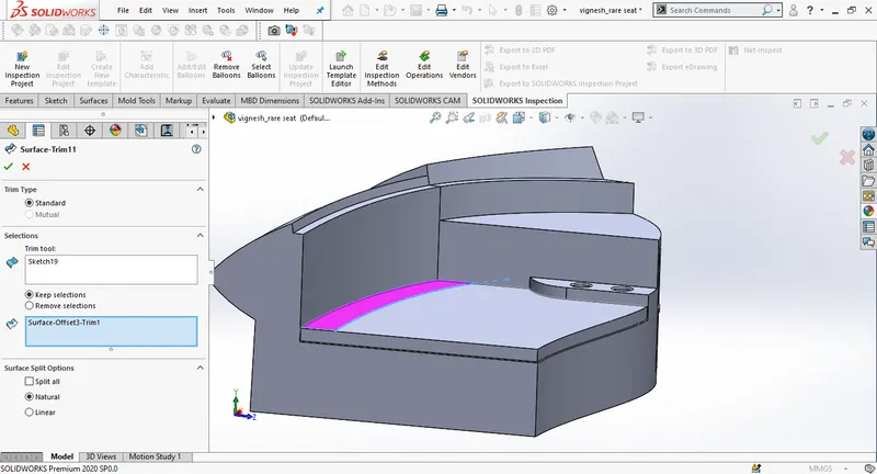
Draw a new sketch using convert entities, create an extrude boss/baseChange the distance to 300mm. Then create a chamfer, use distance-distance.
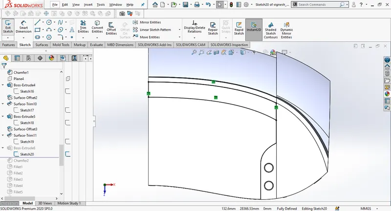
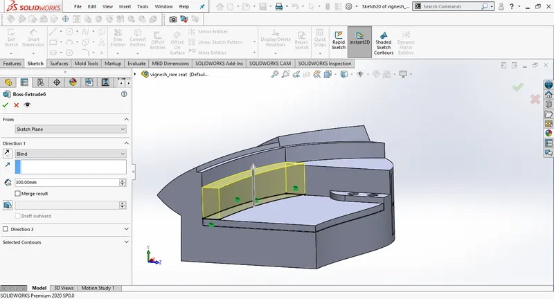
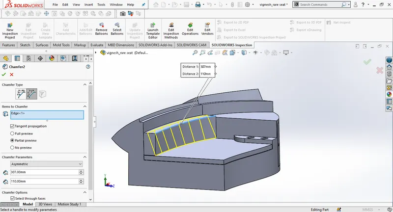

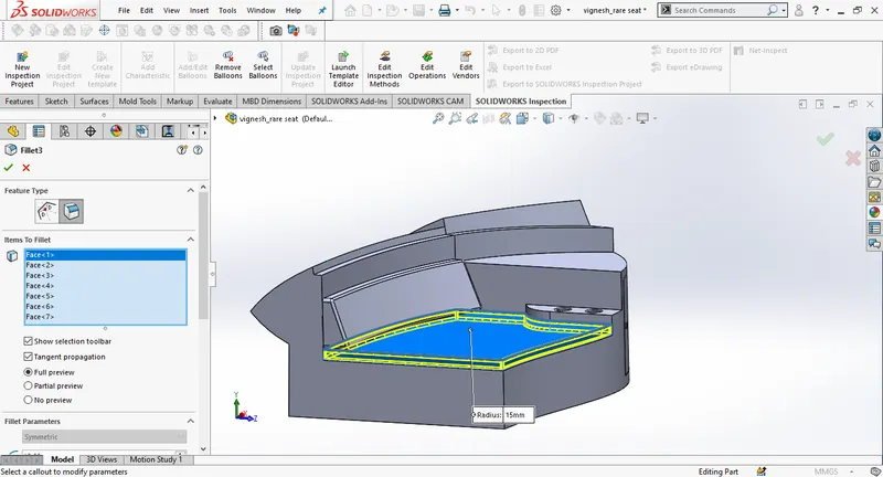
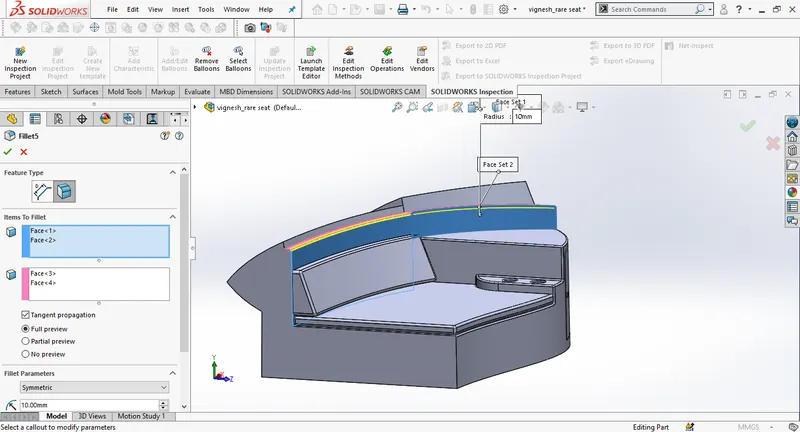
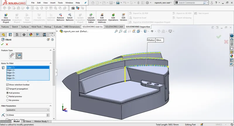
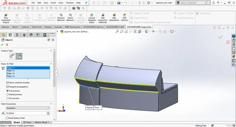
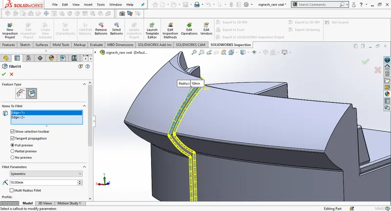
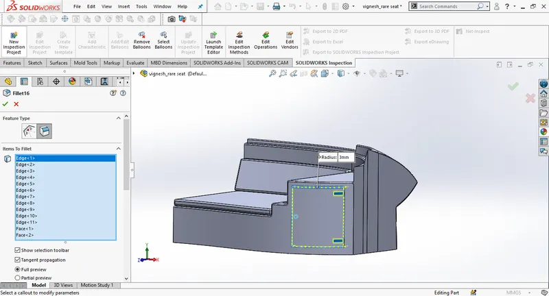
seloect plane 4 and make a 2D sketch, create an extrude and change the direction as offset from surface. Change distance to 5mm.
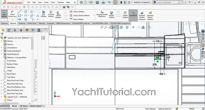
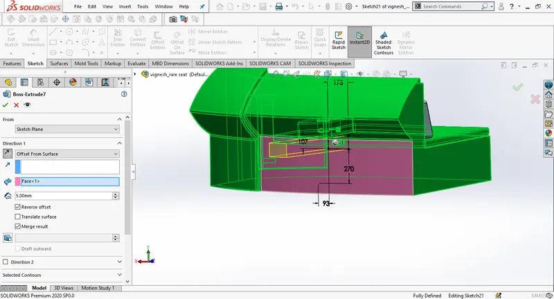
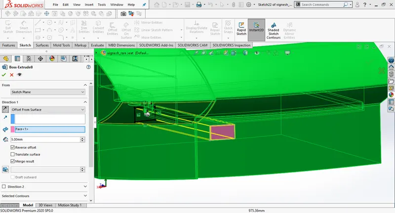
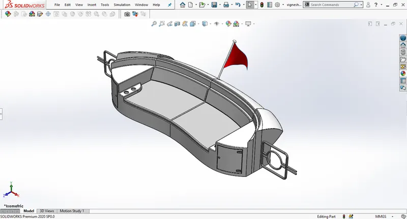
create a new sketch on the deck surface. Draw a line and make it co incident to the edge of the rear seat. Create a new plane with the sketch line as first referance and deck surface as second referance and draw a new sketch on the new plane. Again create a new plane as in the picture and create a new sketch on the plane, draw a circle of radius 20mm. Then use solid swep.
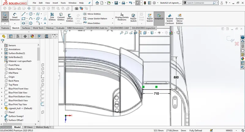
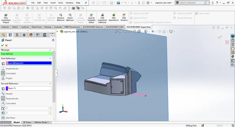

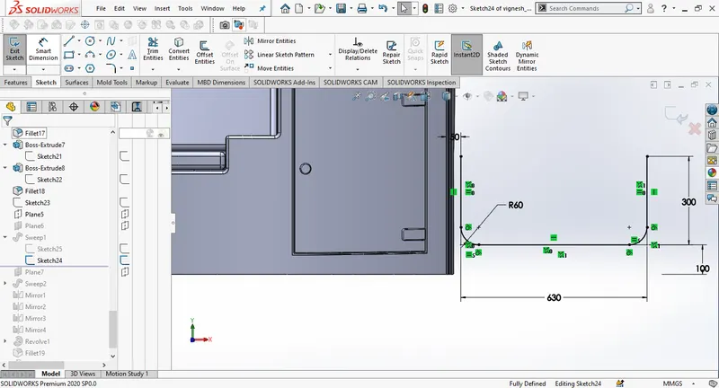
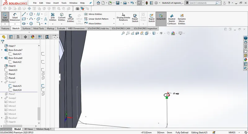
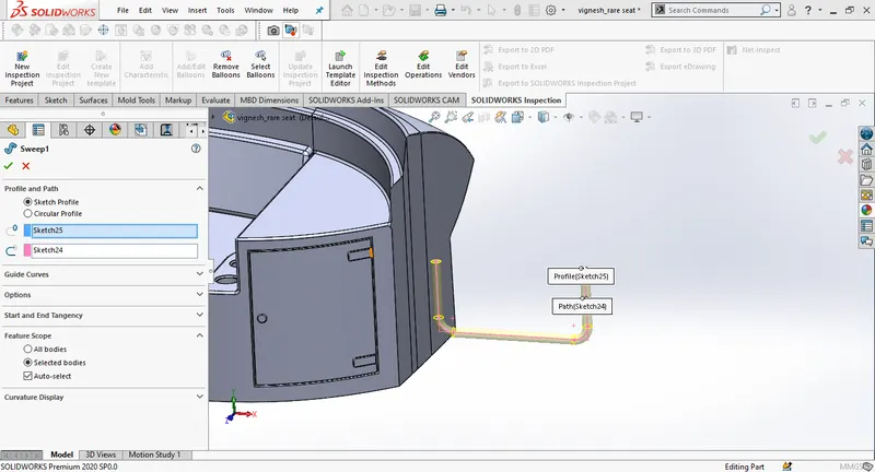
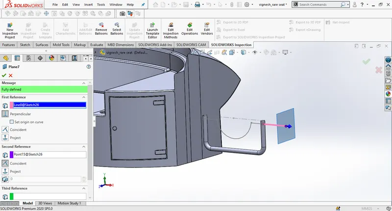
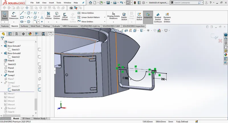
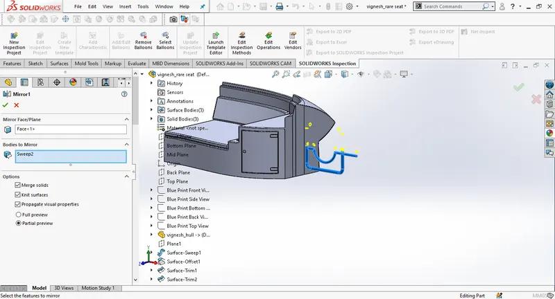
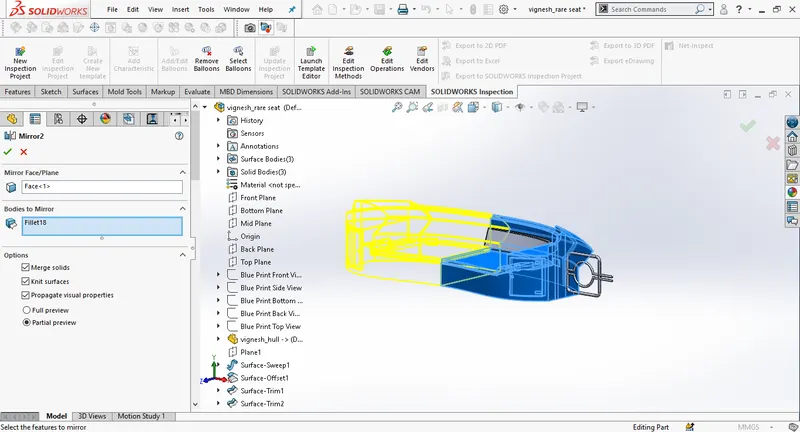
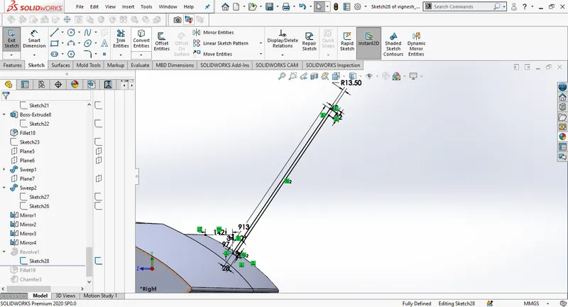
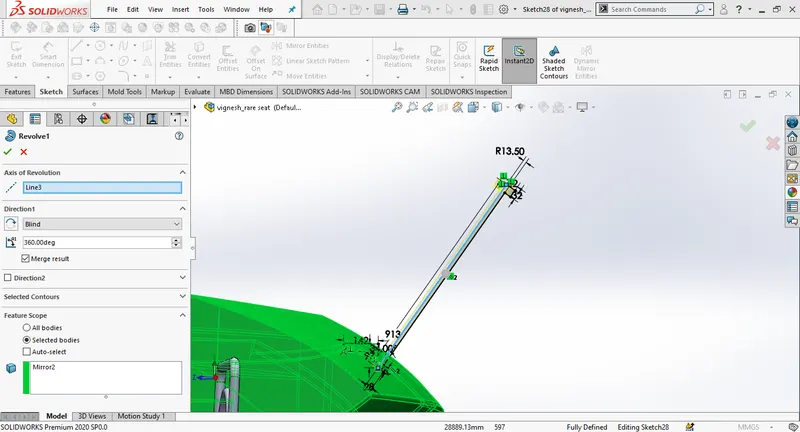
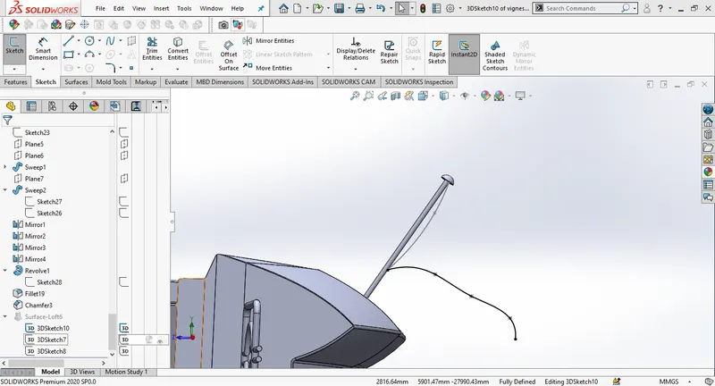
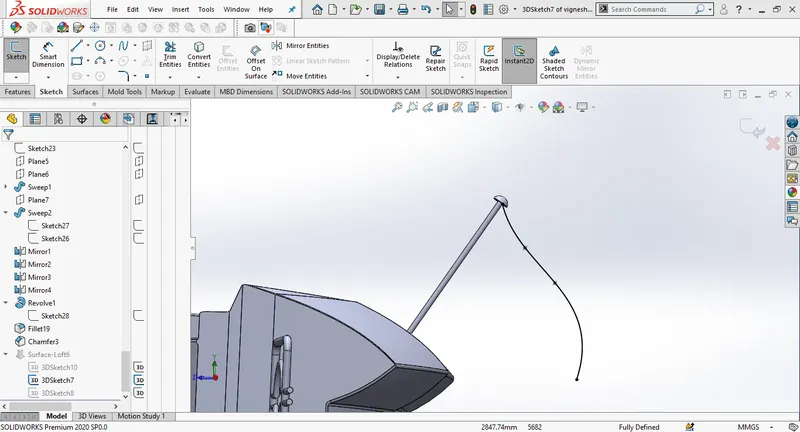
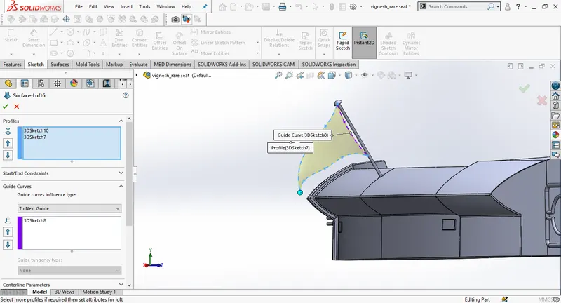
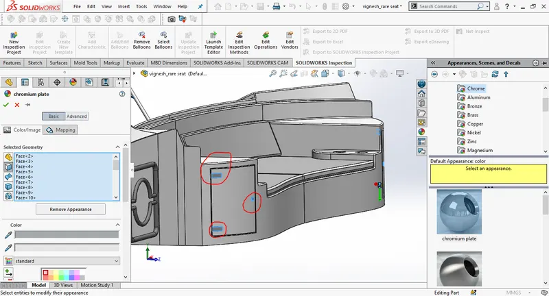
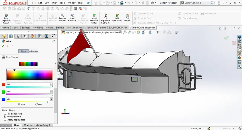
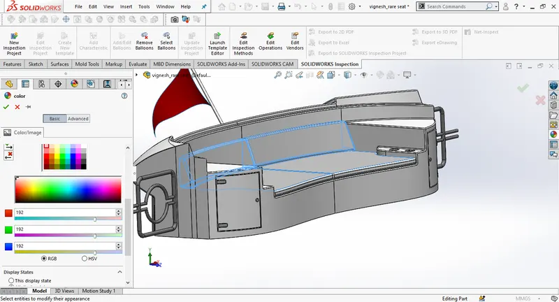
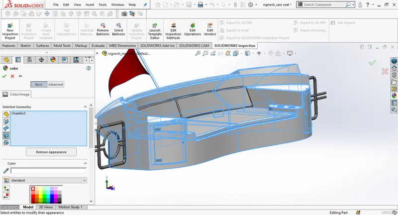
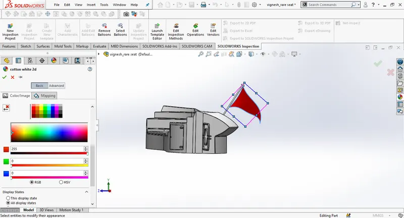
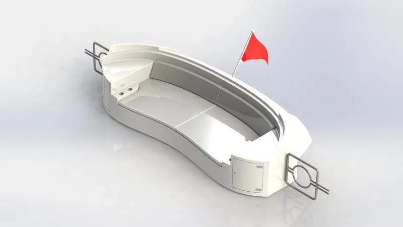
Draw a new sketch on plane 5. Use centerline and make it coincident with the solid sweep. Using midpoint of centerline draw a circle using 380mm dia. Trim the circle. Create a new plane using the recent sketch. Draw a new sketch on the new plane , draw a circle of diameter 40mm. Use solid sweep, select the circle as profile and the sketch as path. Mirror the side part and the rear seat. Draw a 3D sketch and use surface sweep to design the flag.Add appearances to finish.
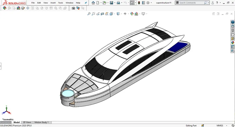
SUPERSTRUCTURE:
At first create the external surfaces and then concert it into solid part.
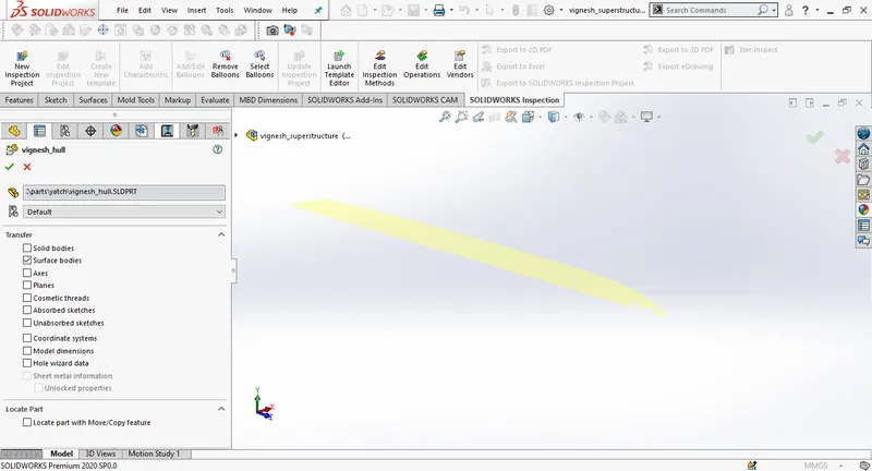
Open the blue print setup, and savet it as superstructure, then import the deck surface as done earlier. Then create a new sketch on the deck surface, take use of blurprint top view and try
to make sketch exactly close to the blueprint.
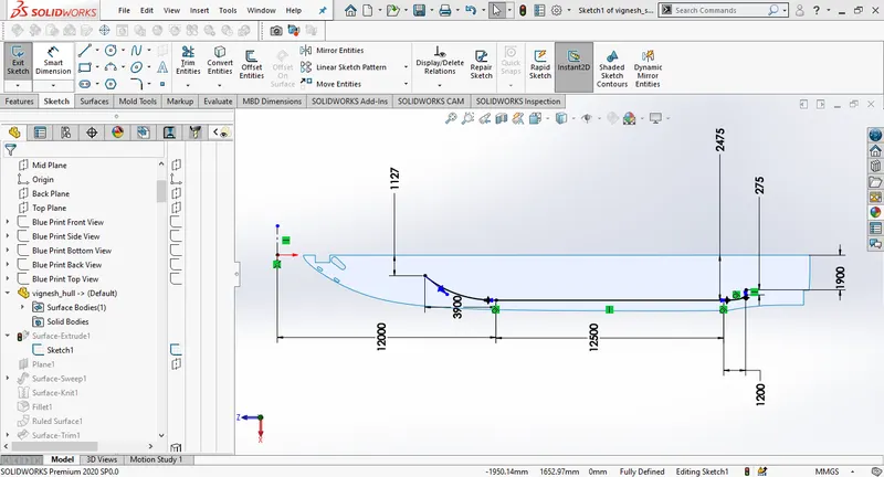
Create a surface extrude and change the distance to 600mm. Then create a new plane and draw a new sketch on the new plane.
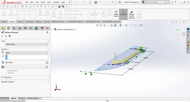
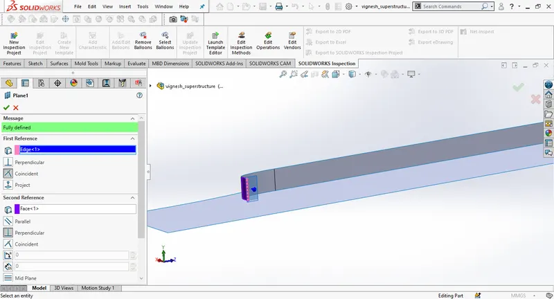
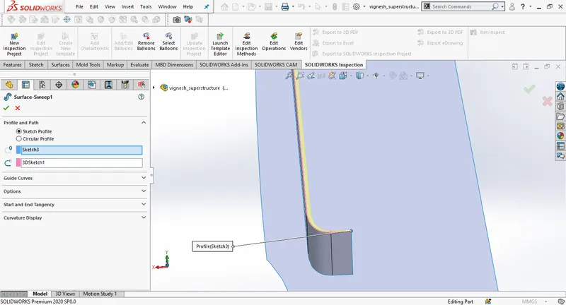
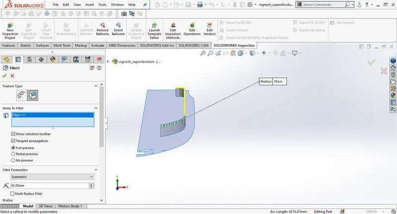
Draw a 3d sketch use convert entities to make the sketch, using both the sketches use surface sweep, Knit the surfaces together, and then add fillet.
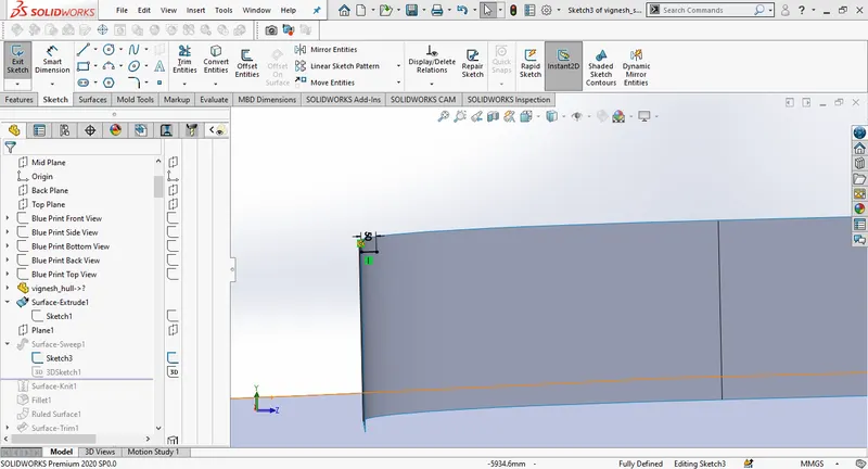
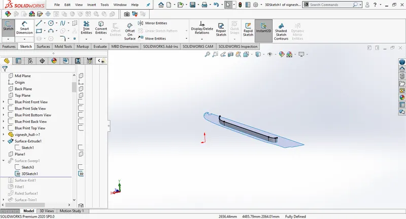
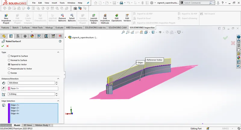
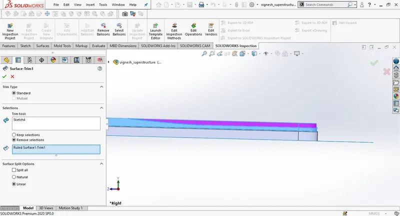
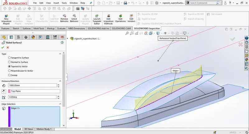
Create a ruled surface by nselecting the inner edge, enable the taper to the vector option and give the distance as 500mm. Create a new sketch on the midplane, using surface trim, remove the upper surface.
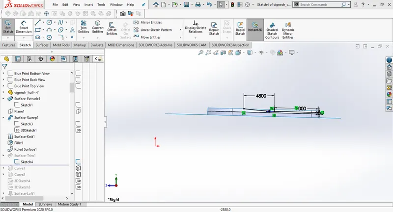
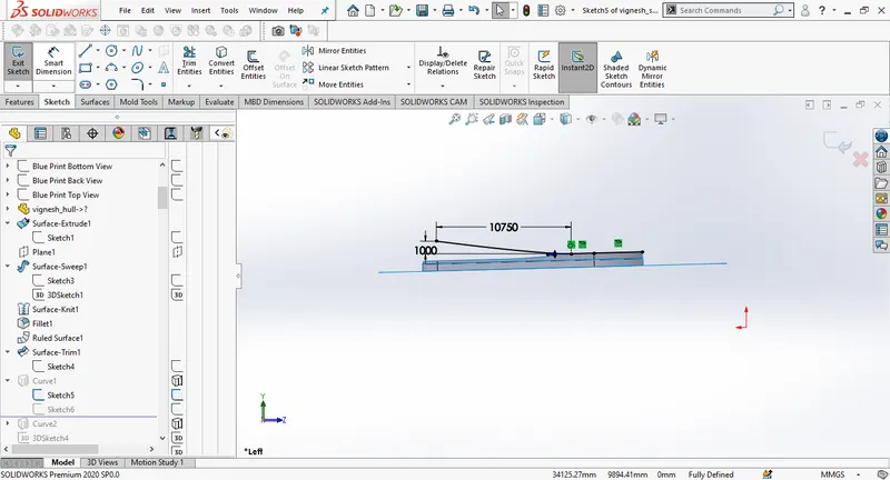
Create a new sketch on the midplane and then on the top plane using both the sketches project the curves.
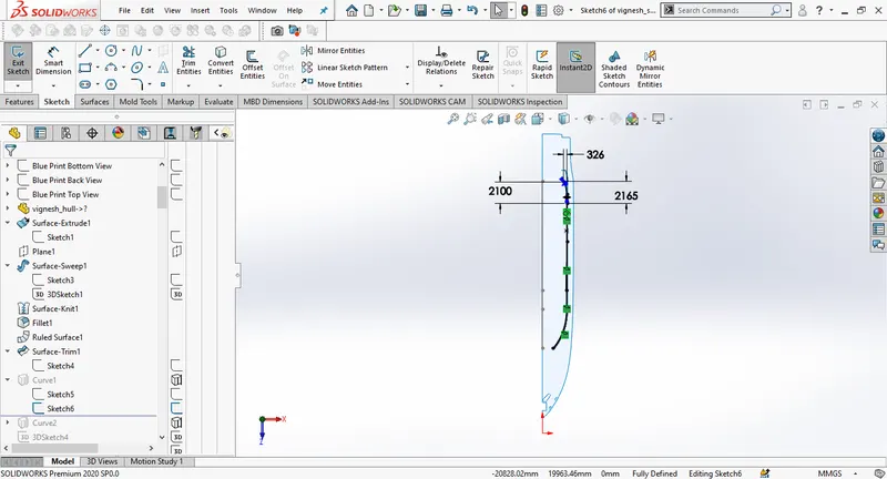
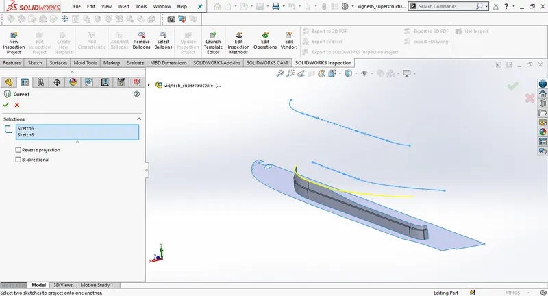
Create another curve in the same manner.
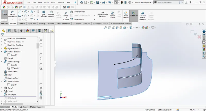
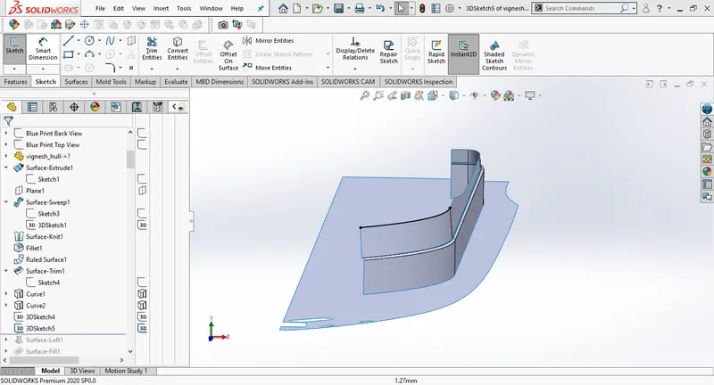
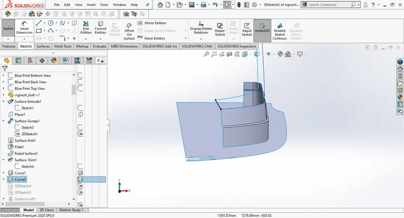
Then create a surface loft using both the curves.
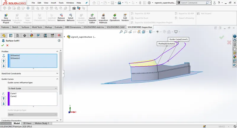
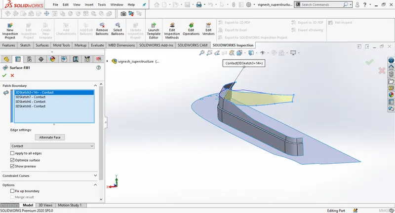
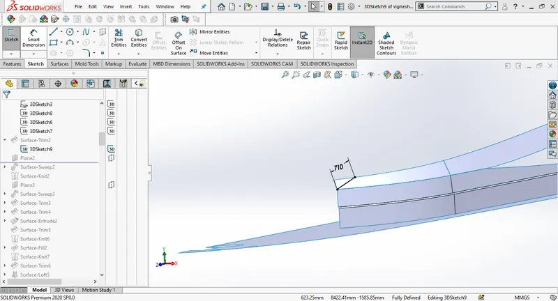
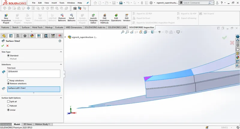
Create a new plane, draw a new sketch on the new plane and then create a surface sweep. Then knit the surfaces together.
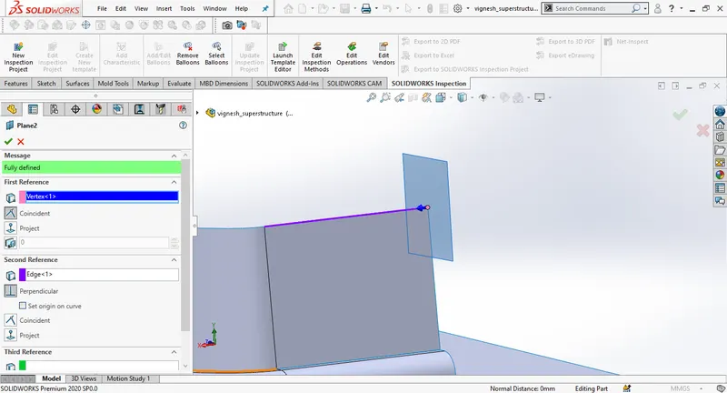
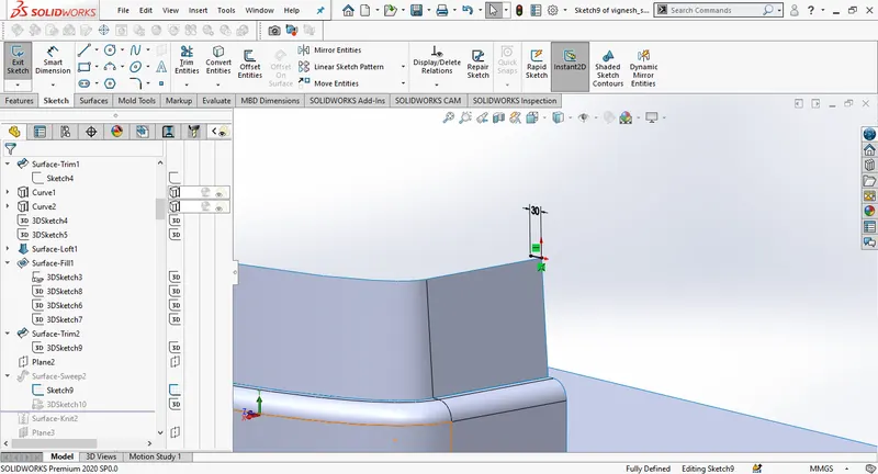
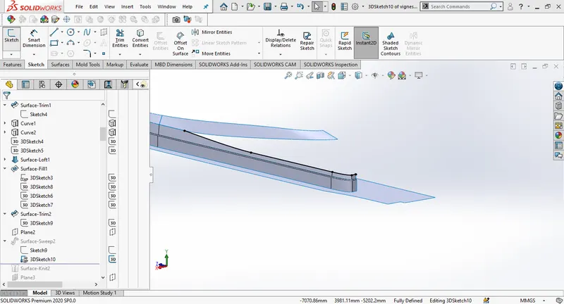
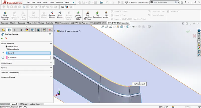
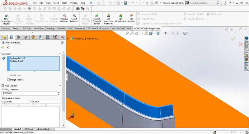
Create a new plane and then draw a new sketch on the new plane and then create a surface sweep, using surface trim, trim the extra edges.
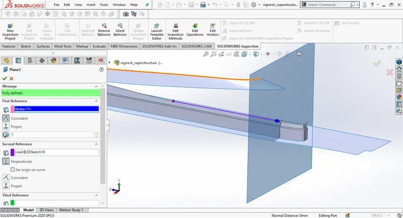
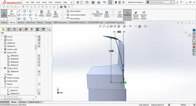
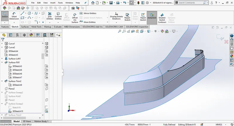
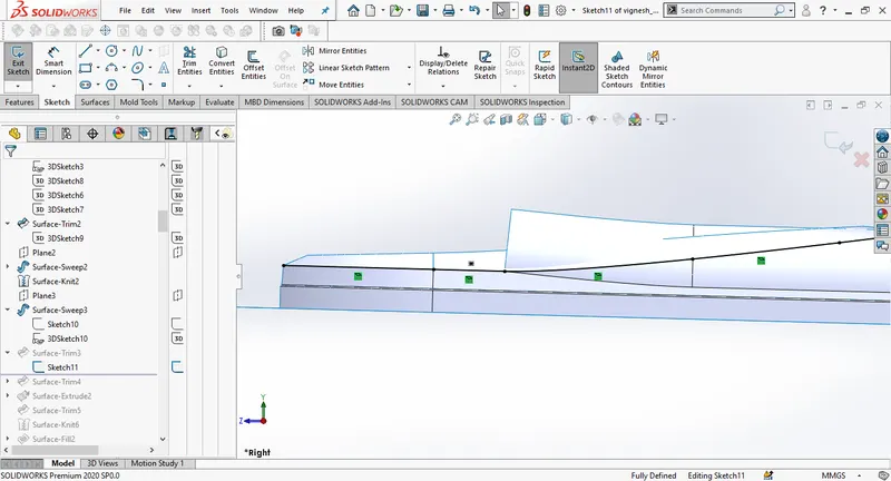
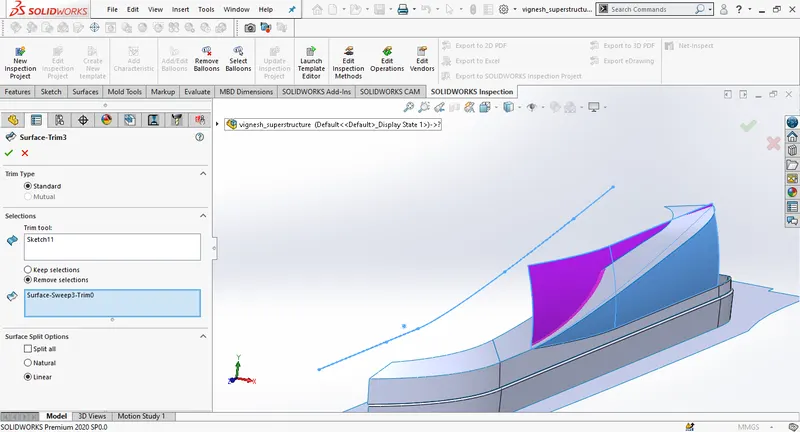
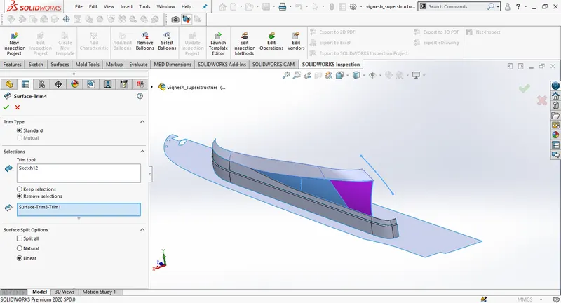
Create a new plane on the mid plane and then create the surface extrude.Change the distance to 3000mm. Change the direction to front side. Then using surface trim, remove the intersecting edges. Then use surface knit.
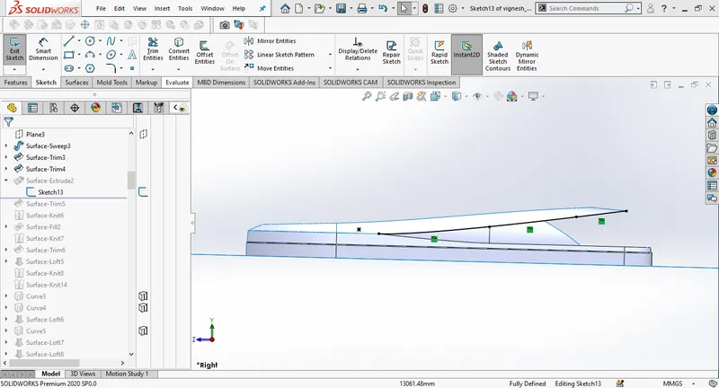
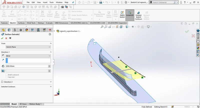
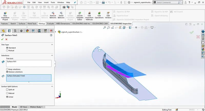
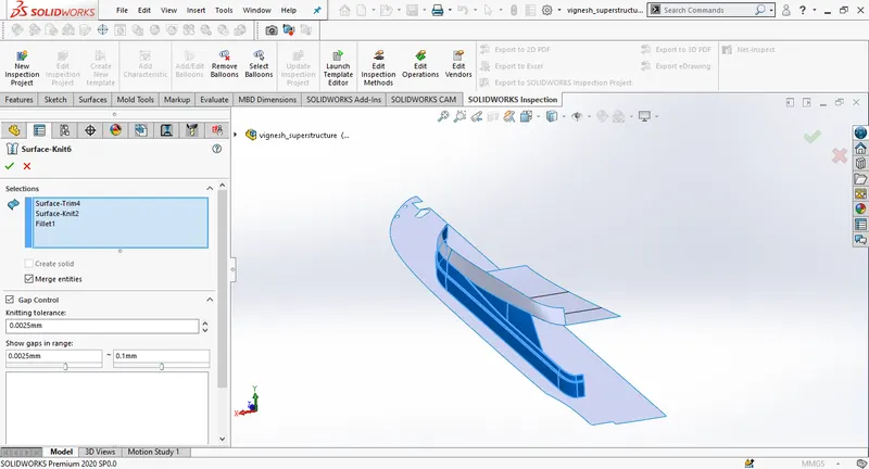
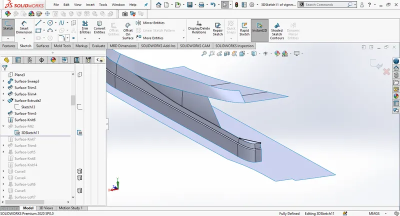
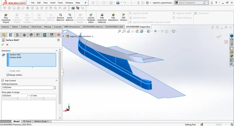
Draw a 3D sketch then connect the endpoints to the superstructure. Fill the sketch using surface fill. Knit the surfaces. Draw a new sketch on the recent surface, draw a spline, and give horizontal and tangent relations. trim the outer surface enabling remove material.
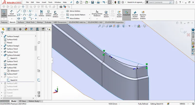
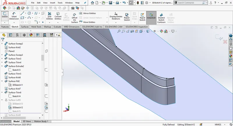
Draw a 3D sketch using convert entities , draw another sketch on the plane 2. Create a surface loft using both the sketches as referance. Knit the surfaces.

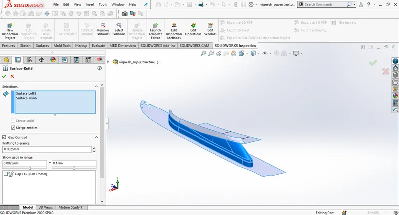
Create a new sketch on the midplane taking help of blueprint sideview. Draw a spline fix the endpoints to the superstructure. Draw a new sketch on the top plane, use convert entities and select the edge of the superstructure, create a projected curve using bothe the sketches.
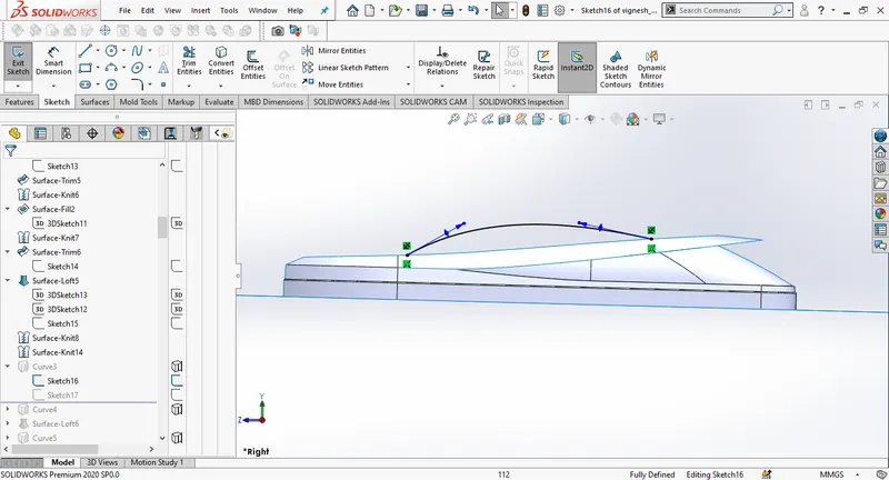
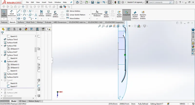
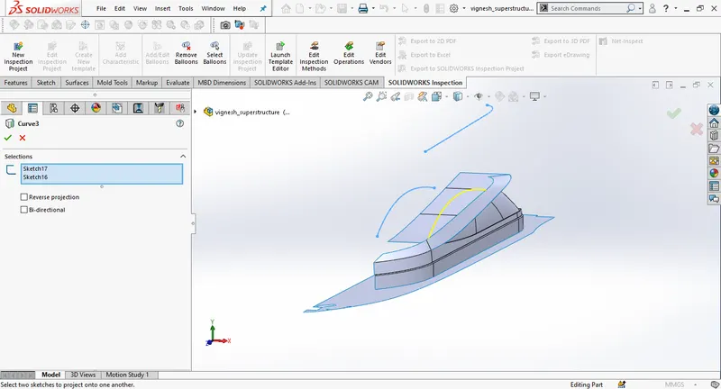
Create a new sketch on the midplane, another sketch on the top plane, create a projected cure using the sketches.
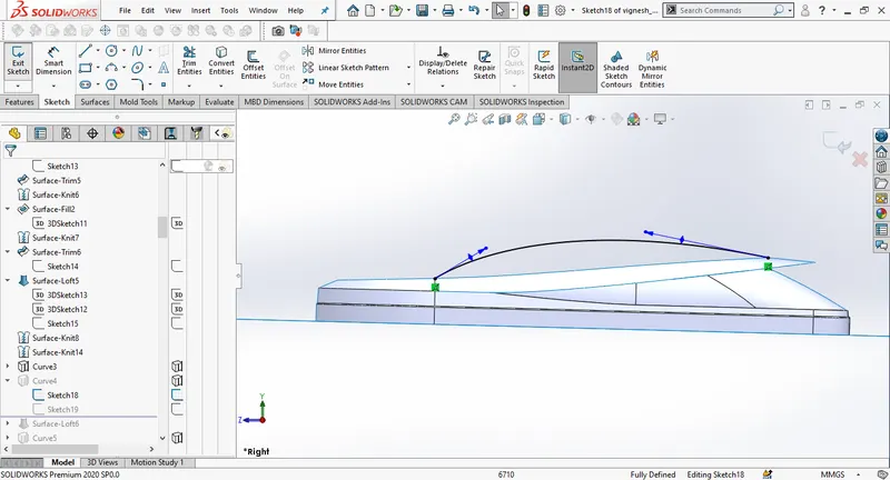
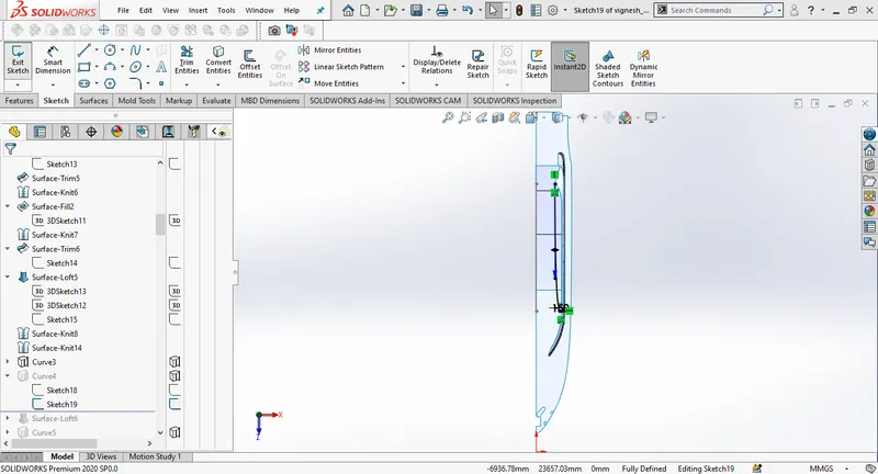
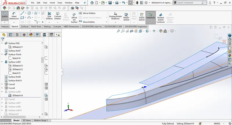
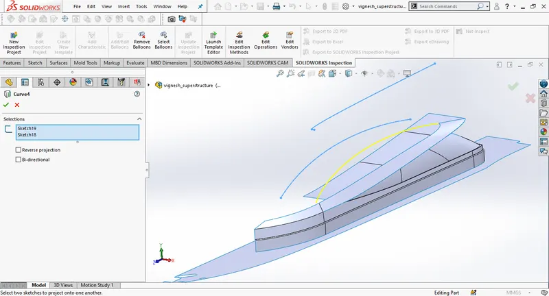
Create a surface loft using both the curves
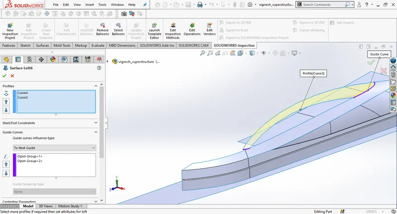
Draw a new sketch on the top plane off set the edge of the surface loft, set the offset distance to 220mm. Create a new sketch on the midplane, then use projected curve. Create a 3D sketch, select the edge of the surface loft and use convert entities. Then create a surface loft.
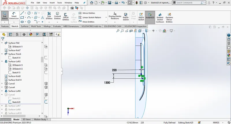
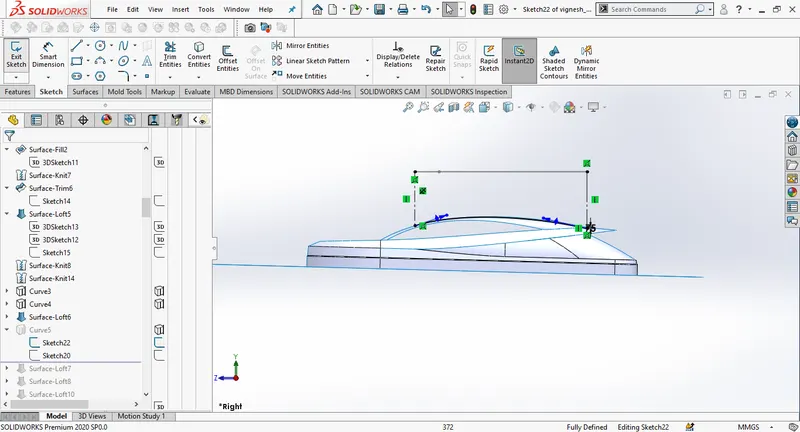
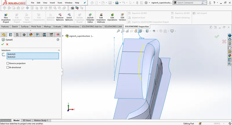
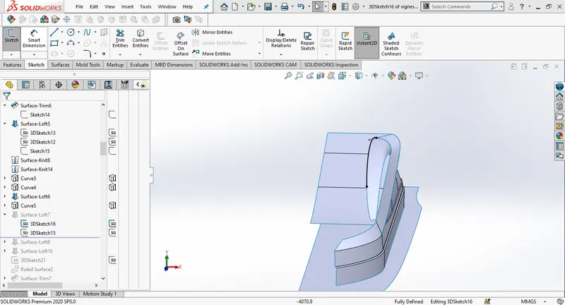
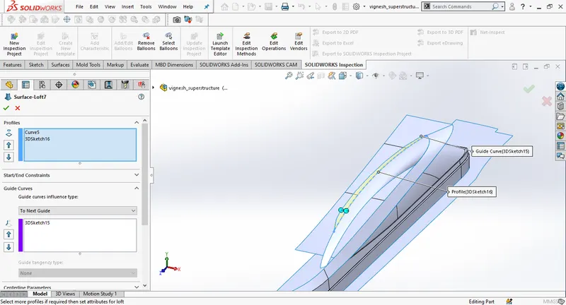
Draw a spline on the midplane and adjust the spline handels close to the blueprint ,then 3D sketches respectively as shown in pictures. Then create a surface loft.
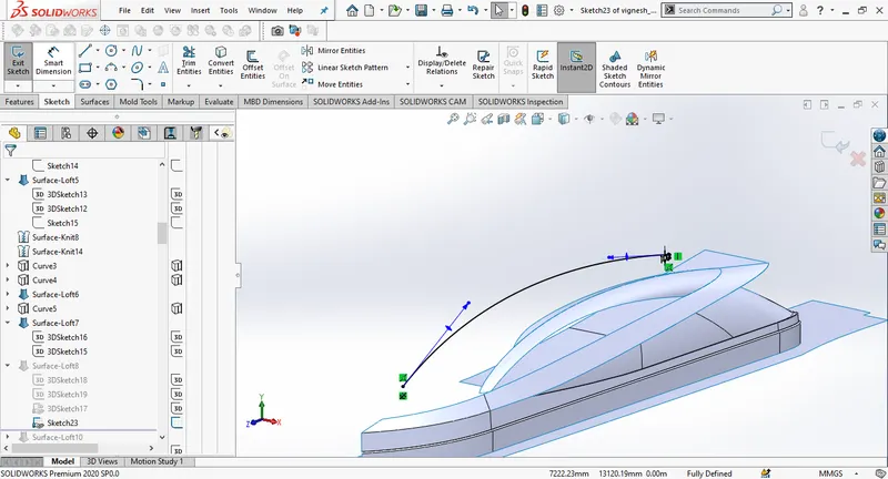
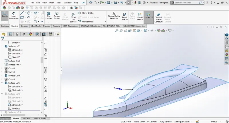
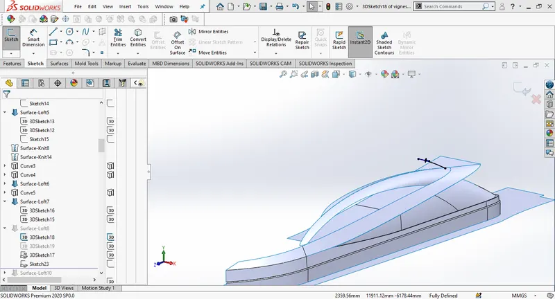
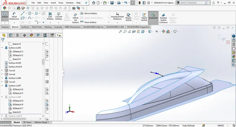
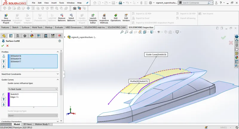
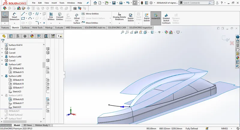
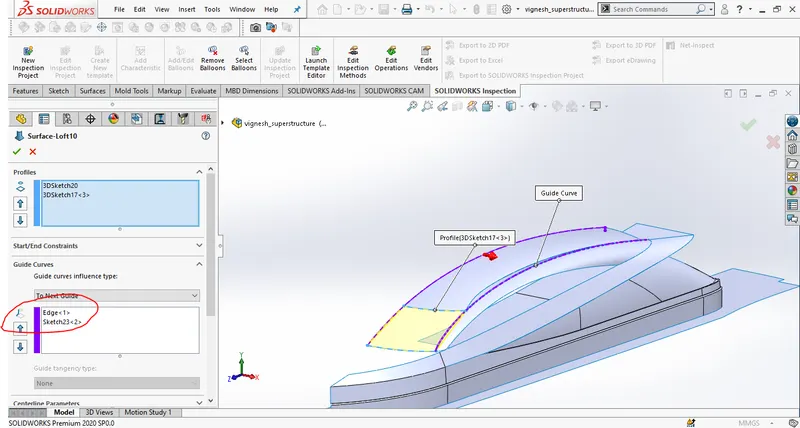
Create a 3D sketch, select the edge of the surface extrude and then convert entities, create a ruled surface. Draw a new sketch on the midplane, Draw a spline and make it close to the blueprint. Trim surfaces to remove extra material.Knit the surfaces in the end.
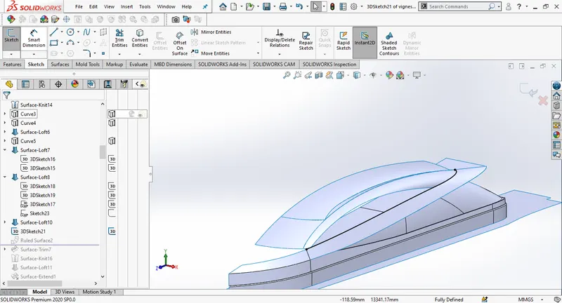
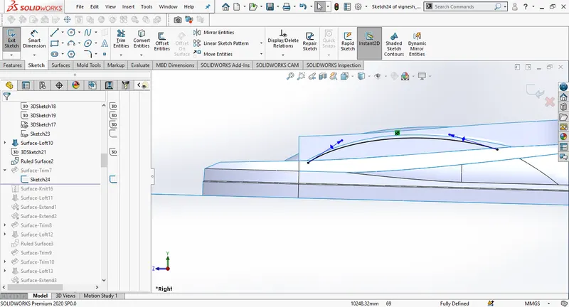
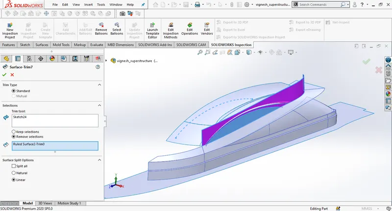
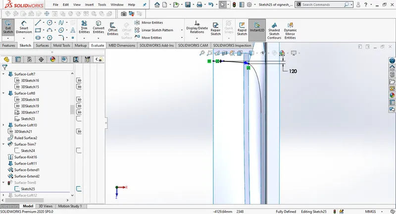
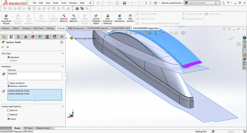
Extend the surfaces and then create a new sketch on the top plane. using surface trim remove the unwanted surfaces.
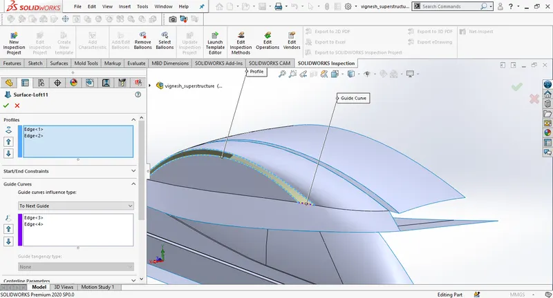
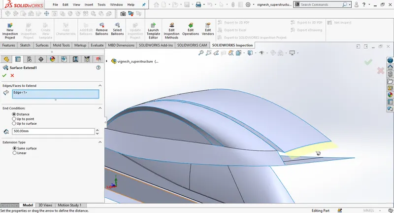
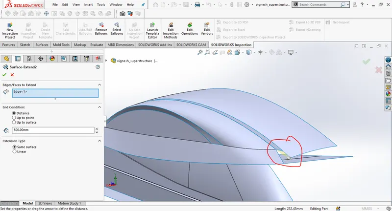
Draw a 3D sketch and create surface loft to fill the space.
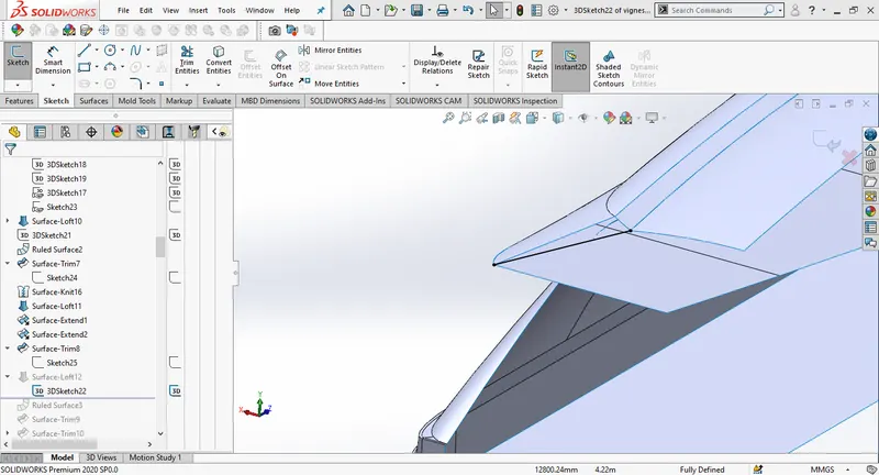
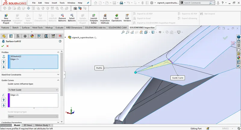
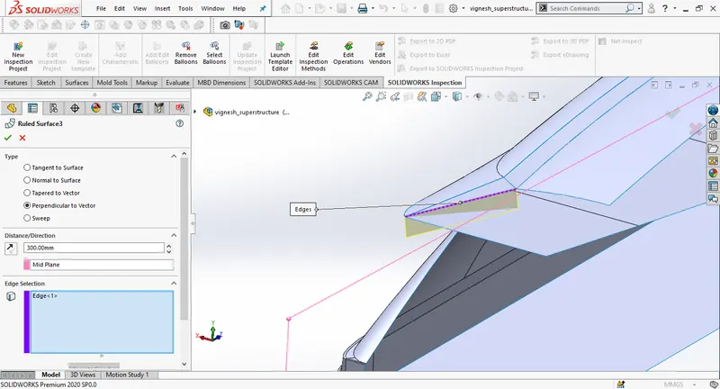
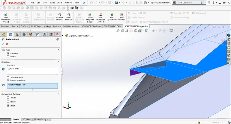
Create a ruled surface selecting the edge as shown in the picture, then remove the extra surfaces using surface trim.
Create a new sketch on the top plane Draw a spline and connet one edge of spline to the edge of the surface loft and another to the mid plane.Create a surface loft.
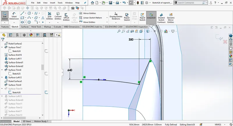
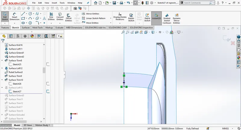
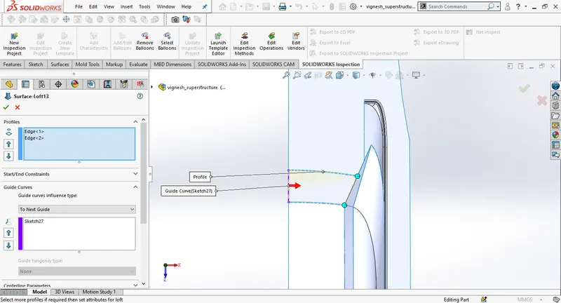
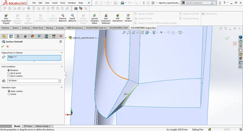
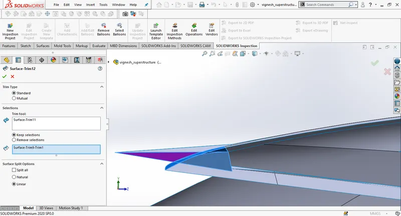
Draw a new sketch on the deck surface then create a surface extend, trim the upper surface.
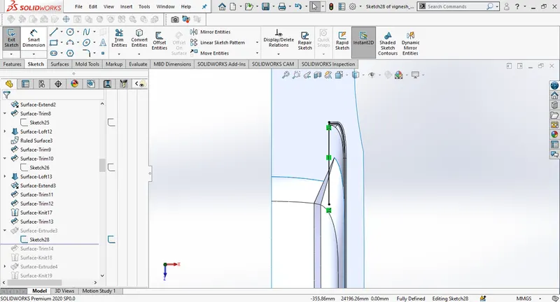
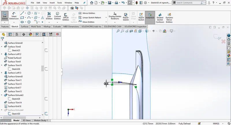
Draw another sketch on the deck surface to create the surface extrude, knit all the surfaces in the end.
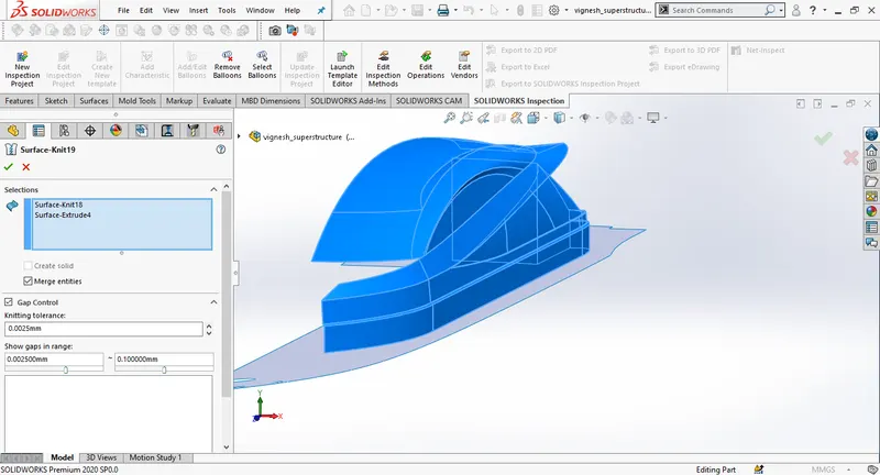
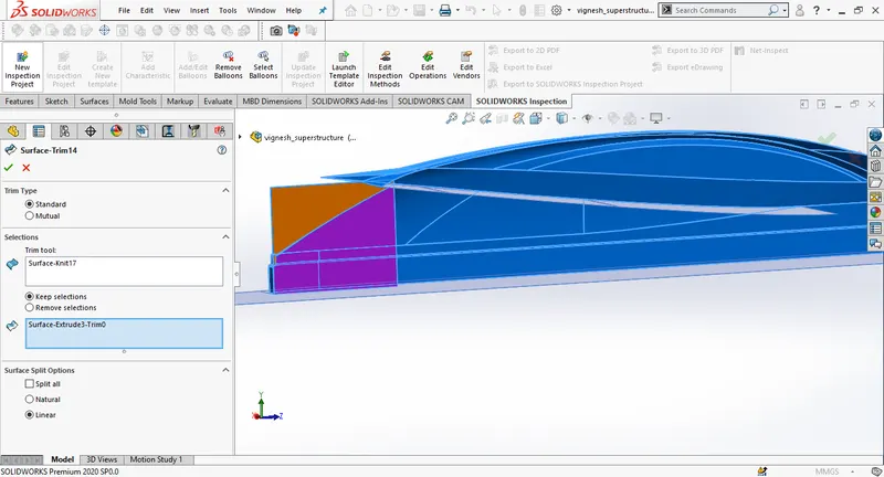
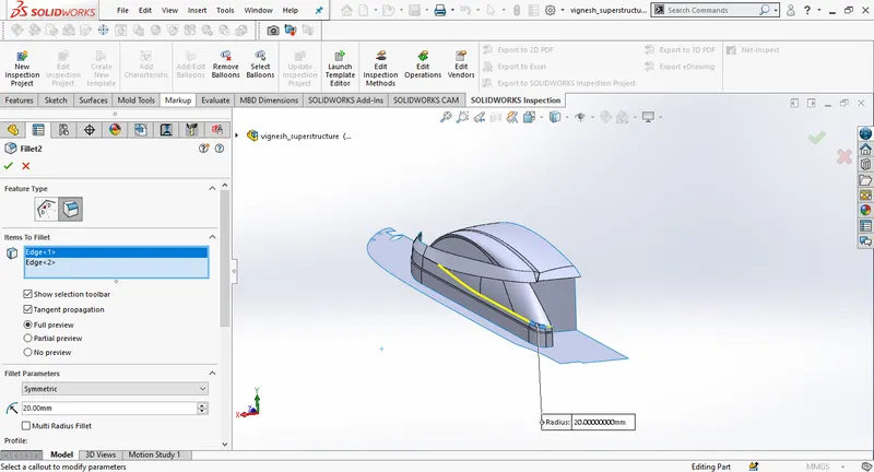
Exrend the surfaces as in the picture and remove unwanted surfaces using surface trim.
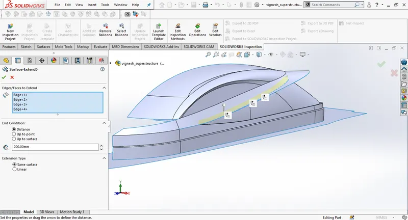
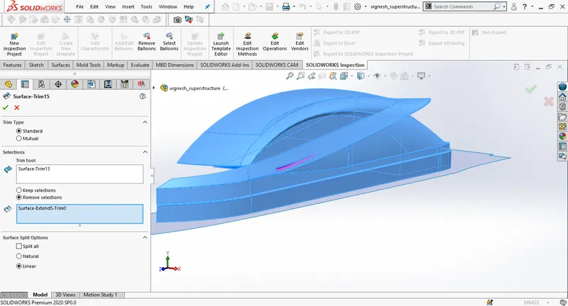
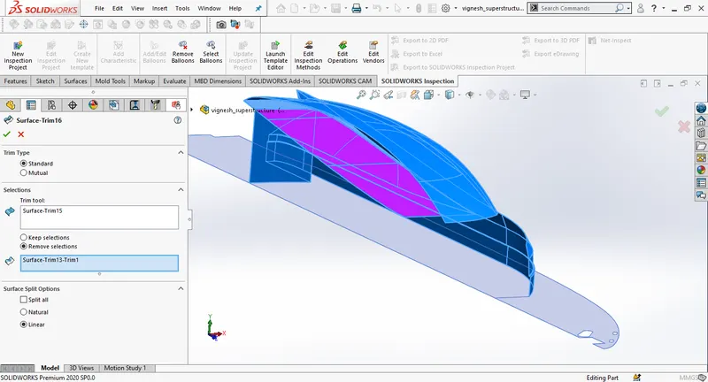
Draw a new sketch on the midplane a create a surface extrude.
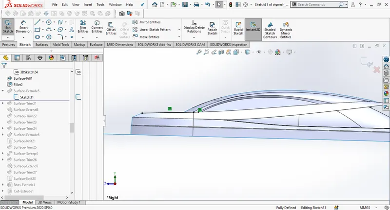
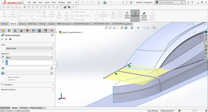
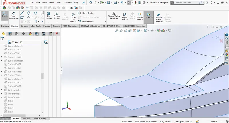
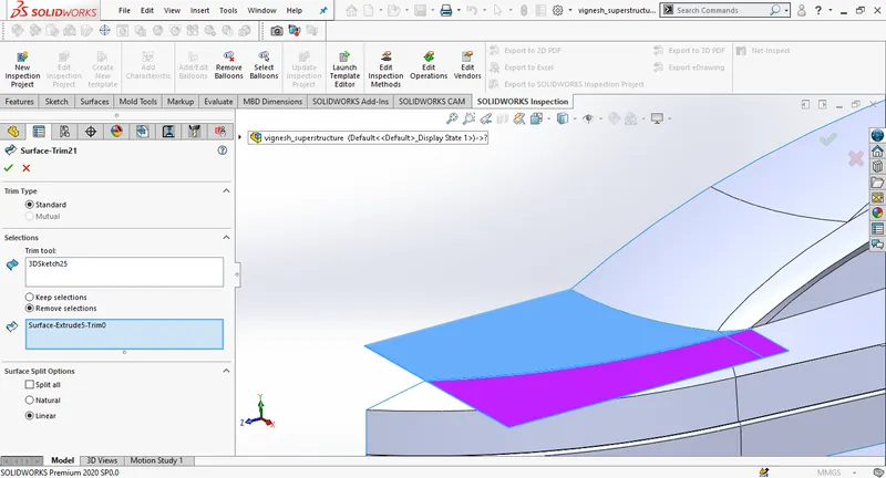
Extend surface and trim using surface trim.
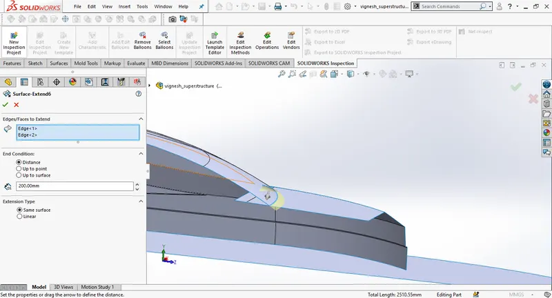
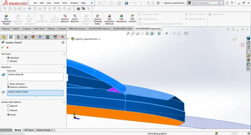
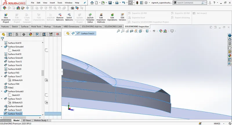
Draw a new sketch on the top plane and trim the inner surface, then create a new sketch on the deck surface and then extrude the surface. Trim the upper edge and knit the surfaces.

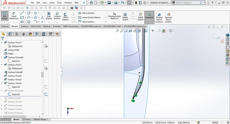
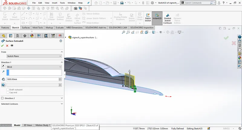
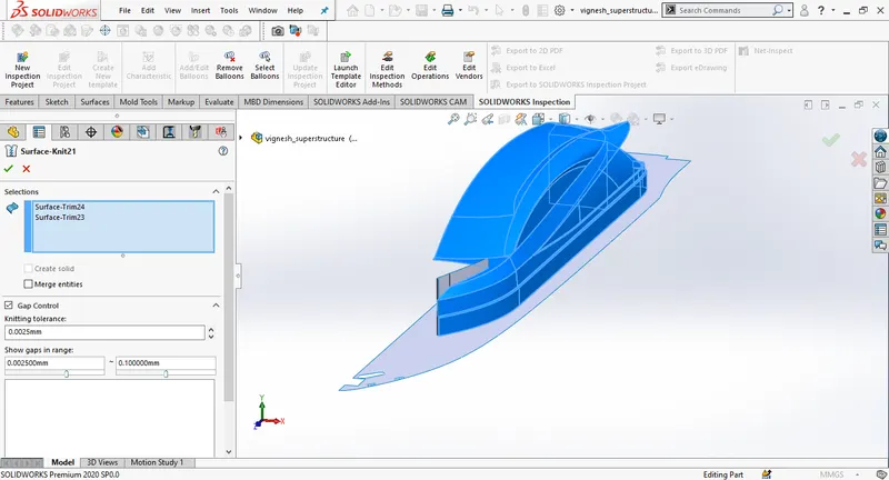
Draw a new sketch on the mid plane then create a surface sweep.
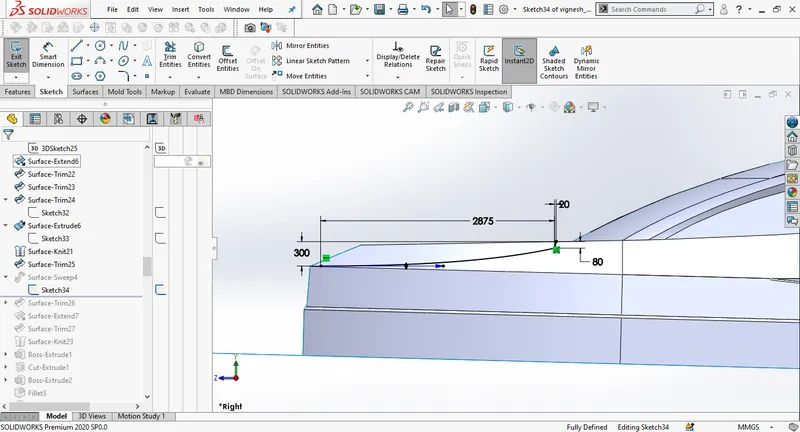
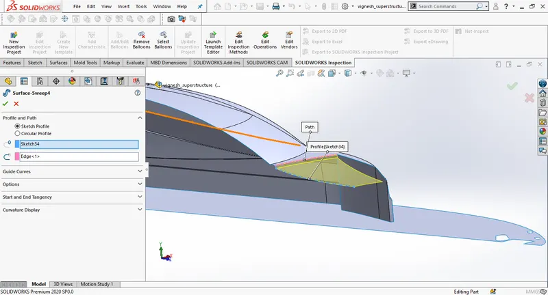
Draw a straight line on the top plane and using the sketch trim the front surface.
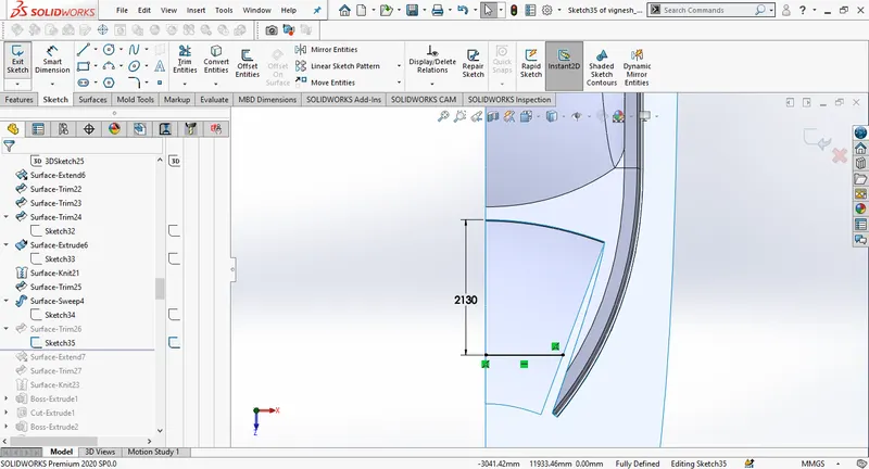
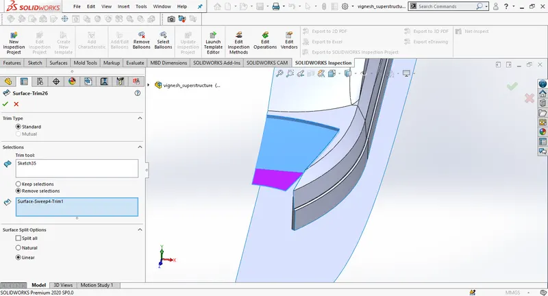
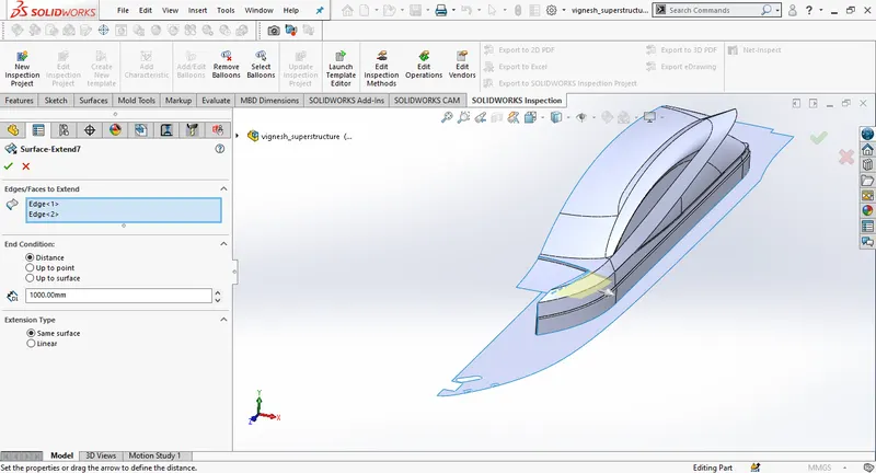
Extend the surface and trim the outer surface knit the surfaces.
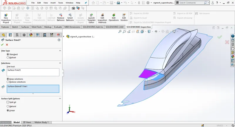
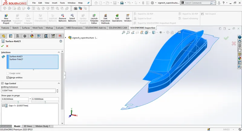
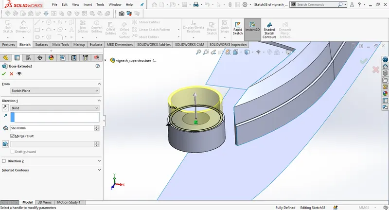
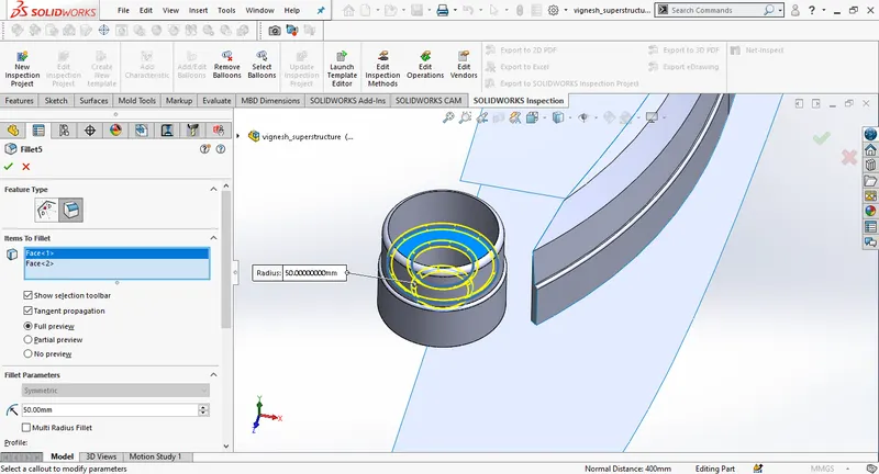
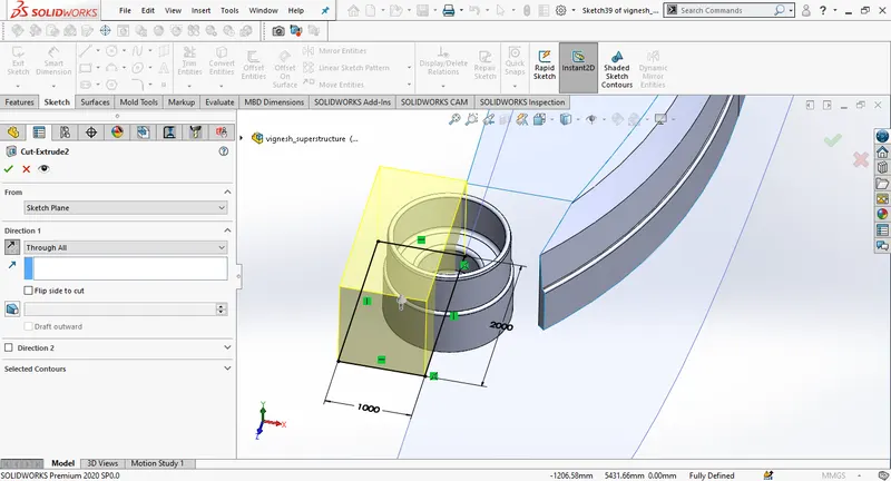
Draw a ciecle on the deck surface, draw a circle and use extrude boss. change the distance to 600mm towards upwards. Then create an extrude cut with circle of diameter 700 and depth 400mm.
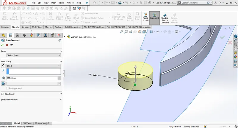
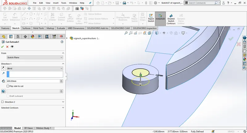
Draw another circle above the extrude boss and then extrude the sketch.
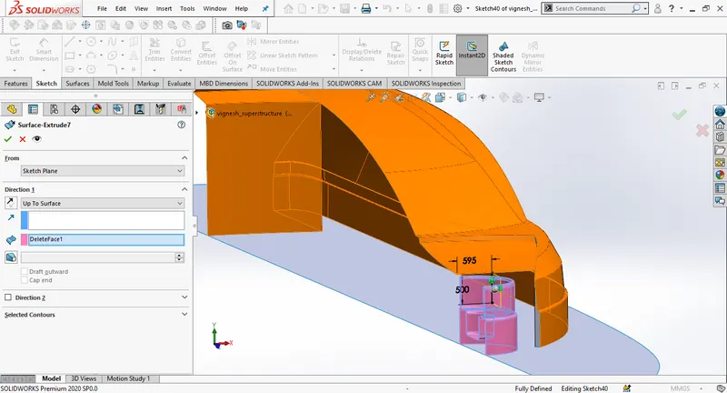
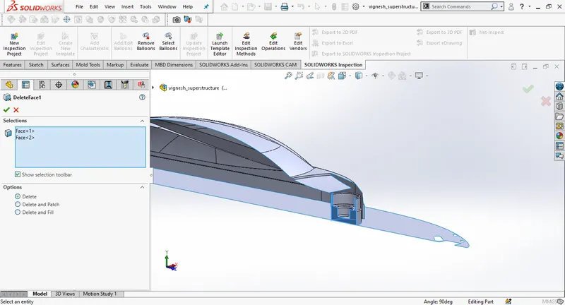
Create a new plane, create a new sketch on the new plane and then use surface extrude, select direction as upto surface. Then create a new sketch on the recent surace extrude, then create a surface extrude. Extend the edge at the top stair and then use surface trim to remove surface.
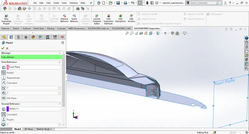
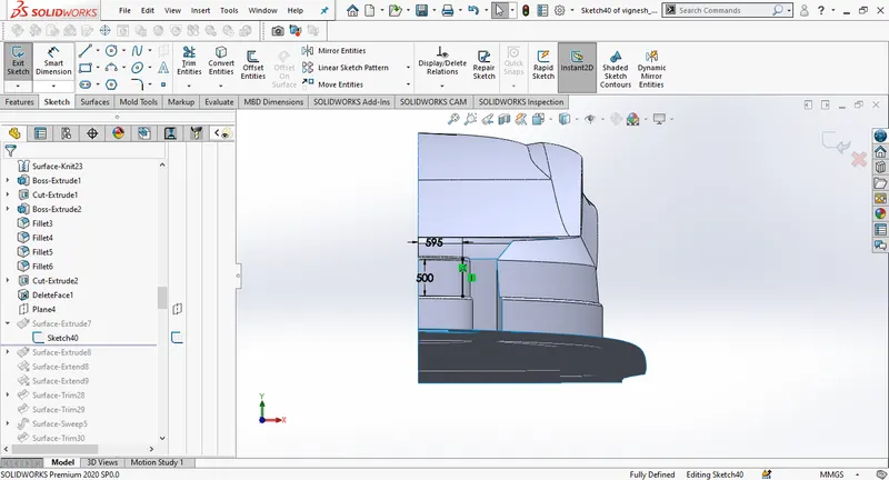
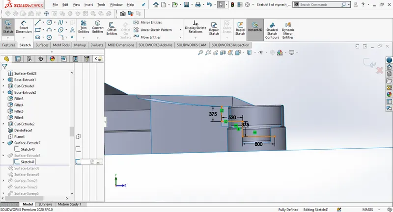
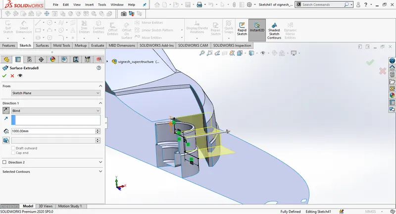
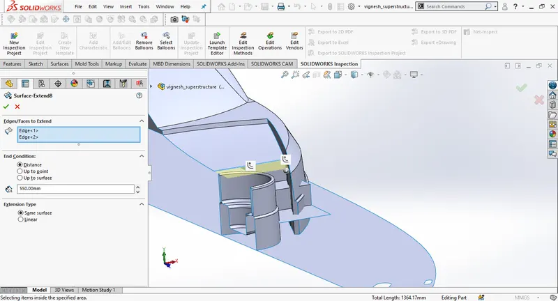
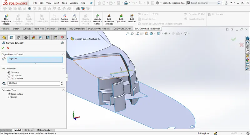
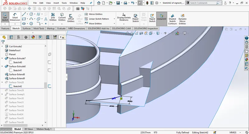
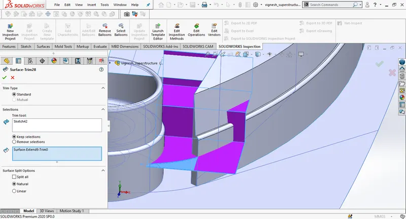
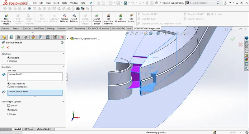
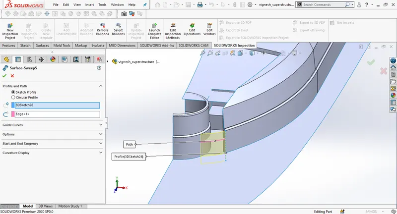
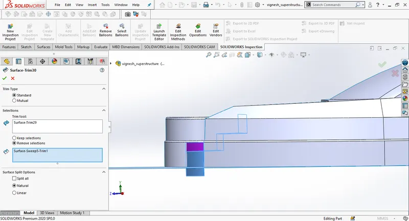
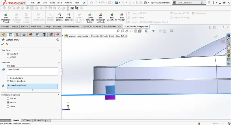
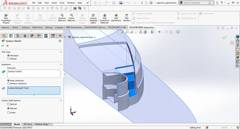
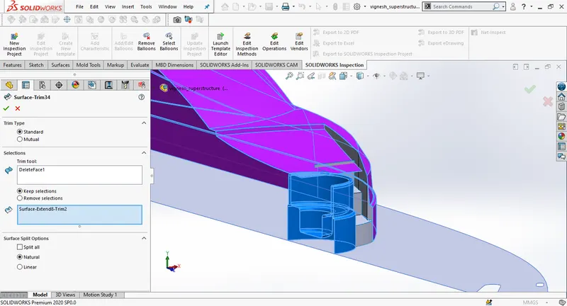
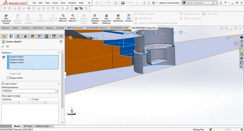
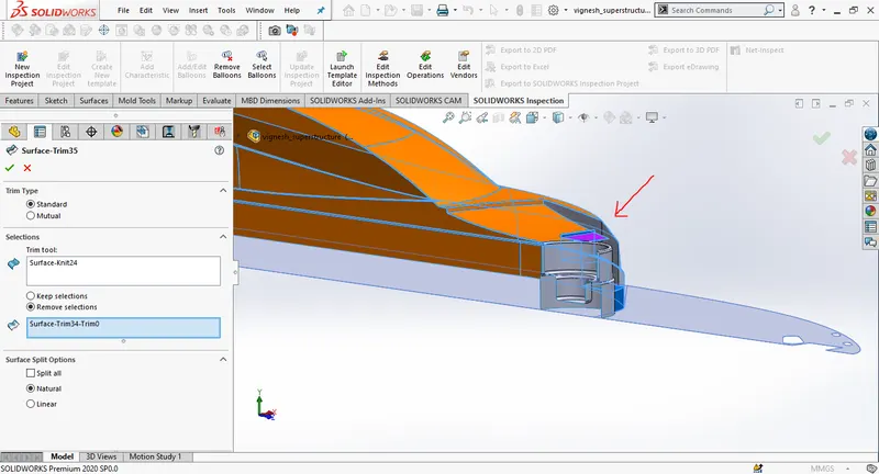
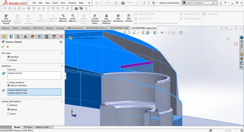
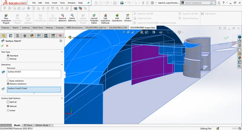
Knit the surfaces, then trim the inner part of the pool area. then trim the deck surface.
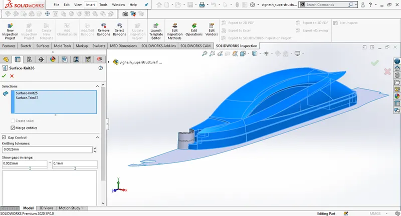
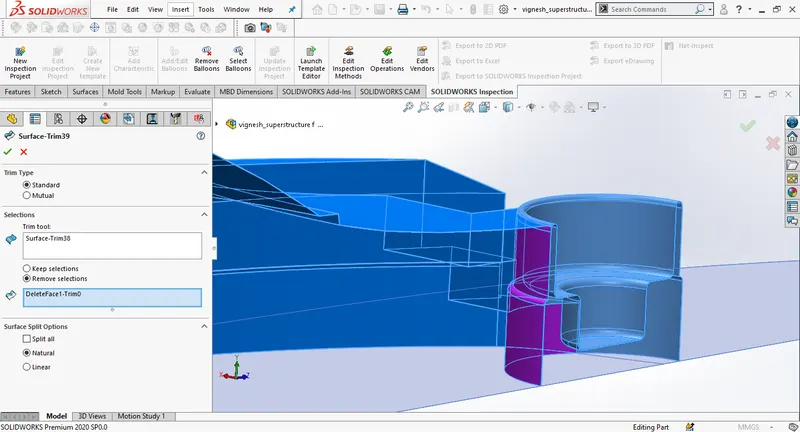
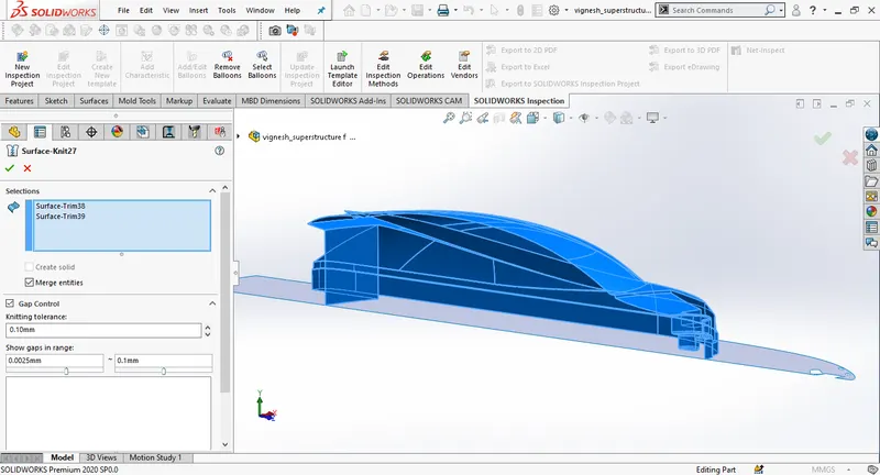
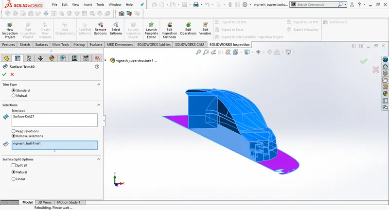
Create a new sketch on the bottom plane and use surface extrude and trim the purple part.Knit the surfaces make sure it results all black edges and enable try to form solid body.
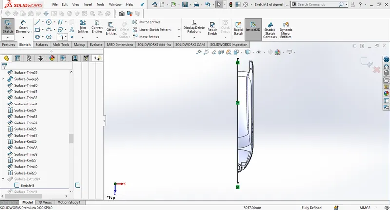
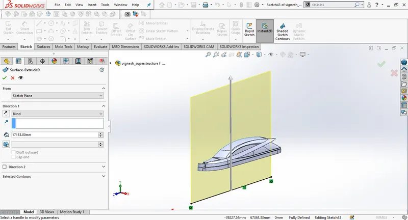 .
.
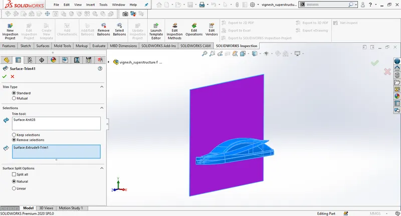
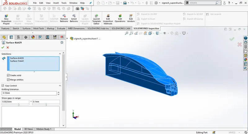
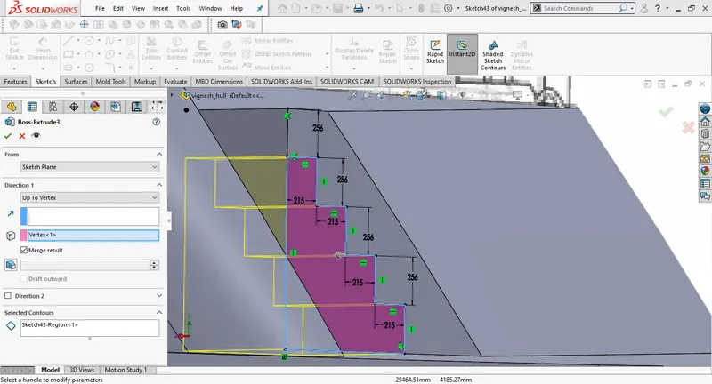
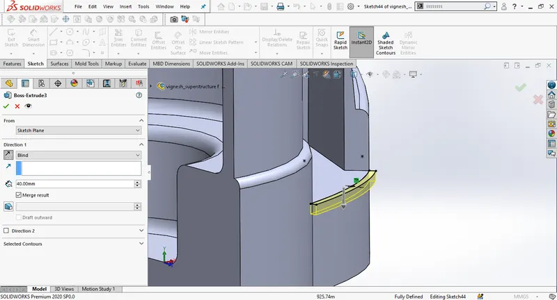
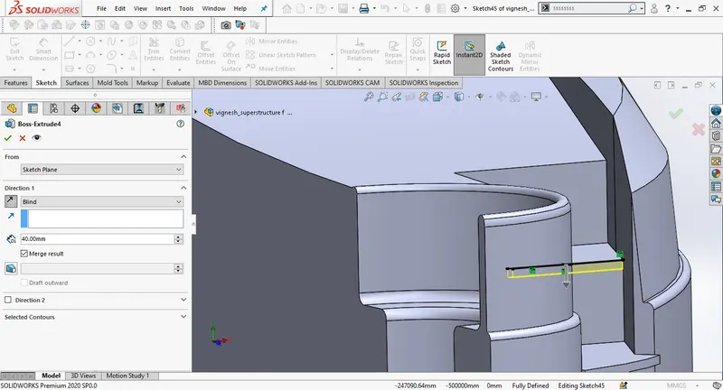
Create a new sketch on the stair surface by offsetting the edge and then use boss extrude. Repeat it for rest of the stairs.
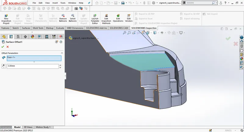
Create a surface offset for the blue surface as shown in the picture, create a new sketch on the top plane then use surface trim to use thye extra part.
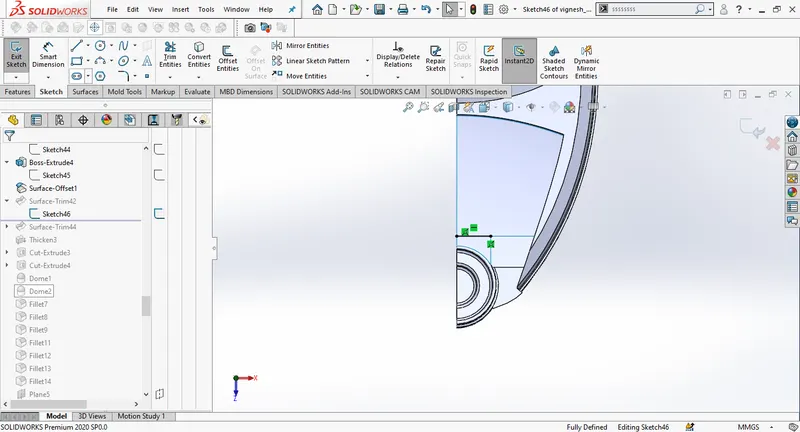
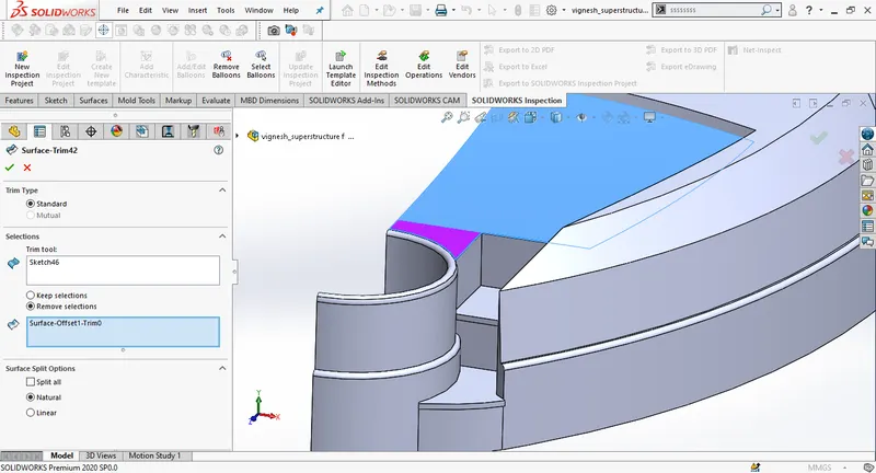
Create a new sketch on the top plane by offsetting the edges of the blue surface, change the offset distance 5mm inwards, use surface tirm to saperate the surface enabling keep selections. Use thicken to increase the surface thickness.
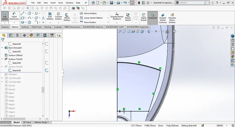
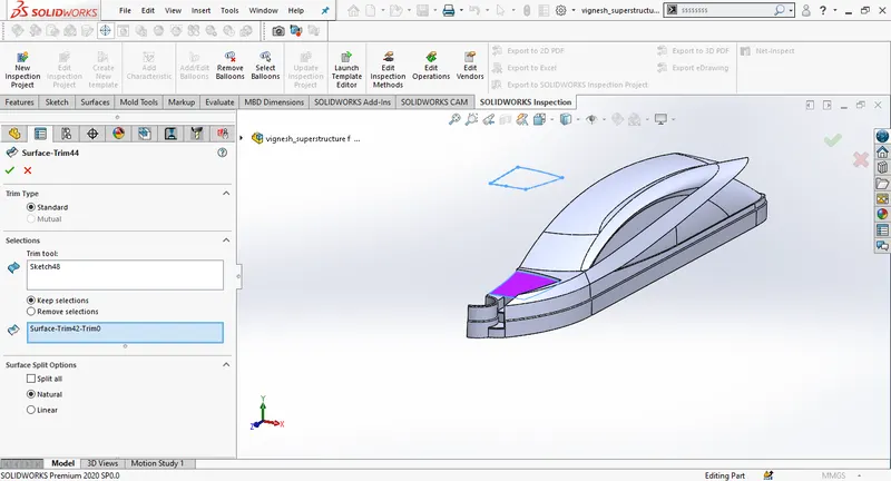
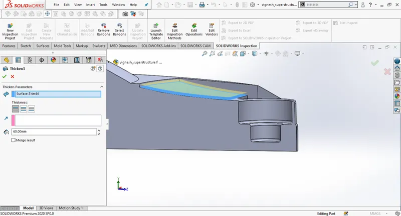
Draw a new sketch on the top plane, offset the curve, then create an extrude cut, change the direction as offset from surface
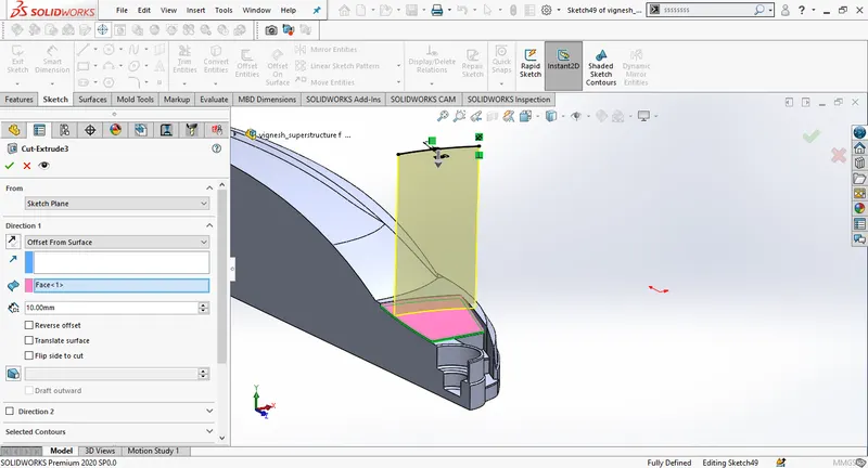
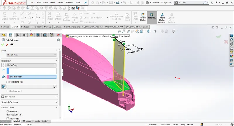
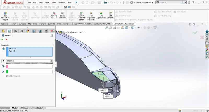
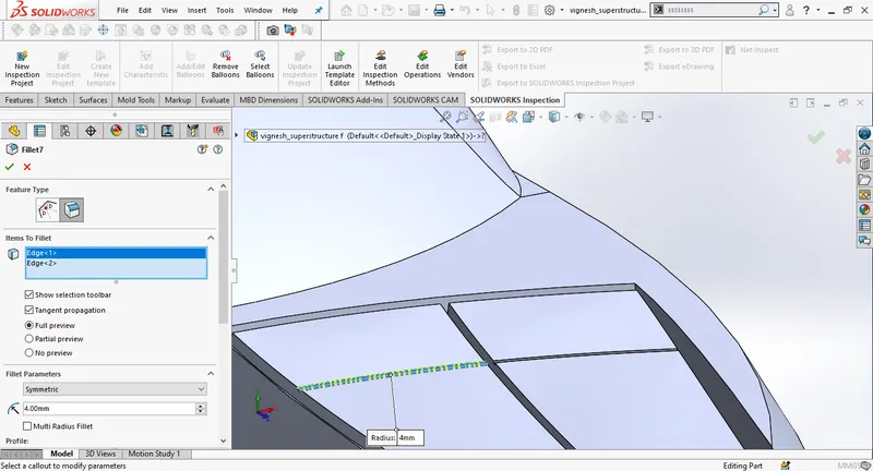
Create a new plane to draw a new sketchto design railing aroung the front part of the superstructure.
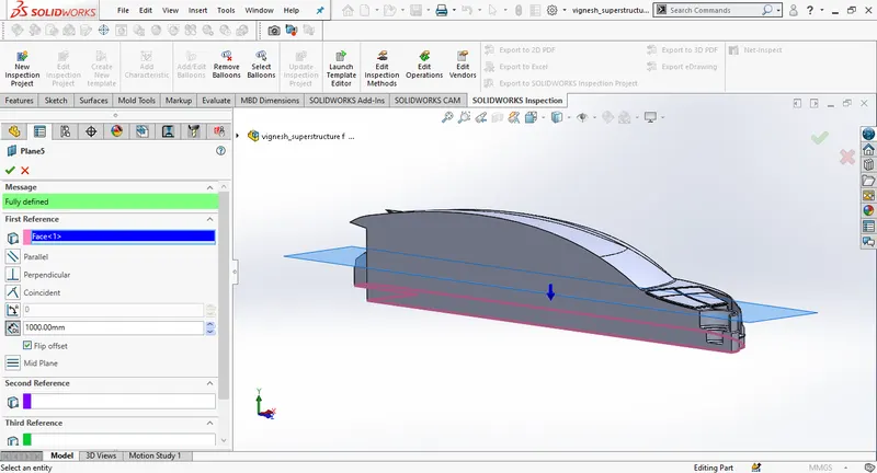
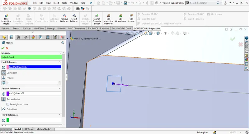
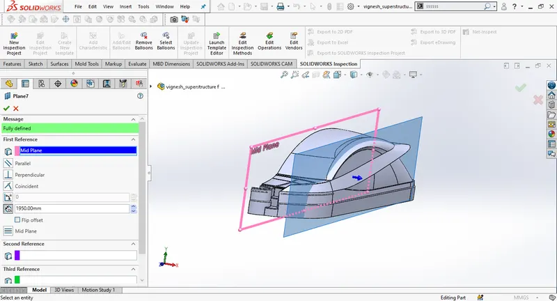
Create a new plane using mid plane as referance
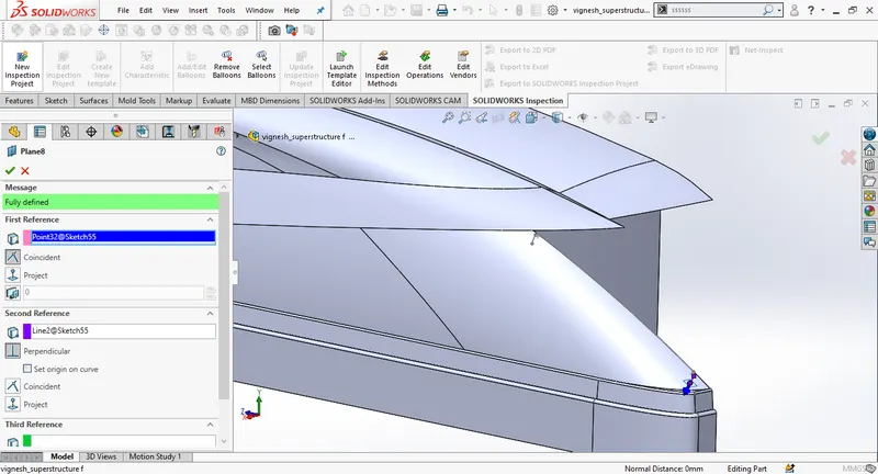
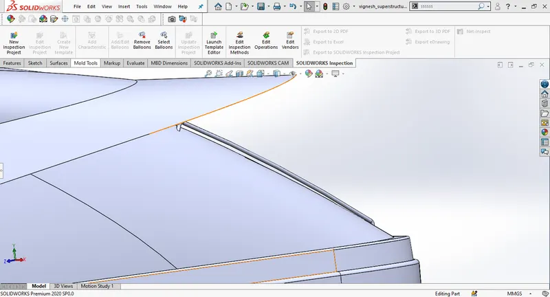
Create an extrude cut . Draw a new sketch on the back plane then use extrude cut to make the back doors of the superstructure. Create another plane and draw a new sketch to make door handles.
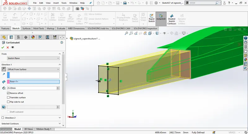
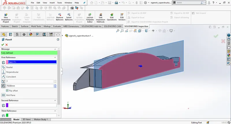
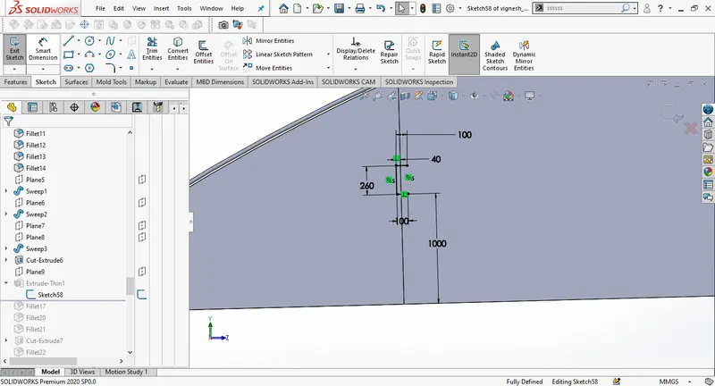
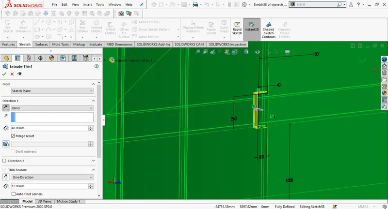
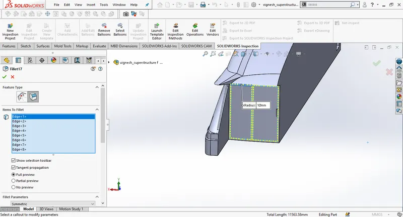
Draw a new sketch on the top plane and then use extrude cut.
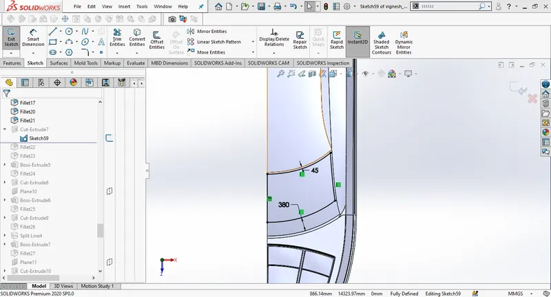
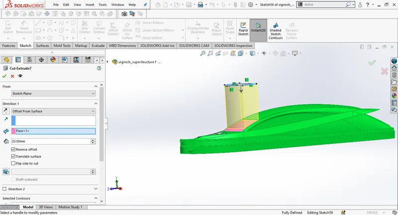
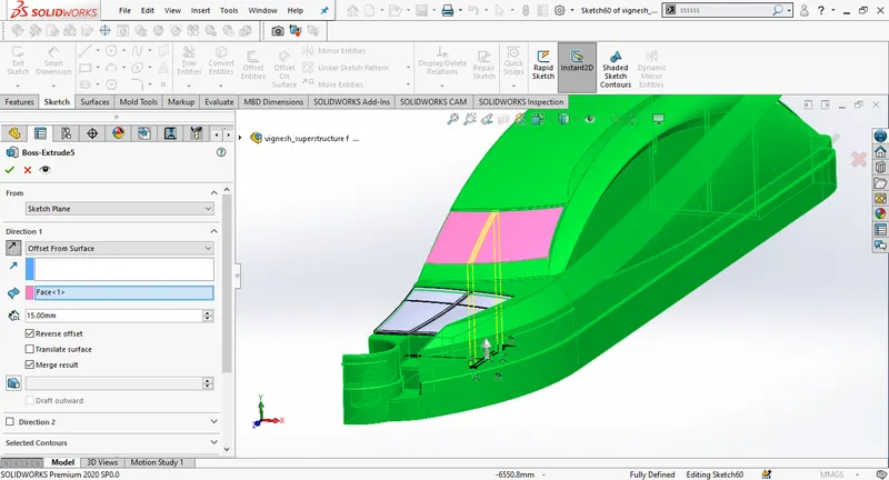
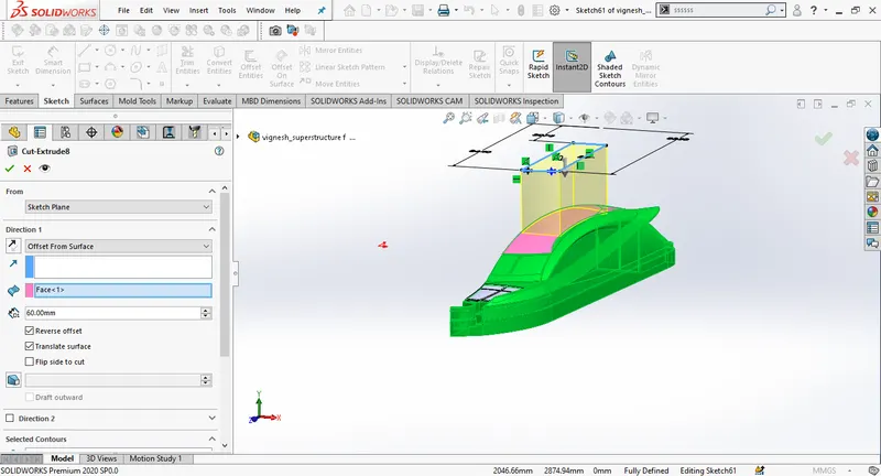
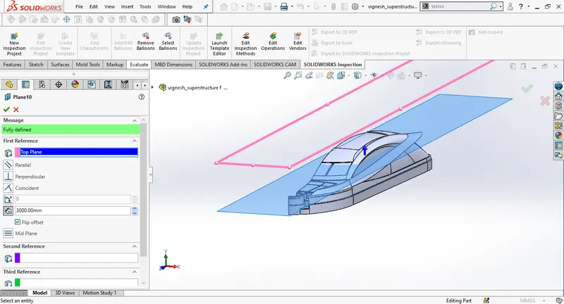
Create a new plane with top plane as its first referance, then create a cut extrude to make a sunroof for the superstructure.
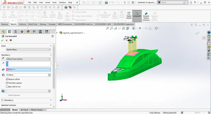
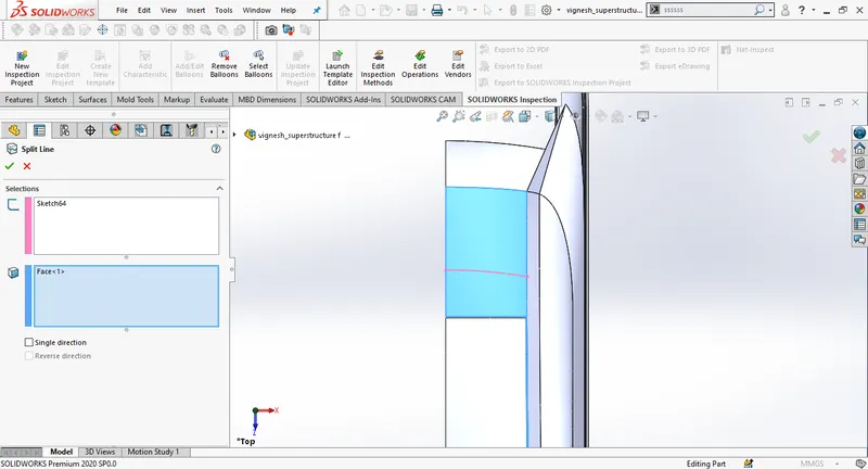
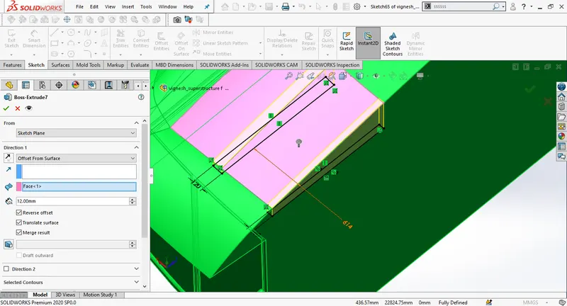
Create a new plane with mid plane as the first referance, create an extrude cut to add more detailing to the side window.
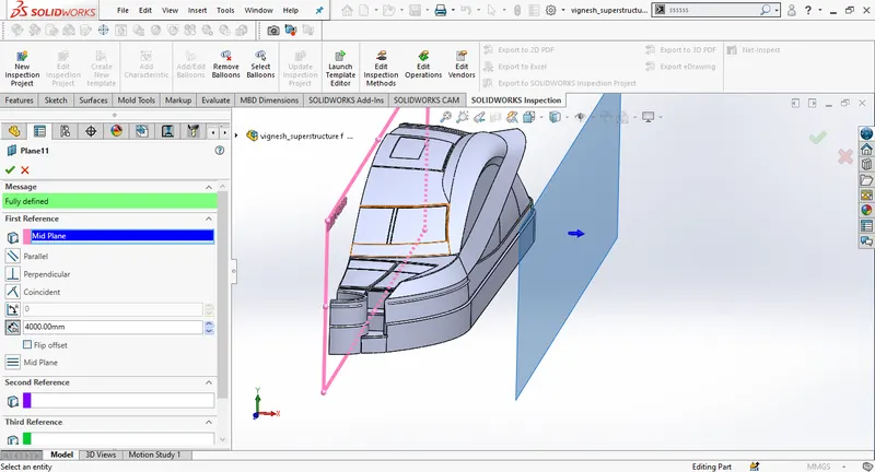
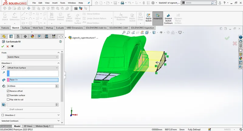
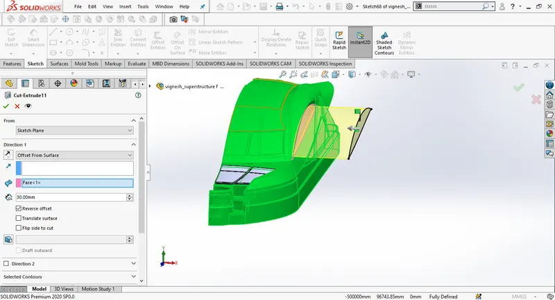
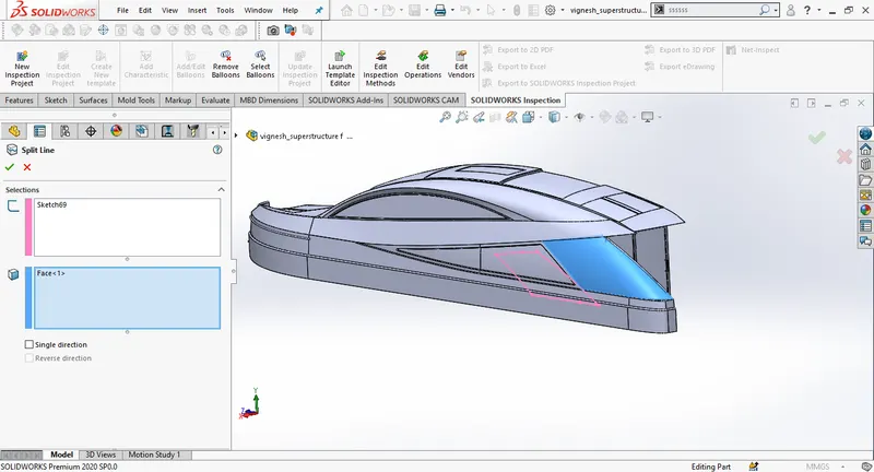
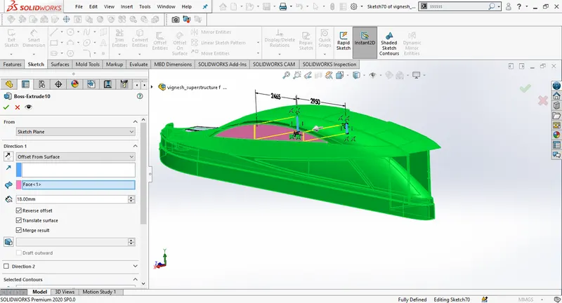
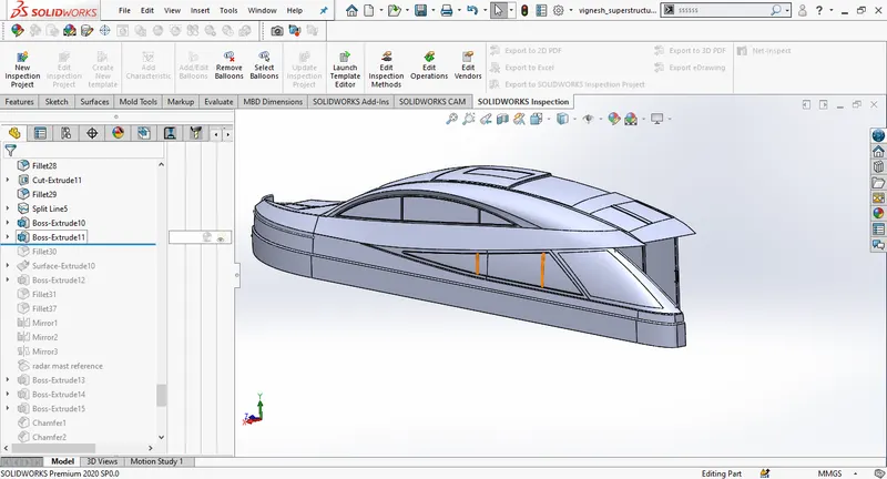
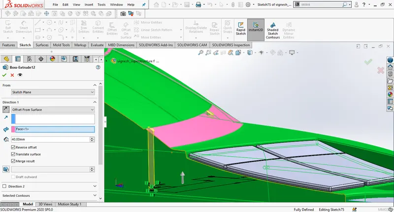
Mirror the main body of the superstructure, select mid plane plane as mirror plane.
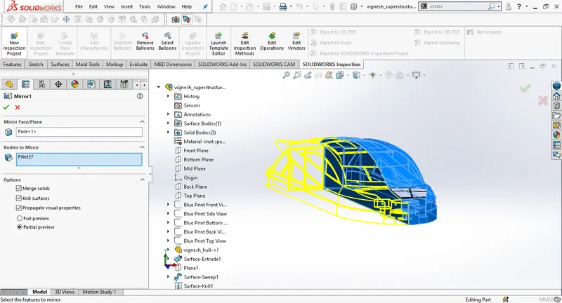
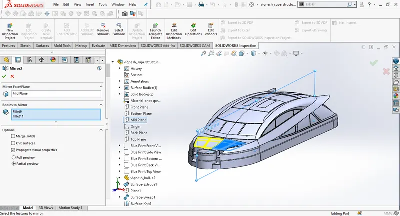
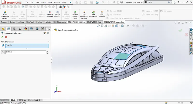
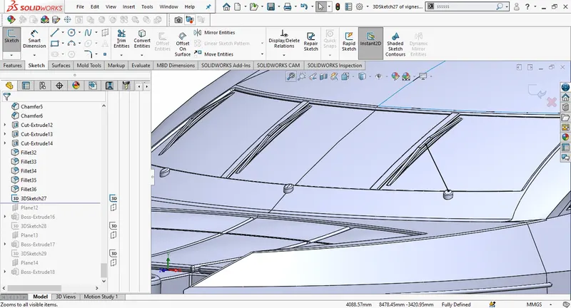
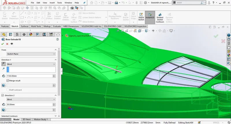
Create a 2D sketch on plane 5. then create an extrude boss for wipers. Give required champher.
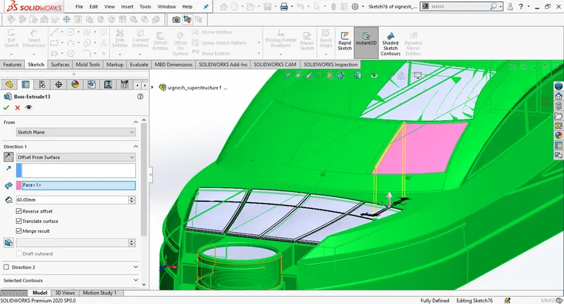
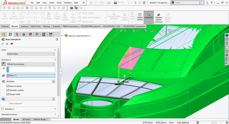
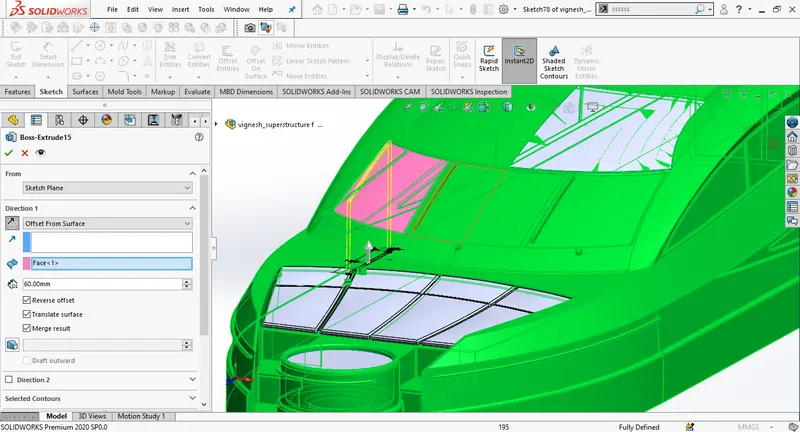
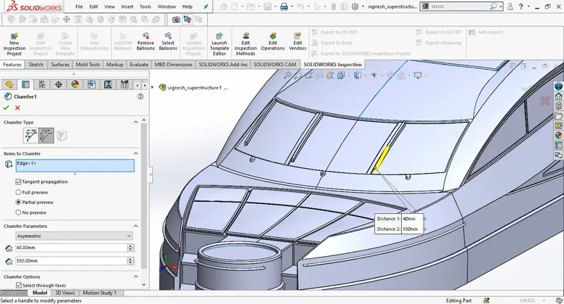
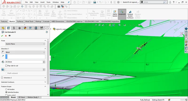
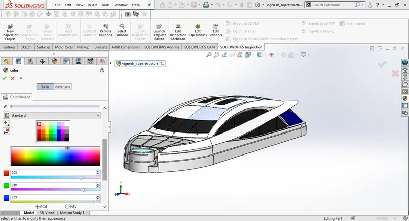
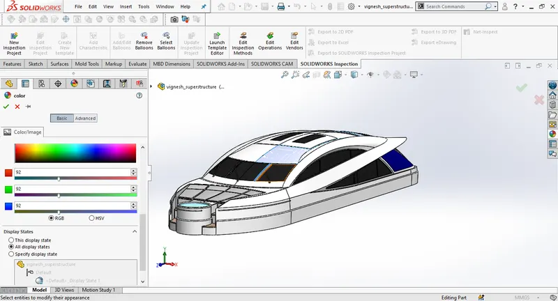
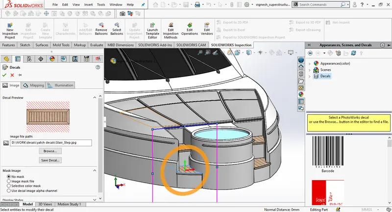
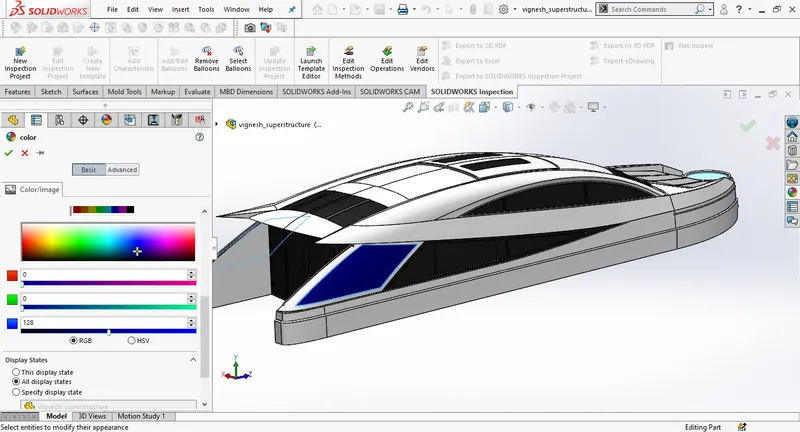
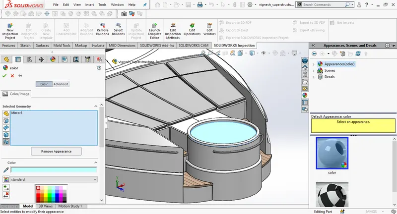
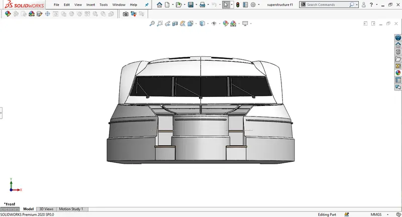
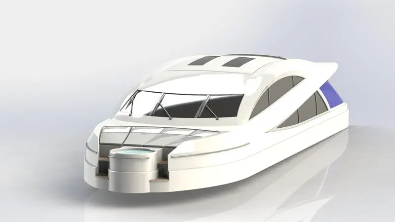
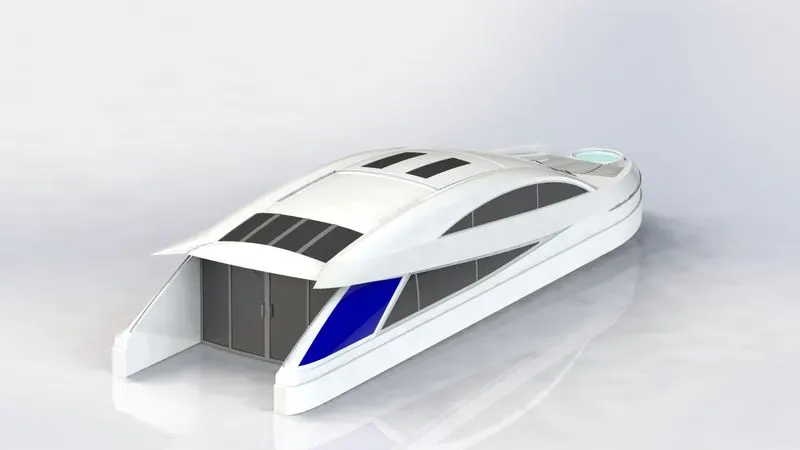
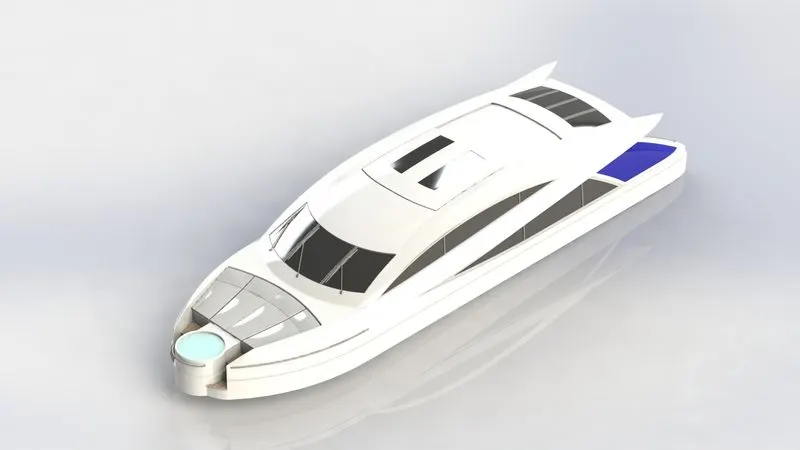
Then create an extrude cut by sketchig on the side face of the vipers. Draw a 3D sketch to connect vipers then create a new plane at the bottom end of 3D sketch to create a solid sweep. Add appearances and decals for stairs at the end to finish.
RADAR MAST:
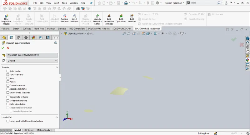
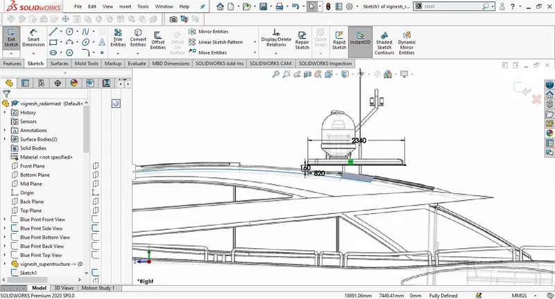
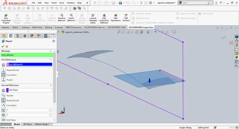
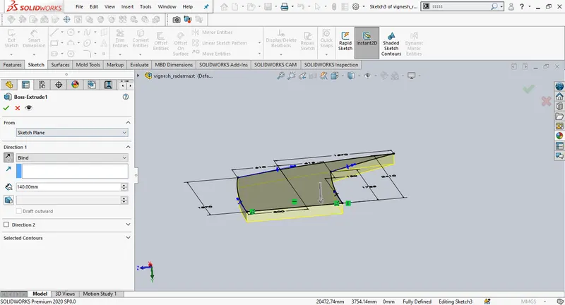
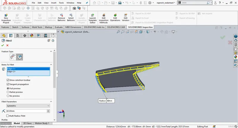
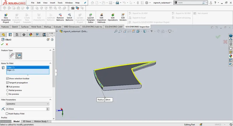
To design radar mast import the top surface of the superstructure. Select the midplane and using bluprint side view draw a sketch, add dimensions. Insert a new plane and draw a new sketch on the new plane. Create an extrude for the sketch, change the depth to 140mm and the extrude should be facing upwards. Add fillets at the end.
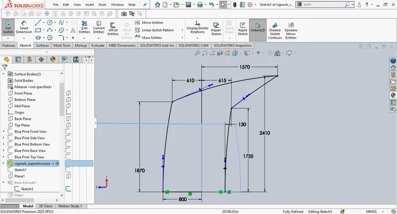
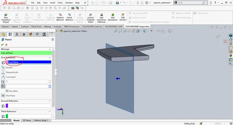
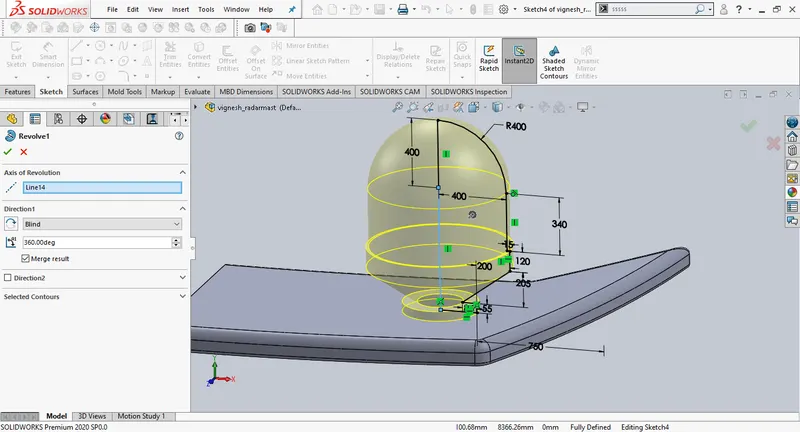
Create a new plane using front plane as first referance change the offset distance to 20960mm, create a new sketch on the plane 2, then create a revolve.
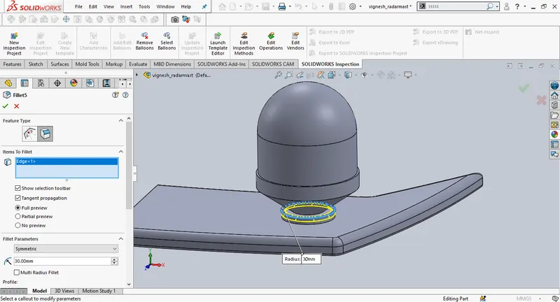
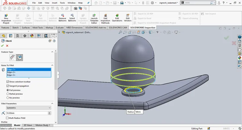
Draw a new sketch on the base surface, draw a circle of 50mm diameter and create an extrude, change the depth to 345mm. Create another extrude on the top of the previous one with 30mm dia and extrude depth of 50mm. similarly create another extrude eith 10mm dia and extrude depth of 1800mm.
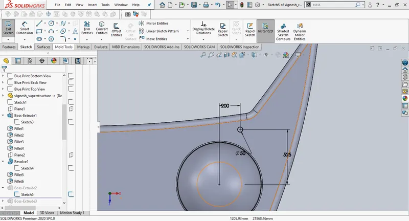
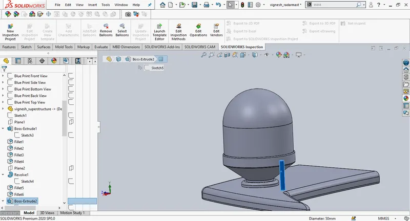
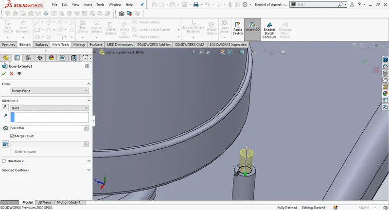
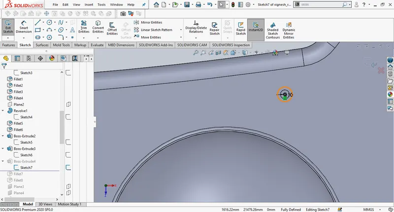
Create a new plane using plane 2 as first referance and change the offset distance to 250mm. Create a new sketch on the plane 3, draw a spline and match the curve close to the blueprint. Create a new plane using the endpoint of the spline as the first referance, draw a new circle on the new plane, then create a solid sweep. Mirror the sweep.
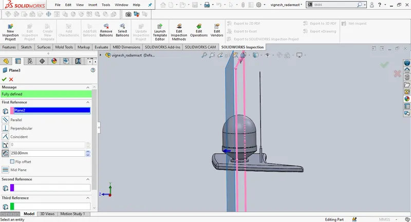
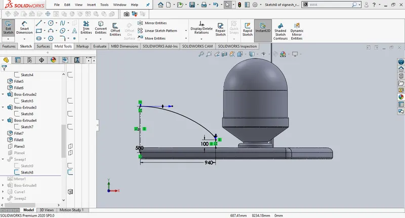
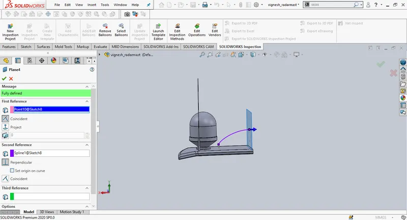
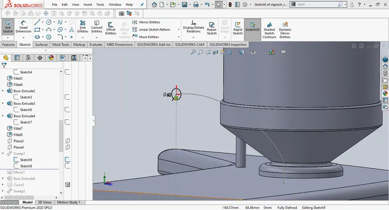
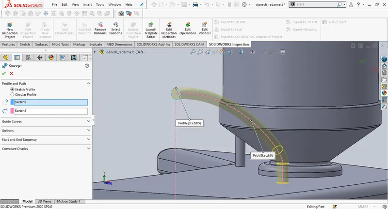
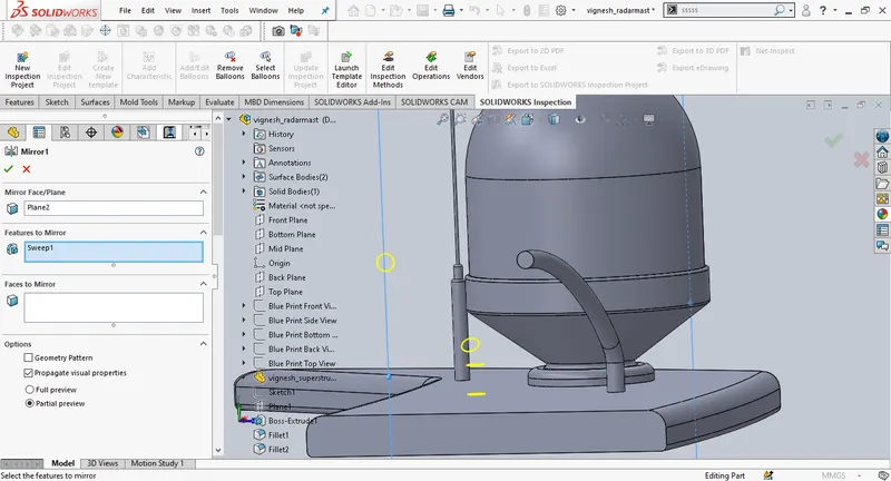
Create a new sketch on plane 2, create an extrude.
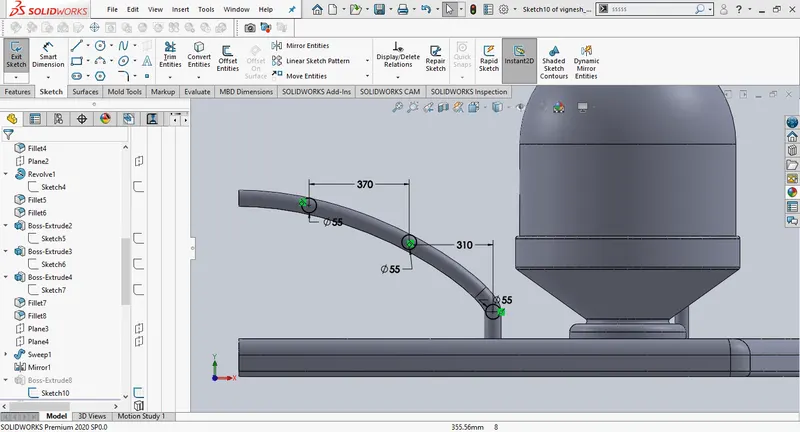
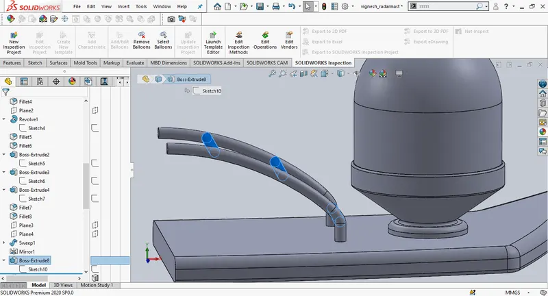 .
.
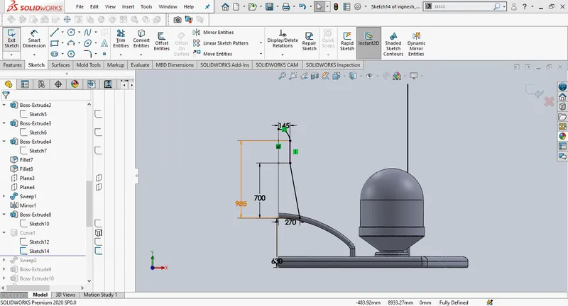
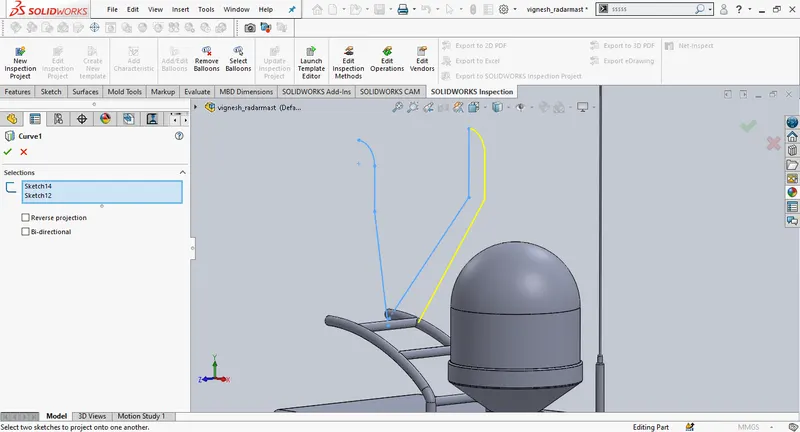
Draw a new sketch on the midplane, draw a new sketch on plane 2, create a projected curve using both the sketches.
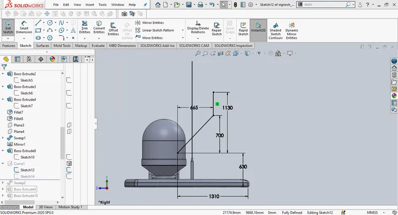
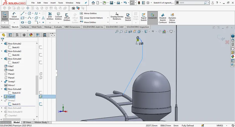
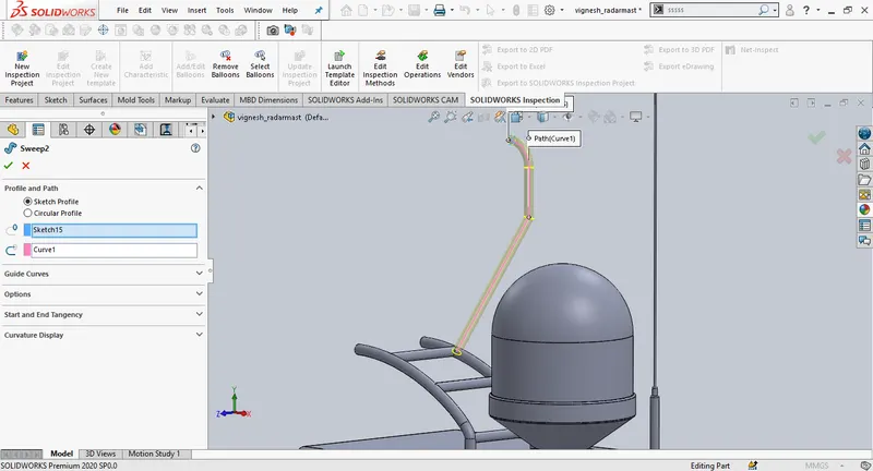
Draw a new sketch on the midplane, use pierce relation to define the sketch, create a solid sweep.
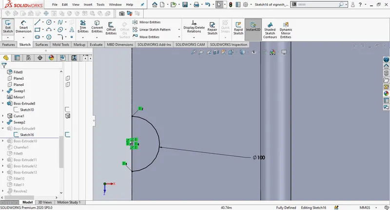
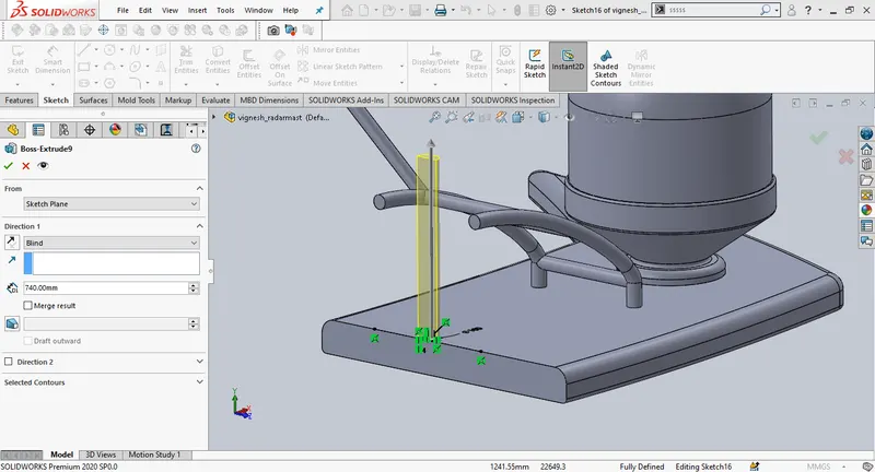
Create a new sketch on the bottom surface draw a semi circle, create a boss extrude, change the depth to 740mm.
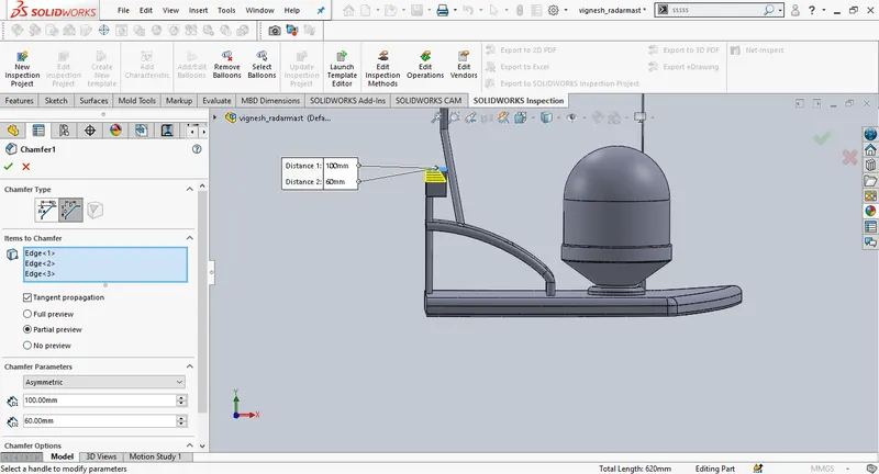
Create a new boss extrude by sketching on the recent extrude, give reqired chamfer.
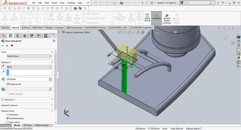
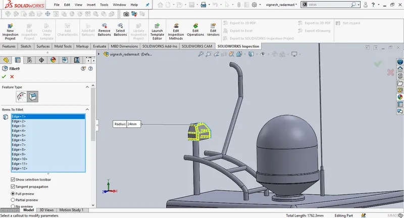
Create a new sketch on midlane, create a boss extrude change the direction to "upto surface"
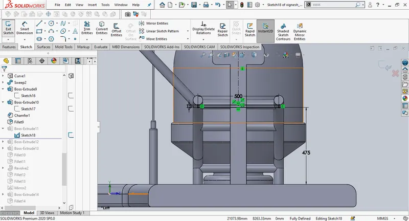
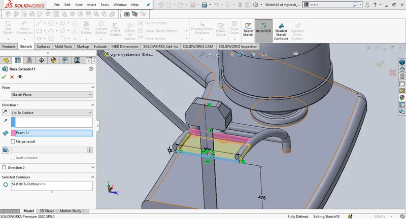
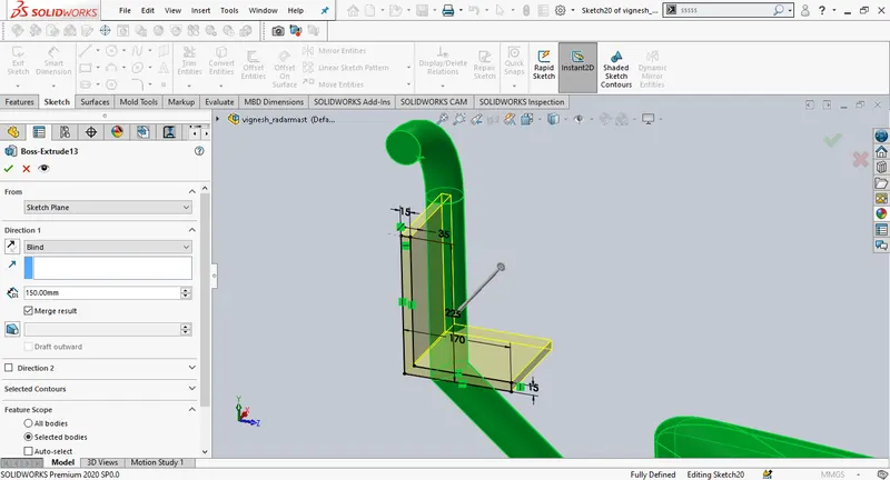
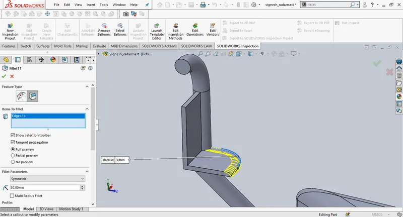
Draw a new sketch as shown in pictures and create a boss extrude.
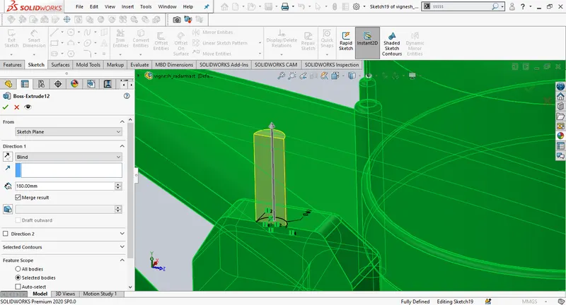
Create a revolve by sketching on the midplane. Use revolve to create round surface. Add fillets and then mirror the mast light.
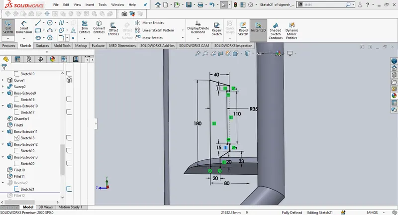
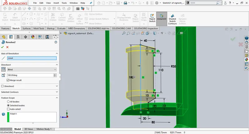
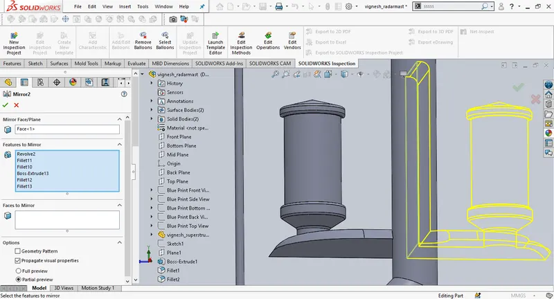
Create a new sketch on the downward side of the mast, create an extrude.
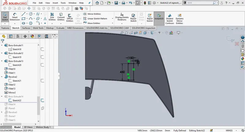
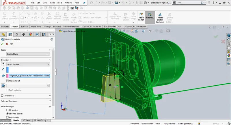
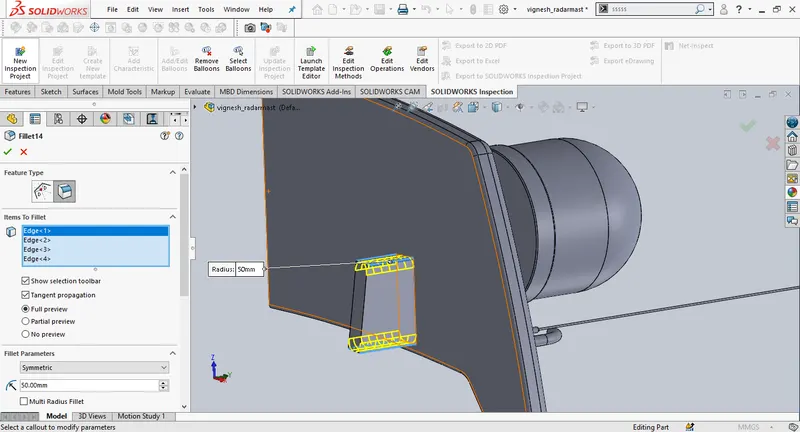
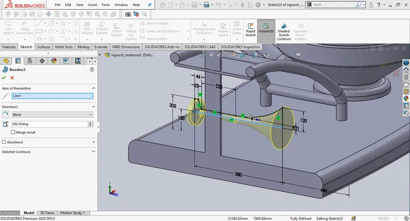
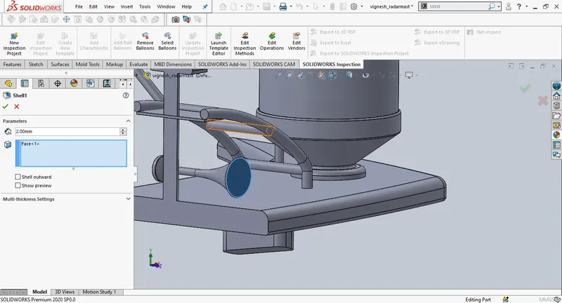
Create a new plane setting midplane as first referance, change the offset distance to 270mm. Draw a new sketch on the new plane, use revovle to design horn. Then create a shell.
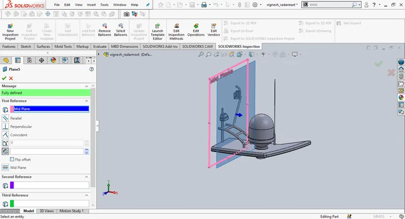
Mirror the radar mast by selecting midplane or face as mirror plane.
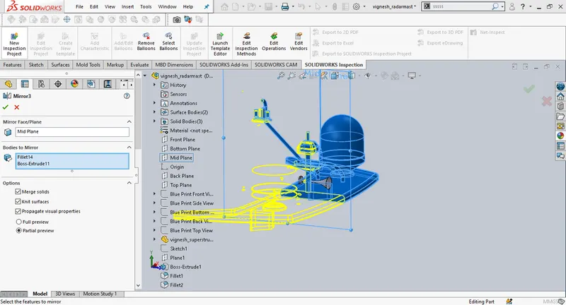
Draw a new sketch and create an extrude to design horn mounting. Create a new plane and mirror features across the new plane.
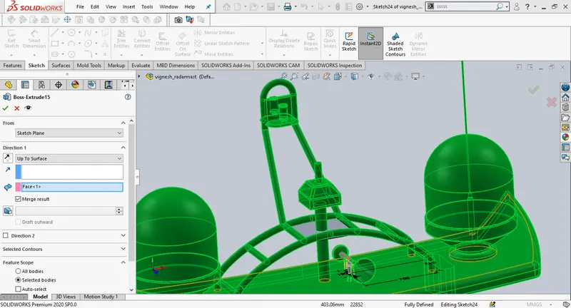
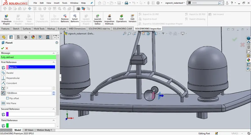
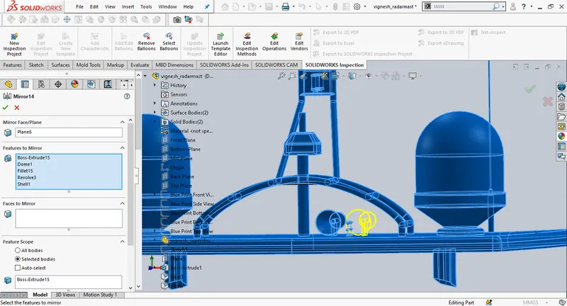
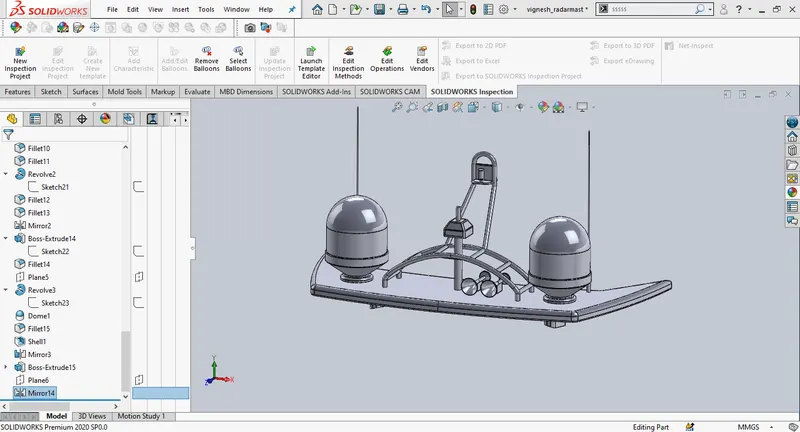
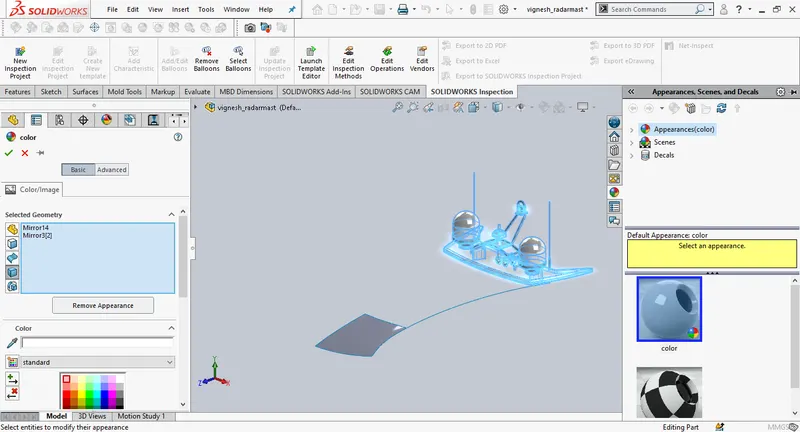
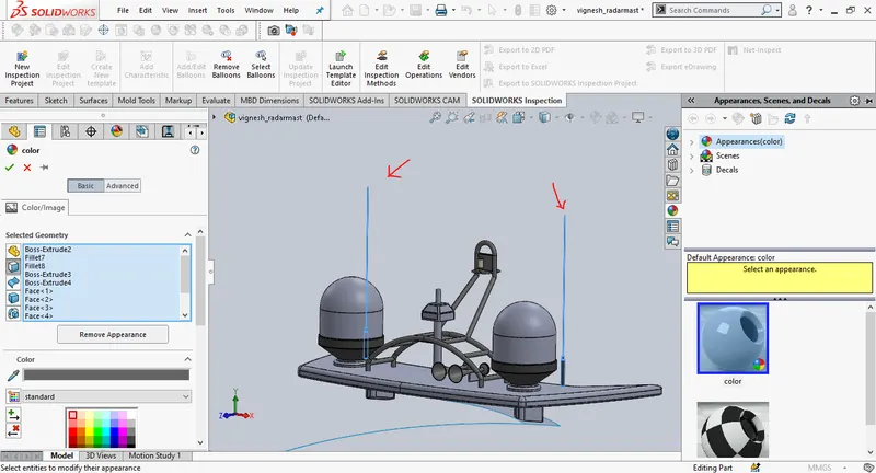
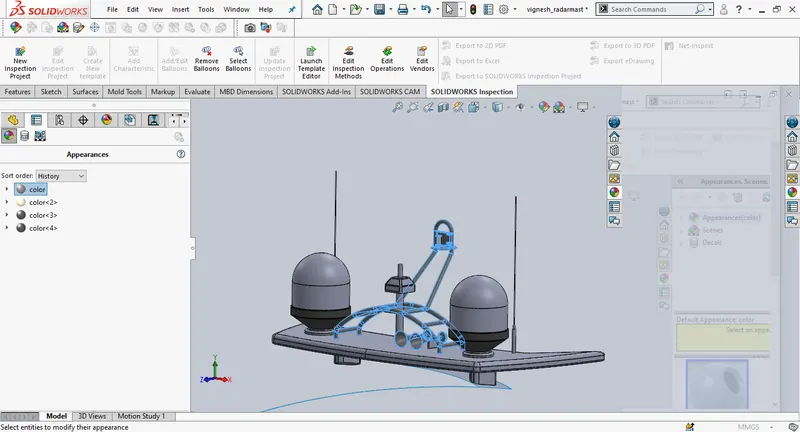
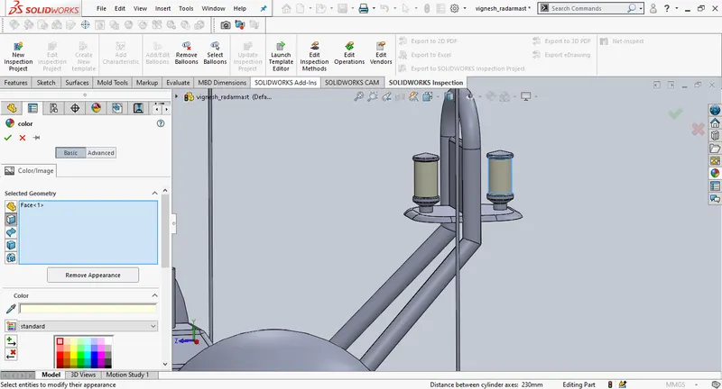
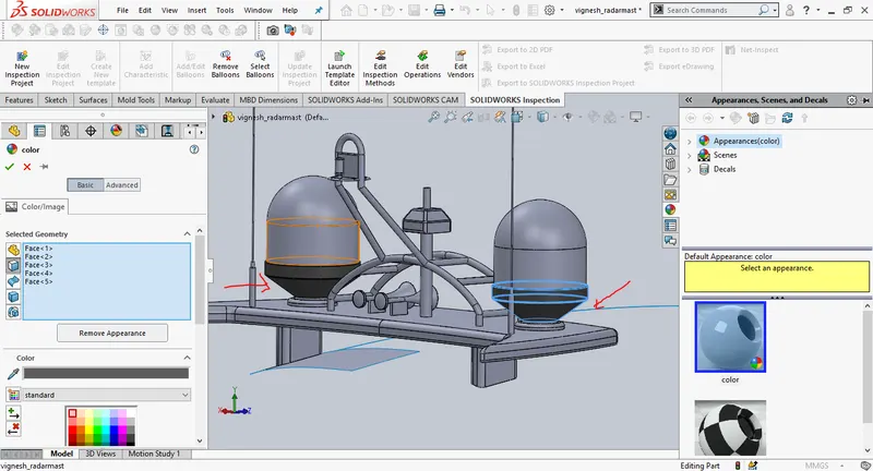
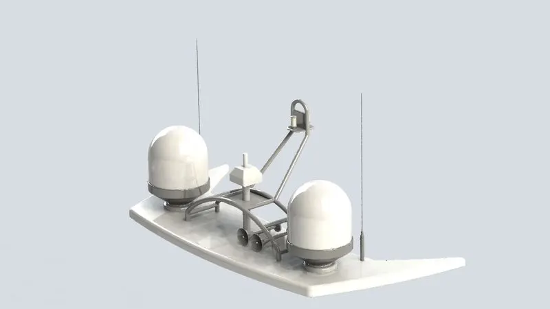
Add appearences in the end.
ASSEMBLY:
Assembly of the yatch is simple as the entire design is created with exact referances. To assemble all the solid parts created open assembly in solidworks. Import hull part at the begining and select ok, the part automatically gets fixed in the assembly. Similarly import all the parts created in the assembly, all the parts are fixed automatically except the propellers as every part is created with referance to each other. Propellers and garage door are inserted manually using concentric and coincident mates.
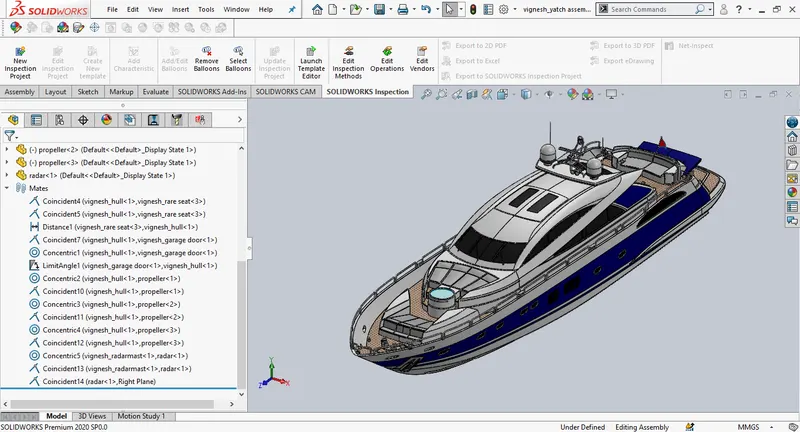
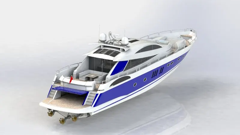
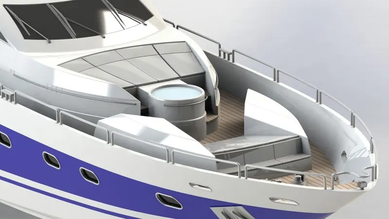
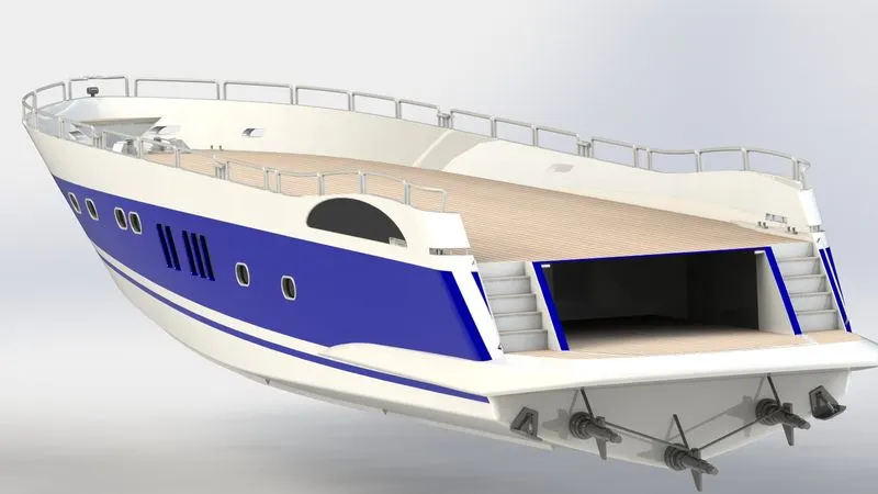
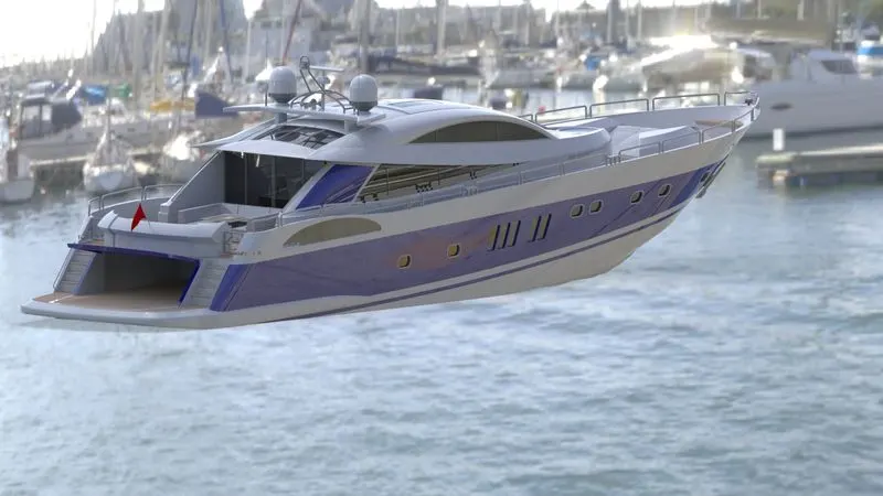
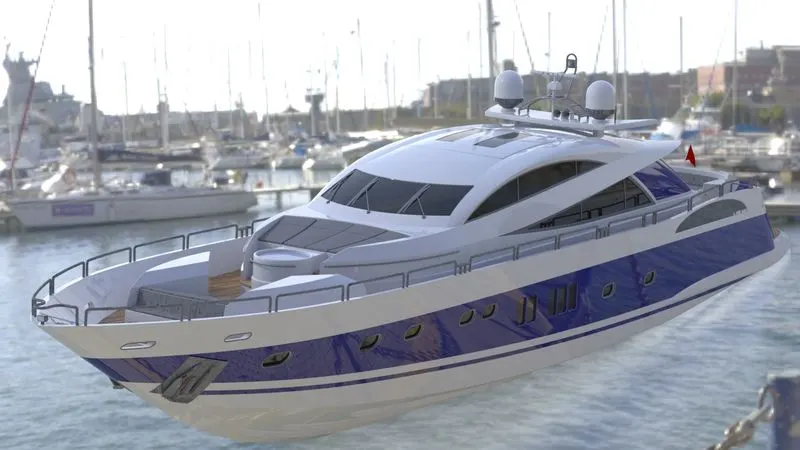
Using solidworks vizualize create renders for yatch using HDRI envoirnment.
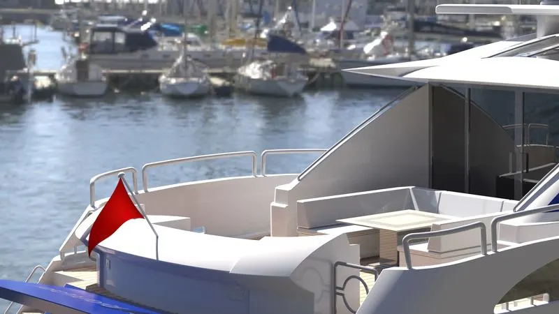
CONCLUSION:
By the end of the design process, one can exactly get how to create surface bodies, the most challenging part is the superstructure, whlie designing the superstructure we use almost use every feature in surface modelling.