Advanced Sheet Metal Design Using NX Cad Challenge_1_Casing Design
SHEET METAL CASING
OBJECTIVE:
The main objective is to design casing and obtain flat pattern using NX Sheet metal application.
Introduction:
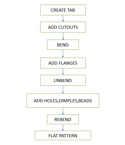
Here is the flow chart about how the design procedure for casing is done.
Design procedure:
CREATING TAB:
Open NX software select modelling, then select the xy plane and draw a rectangle of length 60mm and width 50mm with center as origin. Start sheet metal and set the design parameters to 1mm, using tab command select the sketch this will add thickness to the sketch.
ADDING CUTOUT:
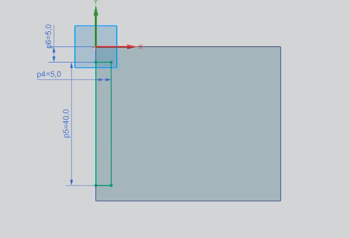
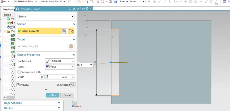
Create a new sketch on the top surface of the tab, draw another rectangle keeping it fixed to the left edge.
BENDING:
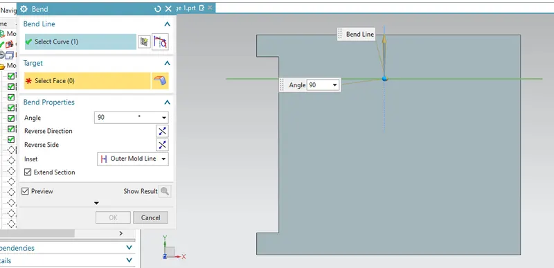
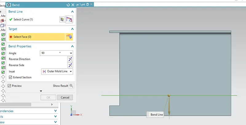
Draw a horizontal line selecting on the top face of the tab. The line must be placed 10mm from the top edge.Select the bend command set bend angle to 90 degrees and select the previous sketch. Repeat the same process to create another bend as shown in the figure.
ADDING FLANGES:
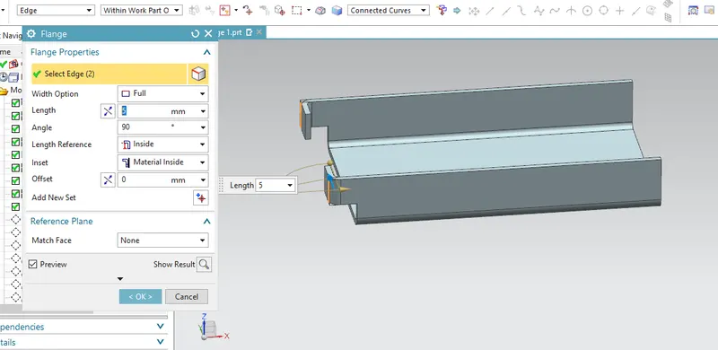
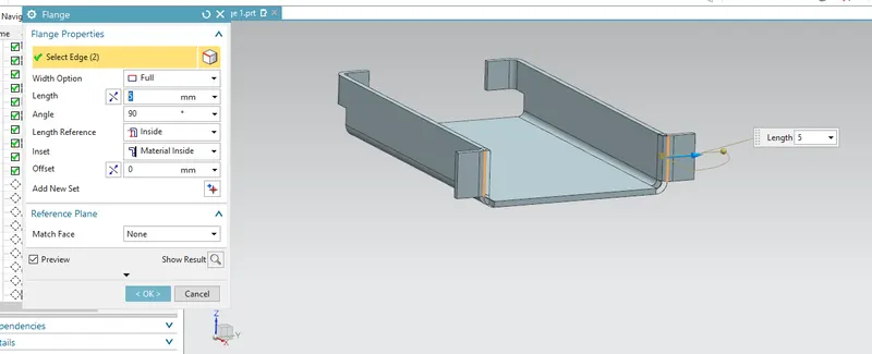
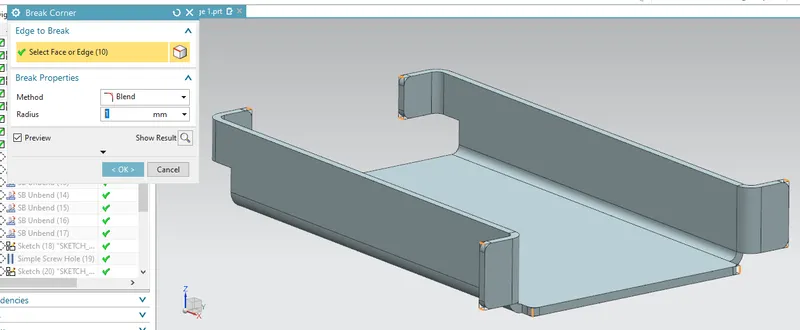
Sekect the flange command and set the flange length to 5 mm, then select the two edges , the flanges should be falling inwards as per design. Repeat the same procedure for creating the flanges on the opp side, but this time the flanges should be falling outwards. Select the breaking corners from the command bar and select the edges which need to rounded.
UNBEND:
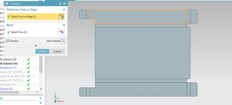
Unbend the model using unbend command. carefullu select the order of unbending as the rebinding must be done in reverse order.
ADDING HOLES:
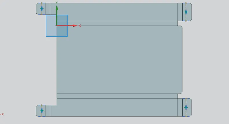
Draw a sketch on the flanges, using a line and its mid point mark a point using point from the command bar under sketching section. Repeat the same procedure for drawing four points. Then select hole command and set the required parameters and select the four points.
ADDIND DIMPLE:
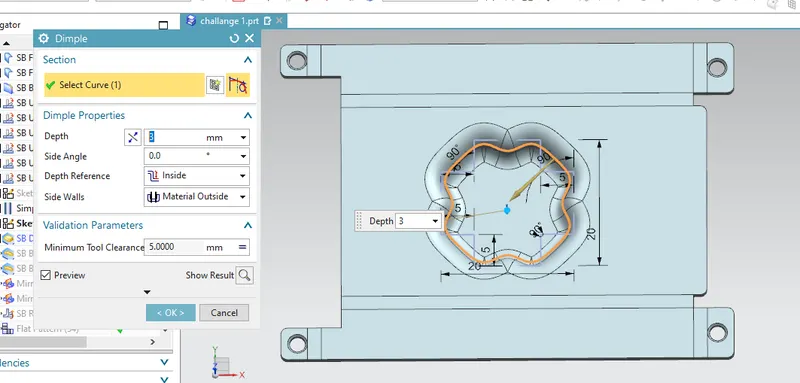
Draw a new sketch to create a dimple in the model. Draw a square of side 20mm with origin as its center. Now use quick trim to delete the unwanted edges. Then select studio spline from more options under sketch command. Select all the 16 edges of the sketch in either clock wise or anti clock wise direction. Use move curve to specify the origin. Select dimple command and set required parameters, select the curve and then click ok.
ADDING BEADS:
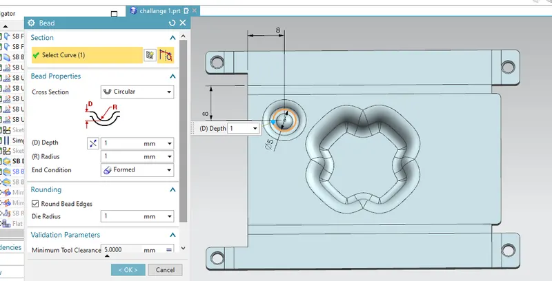
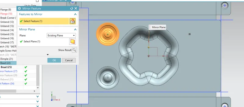
Add a new sketch on the plane p, draw a circle of diameter 5mm. Select bead commad and set the parameters and direction, then exit. Create any two beads and using mirror feature copy it for the other side.
REBENDING:
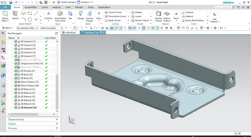
Now using rebend, rebend the faces of the model in the reverse order in which they were bend.
DRAFTING:
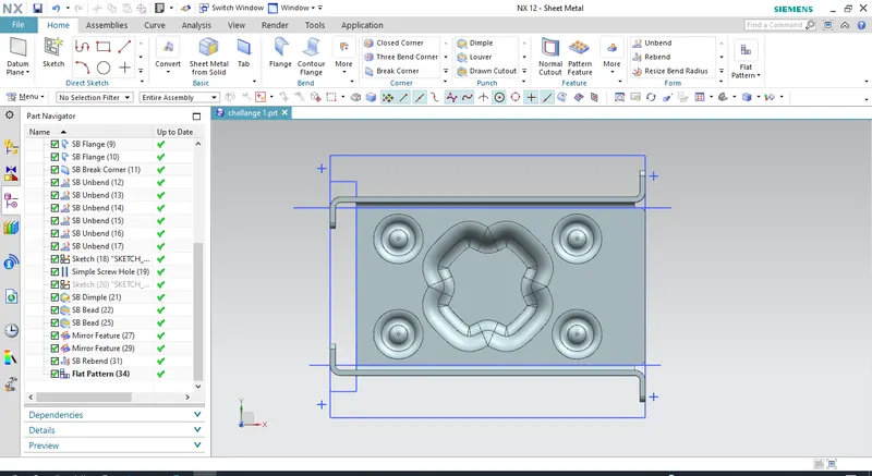
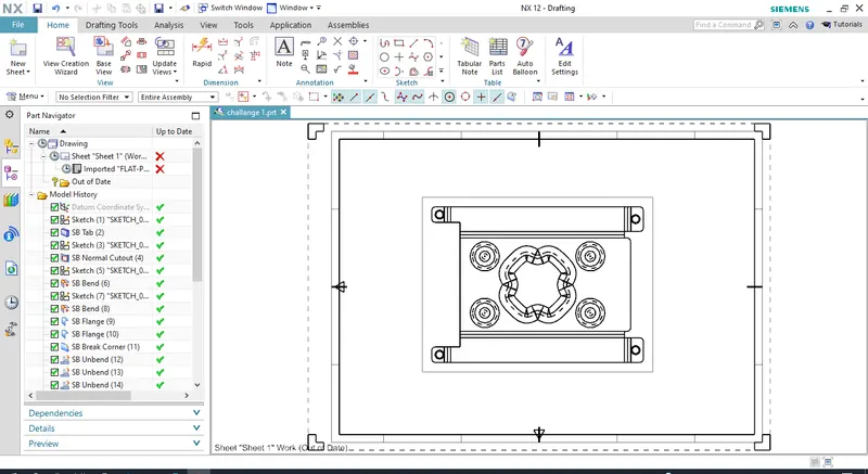
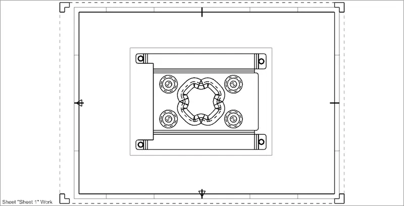
Create a flat pattern using flat pattern command. select the center face of the model to create the flat pattern, If the flat pattern is not visible go to the drafting, select all the required parameters.
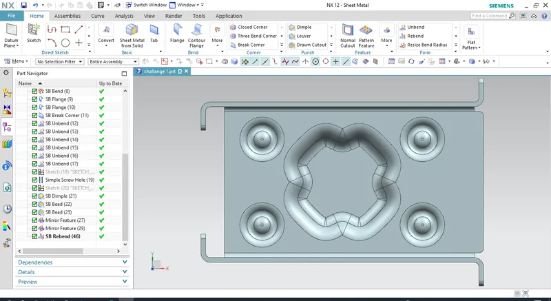
FRONT VIEW:
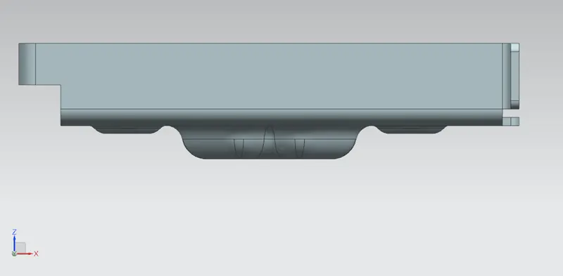
SIDE VIEW:
ISOMETRIC VIEW:
FLAT PATTERN:
CONCLUSION:
Design procedure in sheet metal, understanding of various commands like, Sketching, tabs, flanges, bend, unbend, rebend, dimple,beads and how to create a flat pattern.