Week 9 - Project 1 - Door Trim Lower with Engineering Features
Aim: To create the Door Trim Lower Plastic component through the given Class-A surface and the Heat Stakes and the locators for the Closed body.
Heat staking:
- Heat staking also known as thermoplastic staking is the process of joining two dissimilar materials together. In heat staking, we use local heating and cooling to raise the temperature of plastic components and allow plastic reforming to be carried out.
Locator:
- The locator is used to guide the mating part into its perfect position so that all the features will match each other.
- 4-WAY LOCATOR: 4-way means you prevent movement at 2 axes (+X, -X, +Y, and -Y) on the plane.
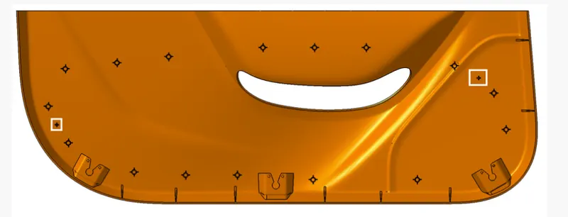
Given reference image:
Tooling axis:
- The axis is the direction in which the mold opens or else the core and cavity open. The tooling axis should help to clear components from the core and cavity, so it plays a very crucial role in plastic designing and manufacturing also.
Draft Angle:
- Draft angle is the degree of taper that is incorporated into the side wall and part, core, and cavity of the die-cast tool to aid in the removal of a part. Primarily, their function is to reduce the friction between the part and the tool as it is ejected. Without draft angles, parts can be stripped, dented, or get stuck in the tool.
- Draft angle also reduces the friction between the part, core, and cavity and also reduces the production time as it is easy to reject the part from the core and cavity.
Draft Analysis:
- As the name suggests, draft analysis is nothing but checking the draft angle range i.e., whether the angle is in the ideal range of 3 degrees or not.
- In this analysis we have a colour scale where we can see the range of a specific colour and we can even change the range by double-clicking on the number.
- To do draft analysis go to insert-Analysis-Featured Draft analysis.
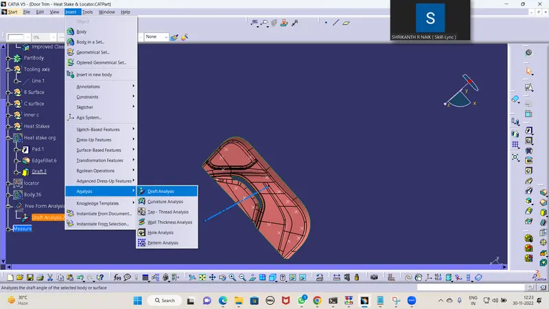
Steps to create a Main tooling axis by using the bisecting method and draft analysis concerning the tooling axis:
- First of all to create a tooling axis, check all the directions of the component to find the best tooling axis direction and in the given component the Y direction is the best where no interference in clearing the tooling axis.
- Create a point on the Surface of class A and Create a line that acts as a Tooling axis.
- Then check with a draft analysis whether the part is clearing the tooling axis or not.
- For that we should select the draft analysis option and pick the compass and place over the main tooling axis and select the Part body now we can see the color grading over the part according to the range given in the color scale.
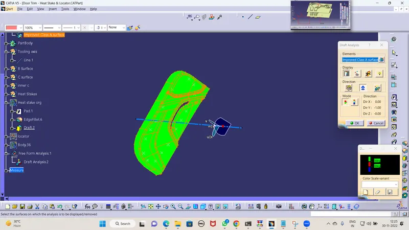
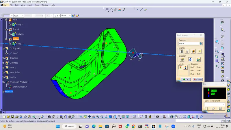
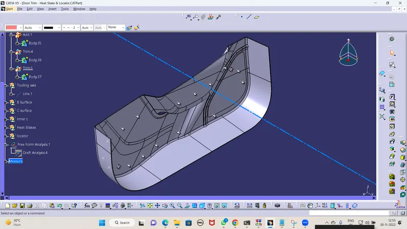
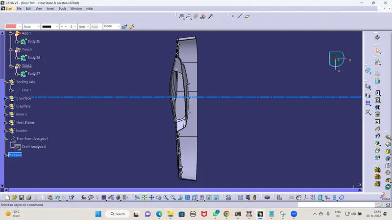
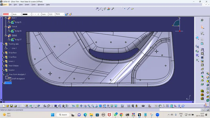
Screenshots of the completed design in various orientations (Isometric, Front, Side, and Top View):
- Heat Stake and Locator:
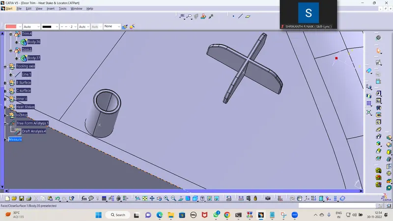
- Isometric View:
- Top View:
- Front View:
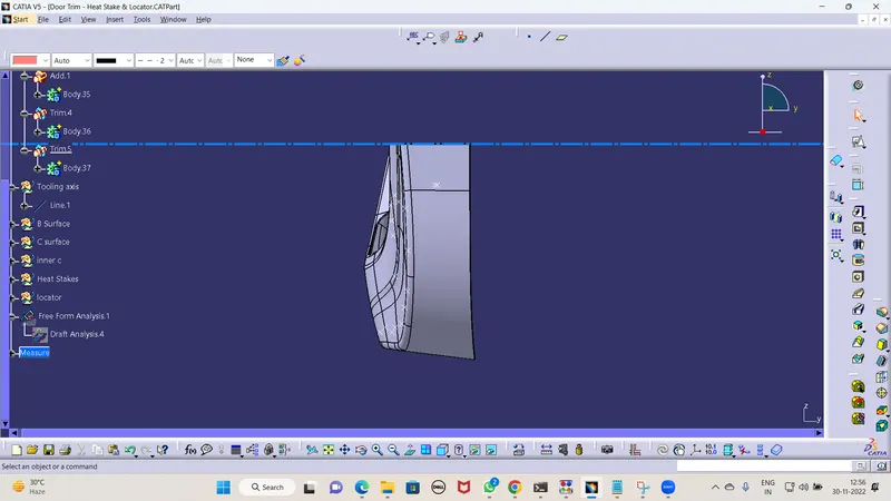
- Side View:
Conclusion:
Hence all the submission requirements are successfully done and the CATPart file is attached below using Browse option.