Week 9 - Attachment Feature Creation (Ribs & Screw Boss) - Challenge 1
Aim: To create the rib and screw boss for the Drill Handle.
Tooling axis:
- The axis is the direction in which the mold opens or else the core and cavity open. The tooling axis should help to clear components from the core and cavity, so it plays a very crucial role in plastic designing and manufacturing also.
Draft Angle:
- Draft angle is the degree of taper that is incorporated into the side wall and part, core, and cavity of the die-cast tool to aid in the removal of a part. Primarily, their function is to reduce the friction between the part and the tool as it is ejected. Without draft angles, parts can be stripped, dented, or get stuck in the tool.
- Draft angle also reduces the friction between the part, core, and cavity and also reduces the production time as it is easy to reject the part from the core and cavity.
Draft Analysis:
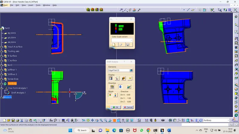
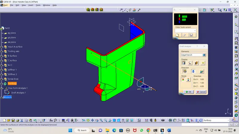
- As the name suggests, draft analysis is nothing but checking the draft angle range i.e., whether the angle is in the ideal range of 3 degrees or not.
- In this analysis we have a colour scale where we can see the range of a specific colour and we can even change the range by double-clicking on the number.
- To do draft analysis go to insert-Analysis-Featured Draft analysis.
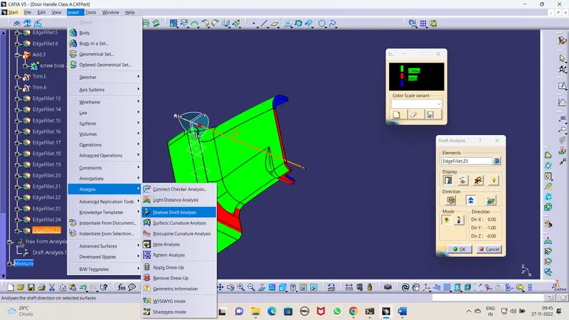
Steps to create a tooling axis by using the bisecting method and draft analysis concerning tooling axis:
- First of all, check all the directions of the component to find the best tooling axis direction and in the given component the Y direction is the best where no interference in clearing the tooling axis.
- Create a point on the Surface of class A and Create a line that acts as a Tooling axis.
- Then check with a draft analysis whether the part is clearing the tooling axis or not.
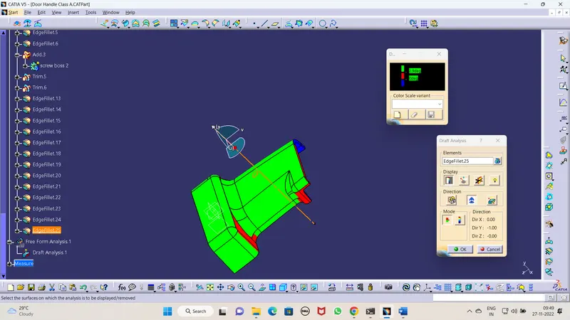
- Here in the given A surface there are surfaces where the draft angle is not given so the class A surface has to be changed.
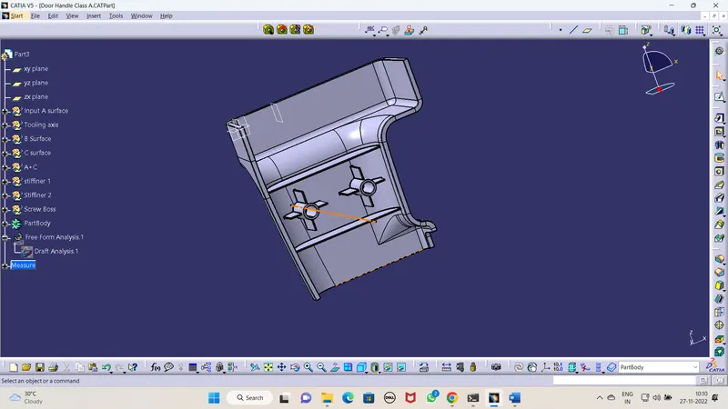
Screenshots of the completed design in various orientations (Isometric, Front, Side, and Top View):
- Isometric View:
- Top View:
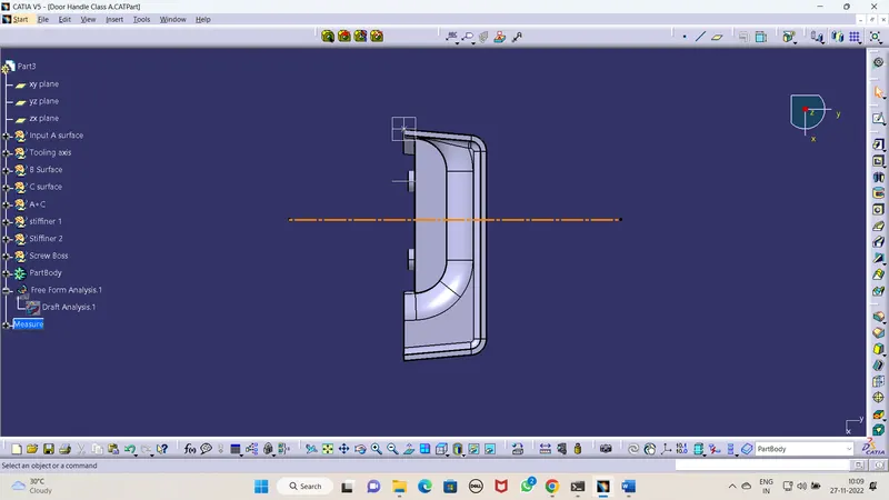
- Front View:
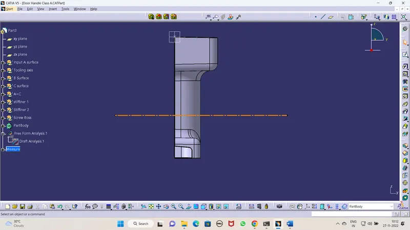
- Side View:
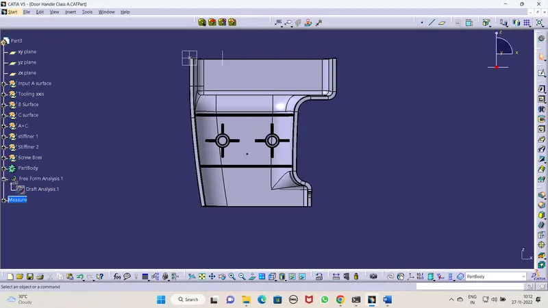
- Rib Design and Screw Boss:
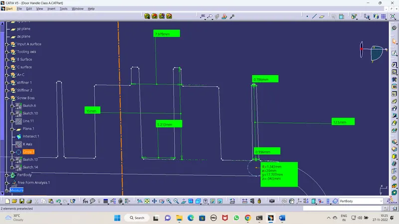
- Height of rib =>5t= 2.5*5=12.5
- Rib Thickness =>0.4*2.5=1mm
- Draft angle 0.5degree both sides
- Fillet 0.25mm max
- Inner dia of screw boss =5.2 mm
- Wall thickness of Screw Boss = 0.6*t=0.6*2.5=1.5mm
- height of Screw boss=height:dia=3:1=15.6:5.2
Conclusion:
Hence all the submission requirements are successfully done and the CATPart file is attached below using Browse option.