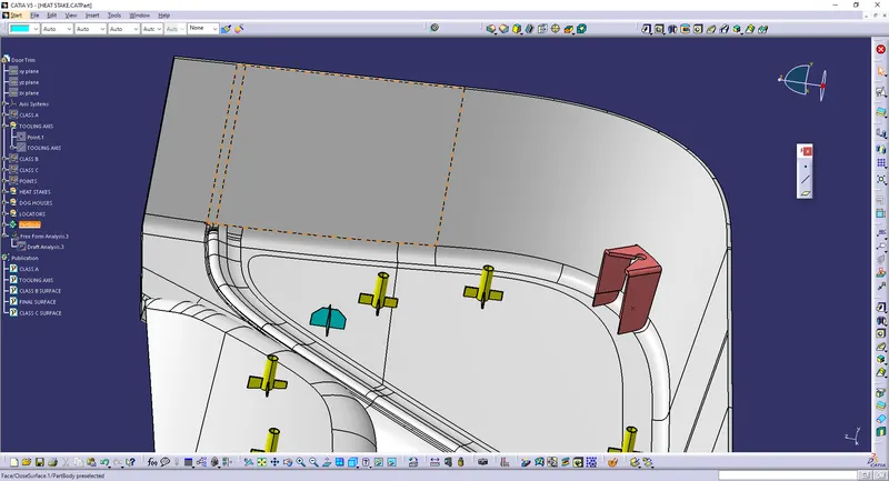
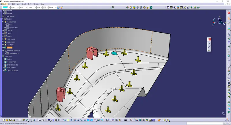
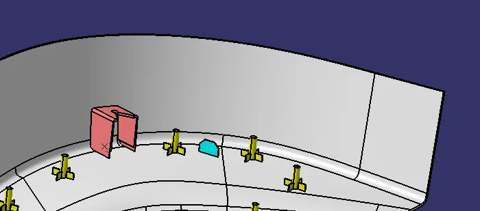
Week 9 - Project 1 - Door Trim Lower with Engineering Features
DESIGN OF CLOSED SURFACE AND TOOLING AXIS
AIM:Create the rib for the Drill Handle considering the design rules
PROCEDURE:
Part I
* Import the .STEP file into CATIA V5.
* fit the object to screen. Save the file into CATPART
*Open the file save it.
*use varnier tool to check the flat surfaces.
CREATING TOOLING AXIS
*By changing orientation and select a axis at which maximum part is visible.
*choose a surface and use point [•]
point >on surface >select a Surface >'0'
Choose line [/]
line point-direction select points Select axis
* The created line is the tooling axis Publish it.
Part II:
Offset → select the Class A Surface
*Click on the other side, so we obtain the.offset of A surface of 3mm which is considered as class B
*Fillet all the edges of required dimension
*class B surface is ready - Publish it
Part III:
* Make surface A visible and make boundary limit as required.
Sweep-> Using boundary and surface>90>and give okay
Now Join the Surface A &C.
*Use extrapolate . and completely check there is no open boundaries
*C surface is created and Join A+c and publish it
*Make the b surface visible and just extrapolate the extra edges
*Trim the extra surfaces and the required part of 3 mm thickness is created
*Go to Part Modelling Close surface → fill
* So the surface model is converted into part model.
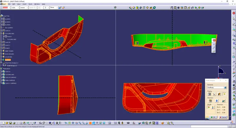
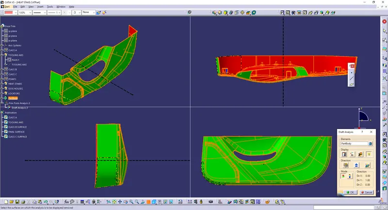
Draft Analysis is made on both sides "3
DESIGN OF DOG HOUSE
DOG HOUSE
Dog house is an engineering feature used in plastic trim design. Dog houses are used as supporting feature. Sometimes other engineering features like snaps; locators etc. are mounded on them to increase their strength. Dog houses are subjected to draft analysis to prevent breakage of the component during ejection from mould cavity. Dog house and other engineering components are built on B-surface.
DESIGN CONSIDERATION FOR PLASTICS:
1.WALL THICKNESS:
Thick sections waste material and are simply uneconomic. So solid shapes that would do the job well in wood or metal must be transformed to a 'shell' form in plastics. This is done by hollowing out or 'coring' thick parts so you are left with a component which regardless of complexity is composed essentially of relatively thin walls joined by curves, angles, corners, ribs, steps and offsets. As far as possible, all these walls should be the same thickness. Wall thickness guide range is 0.75 mm to 3 mm for reinforced materials 0.5 mm to 5 mm for unreinforced materials.
|
WALL THICKNESS(W)=0.70*(NOMINAL THICKNESS OF PLASTIC MATERIAL) |
2.CORNER RADII
Properly designed corners will make a big difference to the quality, strength and dimensional accuracy of a moulding. But there is another benefit too. Smooth curved corners help plastic flow in the mould by reducing pressure drops in the cavity and minimising flow-front break-up. Internal radii should be at least 0.5 and preferably 0.6 to 0.75 times the wall thickness.
|
CORNER RADII= (0.6-0.75) * (NOMINAL THICKNESS OF PLASTIC MATERIAL) |
3.DRAFT ANGLE:
Tooling must be cleared for easy ejection of the component, from the core cavity. In order to clear tooling certain value of draft is given to the component. Minimum of 2-3deg is provides on all plastic components.
|
DRAFT ANGLE=2-3 DEGREE |
4.FILLETS:
|
Fillet on the inner side = 0.25 * Thickness of the plastic material Fillet on the outer side = 1.25 * Thickness of the plastic material Fillet on the coring edges = 0.25 * Thickness of the plastic material Coring thickness = 0.40 * Thickness of the plastic material |
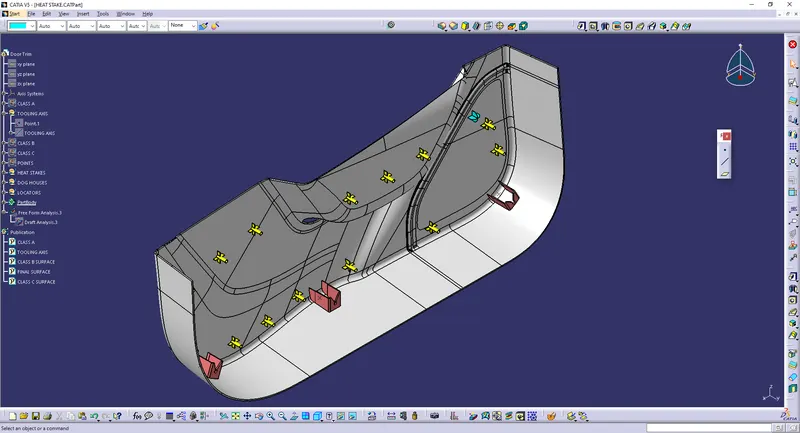
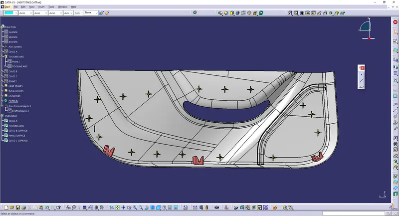
DESIGN OF HEAT STAKE
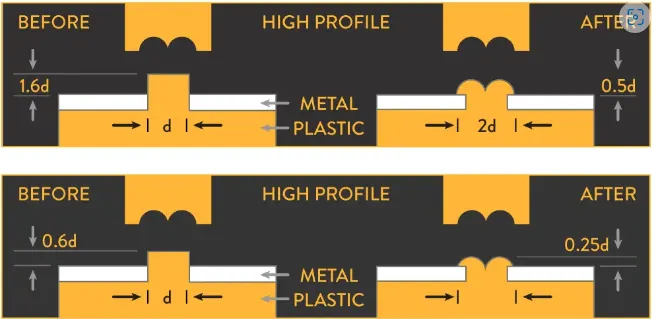
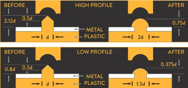
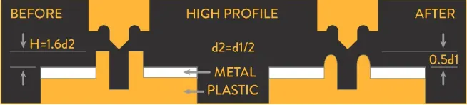
Requirements for the component design
If the heat staking process is chosen, the first step is to check whether the component is fundamentally suitable for the defined heat staking technology, i.e. whether it is optimally designed.
bdtronic offers standard tools that represent an optimal riveting as a compromise between low cycle time and maximum strength. For this purpose, there are recommendations for the different processes in the form of design guidelines, which also specify the dimensions to be taken into account for the necessary clearance area, the gap size in the joining partner, and the interference contours, so that accessibility on the components can be ensured for the tools. Special sizes and lengths are always possible.
In addition, there must be a stable, ideally flat, and supported surface underneath the rivet pin to absorb the riveting forces. To check the feasibility and reproducibility of riveting, a tolerance consideration should be made. The more complex an assembly is before riveting, the higher the assembly tolerance-related volume and position fluctuations can be.
Already in the design phase, it can be checked whether the complexity and thus the price of a production equipment can be controlled via the design. For example, it is advisable to consider the minimum distances between riveting points that are necessary per technology per riveting head or punch. In the case of product variants, the rivet positions should be kept uniform so that a rivet assembly can be used for processing the variants without tool changes. Otherwise, tool changes are possible in principle, but may require changeover times of 15 minutes or more.
DESIGN OF CONNECTORS
A door trim connector connecting structure is provided. In one embodiment of such structure, the switch unit is provided with fixed connectors, a connector securing wall provided with movable connectors is integrally formed inside the bulging portion of the door trim panel, and the screw unit secures the switch unit at the same time as engaging the fixed connectors and the movable connectors. In another embodiment of the structure, the door trim panel is provided with an insertion and connector stays, a bolt 63 penetrating a movable connector is engaged with a trim receiving plate which can be inserted through the insertion hole, the trim receiving plate can be temporarily secured to the door trim panel, the movable connector is movably supported by a holder provided with slide protrusions to be received by the guide grooves, and the trim receiving plate is inserted through the insertion hole so as to screwing the movable connector to the fixed connector after the door trim panel is attached to the door inner panel.