Week 8 - Challenge 1 - Base Bracket Design
Aim :
Create the Base Bracket Plastic component through the given Class-A surface. To begin with, the tooling axis for the given Class-A Surface should be created meeting the requirements of the draft angle and at the end perform the Draft analysis on the model.
Solution:
1.Create Tool Axis
Tool Axis: The tooling axis is basically the direction that the mold pills apart. The mold is built in two separate pieces basically. You have a cavity side and you have the core side. The core pulls apart from the cavity and that is the dyeline or the tooling direction.The draft angle, which also plays a major role in plastic component design, is decided with reference to the main tooling axis of the component
Reason to create a tool axis:
The main goal of tooling design is to create a product with high manufacturability. To do so requires a high-quality process that is:
- Simple and efficient
- Long-lasting
- Easy to operate and maintain
- Meets all specifications at the lowest possible cost
2.Draft Analysis
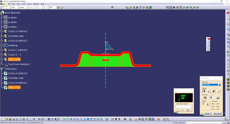
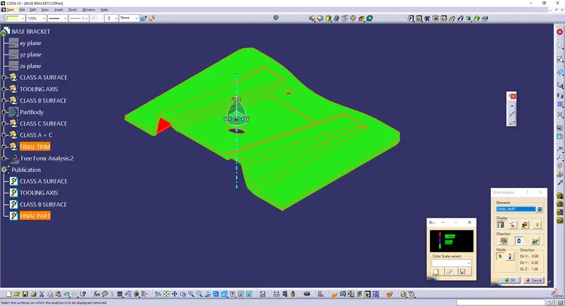
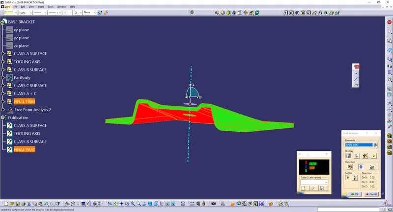
No parts can be ejected from the tool if it is having a straight 90 degree profile from its base surface. A small draft angle is provided to each and every area of the component in order to get an easy removal of the component from the tool. Draft analysis technique is used to analyze whether our part model created in cad is manufacturable based on the draft condition applied. Here the part should get easily removed from the panel dies (in case of Sheet metal part) or Mold (in case of plastic). Here we are providing a direction in which components should eject inorder to get an easy removal of components from the tool. In other words it also lets us know whether the model is having a draft angle and how much is the draft angle from the tool direction.
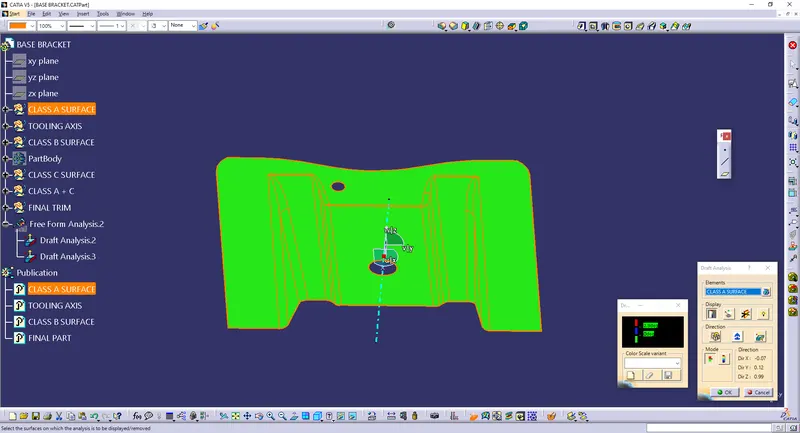
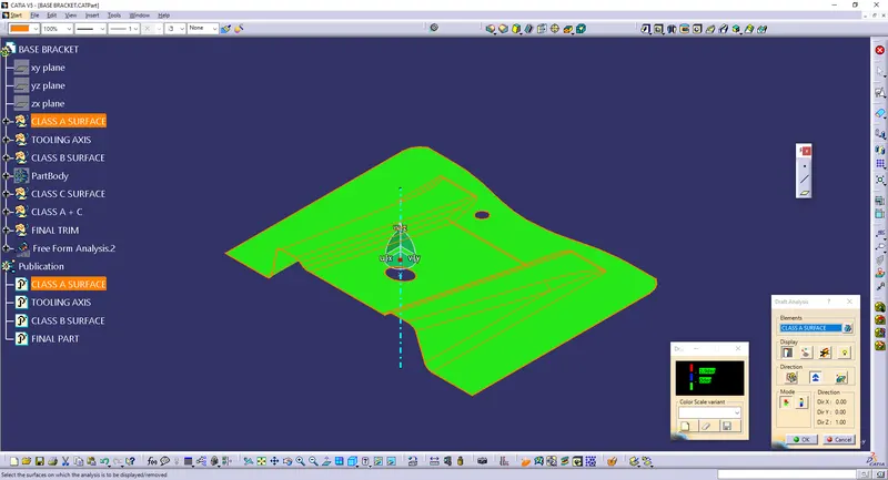
CLASS A:Class A surface refers to those surfaces which are VISIBLE and abide by the physical meaning, of a product. This classification is primarily used in the automotive and increasingly in consumer goods
CLASS A DRAFT ANALYSIS
CLASS B:Class B surfaces are the secondary surfaces that you can see sometimes, but are less important, such as the inside of your glovebox, ash tray, etc.. These must be smooth and "error-free" as well, but are not held to the standards that class A surfaces are.
CLASS B DRAFT ANALYSIS
IMAGES:
Class C
Class C surfaces are the backside surfaces that can have tool marks, flash and other imperfections without hurting appearance, function, etc..
The steps involved in creation of this project are:
1. Bringing the class A surface of the switch bezel in Catia v5 software
2. Determining the tooling axis for the switch bezel
3. Creation of class B surface
4. Creation of class C surface
5. Joining all the class A, class B and class C surfaces of the switch bezel
6. Building closed surface after joining all the surfaces
7. Draft analysis on the switch bezel
MATERIALS CAN BE USED : THERMOSET PLASTIC PPS, Torlon, and CFRPs (Carbon Fiber Reinforced Polymers) like PEEK or PAEK.
REASONS:
1.In addition to thermal stability, thermoset components provide excellent performance against corrosion and their properties are not affected by automotive fluids such as oils, fuel, engine cleaners,transmission fluid, brake fluid, and power steering fluids.
2.With a product life cycle potentially spanning up to two decades, automobiles require components that will not disfigure or disintegrate.
3.Because of excellent dimensional & chemical stability, thermoset components are able to remain durable throughout the life of the product, even when exposed to rapidly changing environments and climates.
CONCLUSION
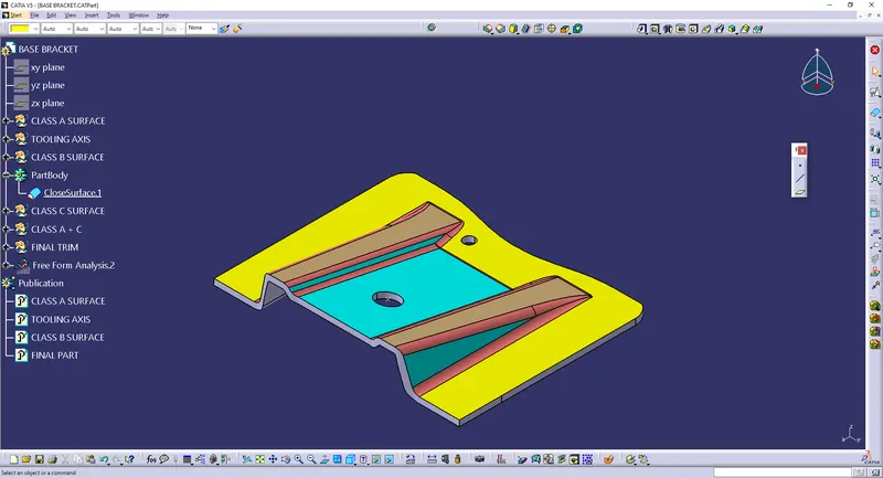
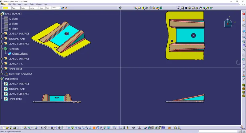
From the given input surface( class- A) The respective Class b and c surafces are created and trimmed these surfaces to form a part bodt body having 2.5 mm thick and the draft analysis also done for the final component.