Week 9 - Project 1 - Door Trim Lower with Engineering Features
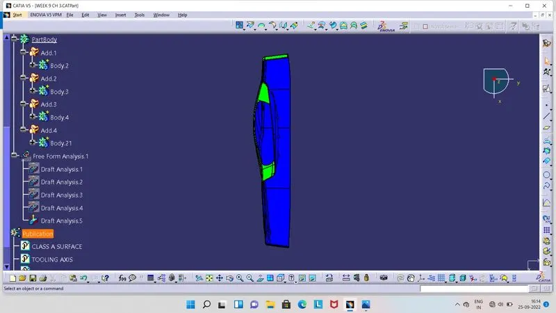
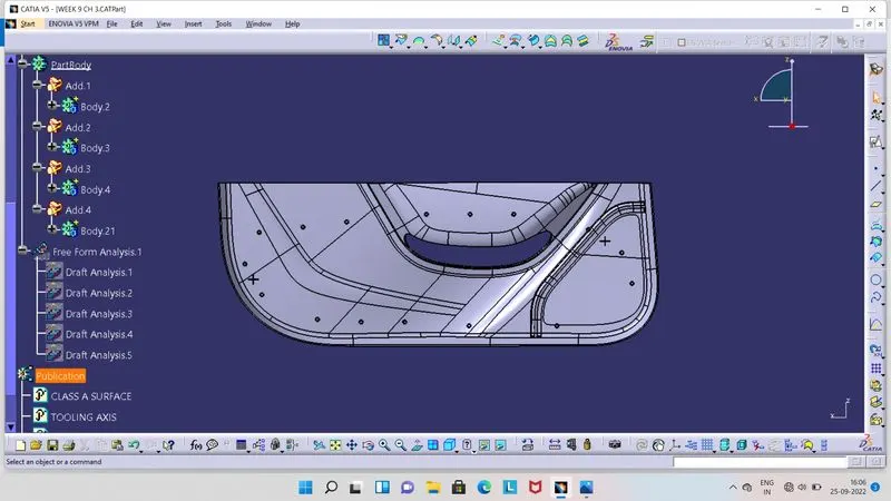
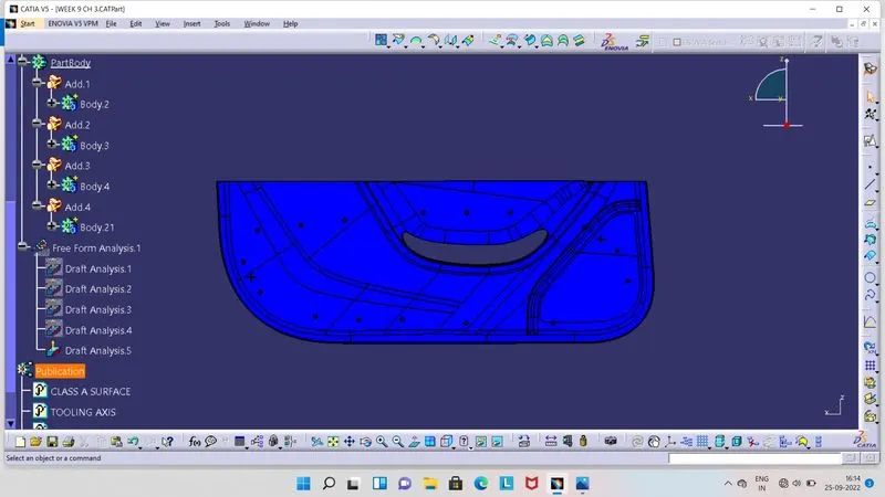
- Screenshots of Draft Analysis report for the given Class A Surface.
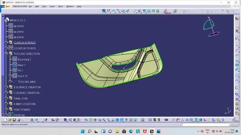
- For Draft Analysis, Tooling Axis is required. So here we have to create center point on hole surface by creating boundary there, then have to fill that area.
- From that center point, we have to create a normal line through that point in Y direction.
- We choosen Y direction as in this direction we will able to see all parts of the component.
- So in this way we get Tooling Axis in Y direction.
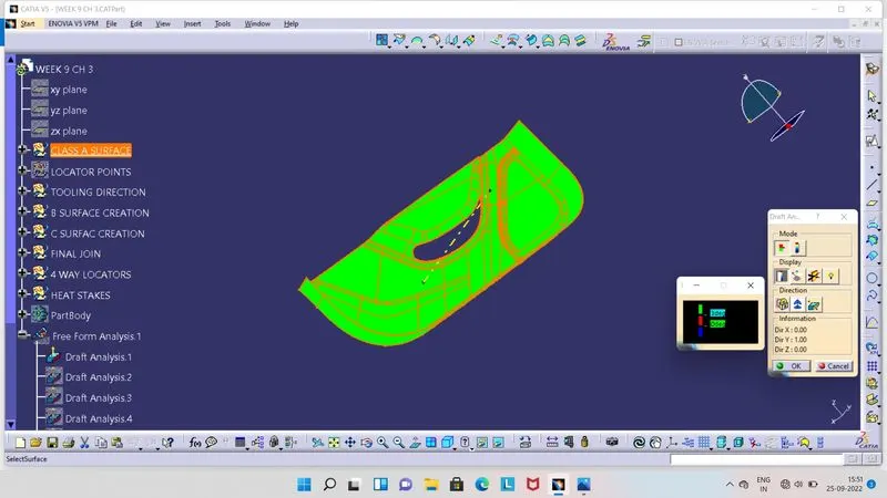
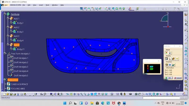
- Once we get Tooling Axis, we can go for Draft Analysis. Click on Feature Draft Analysis tool and open it.
- Ensure that our component in the material view mode. As we open Draft Analysis tool, we can able to see 2 boxes as shown in above image.
- Click on compass, so compass will be seen to screen. Align this compass with Tooling Axis and click lock symbol and then on Class A Surface.
- So surface get colour on it.
- Green colour indicates that, draft angle is above the 3 degrees.
- Red colour indicates that, draft angle is between 0 to 3 degrees.
- Blue colour indicates that, draft angle is below 0 degrees or negative.
- Screenshot of Draft Analysis for Plastic Component without Locators and Heat Steakes.
- Class B Surface :
- Its a offset surface of Class A Surface.
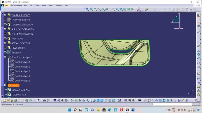
- Class C Surface :
- Its joining surface of Class A and B Surfaces.
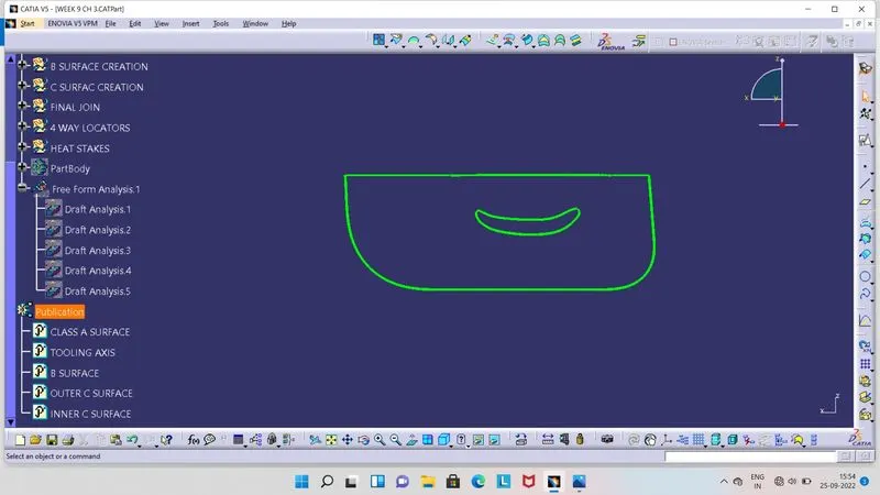
- Class A, B and C joining surfaces.
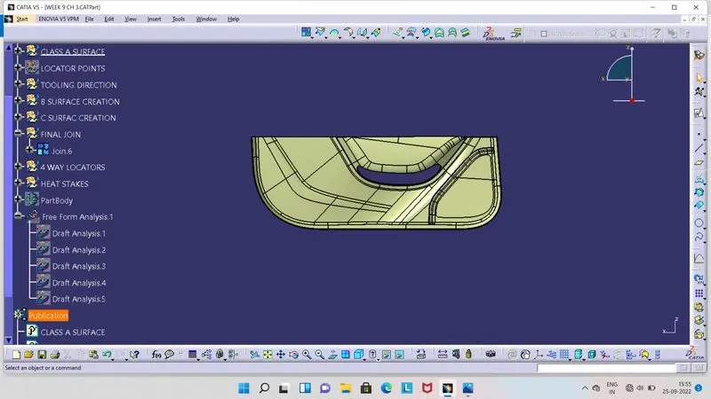
- Final Plastic Component without locators and heat stackes.
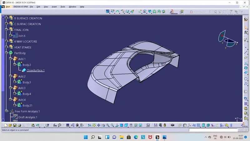
- Draft Analysis of Plastic Component :
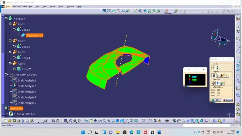
- Click on Feature Draft Analysis tool and open it.
- Ensure that our component in the material view mode. As we open Draft Analysis tool, we can able to see 2 boxes as shown in above image.
- Click on compass, so compass will be seen to screen. Align this compass with Tooling Axis and click lock symbol and then on plastic component.
- So component get colour on it.
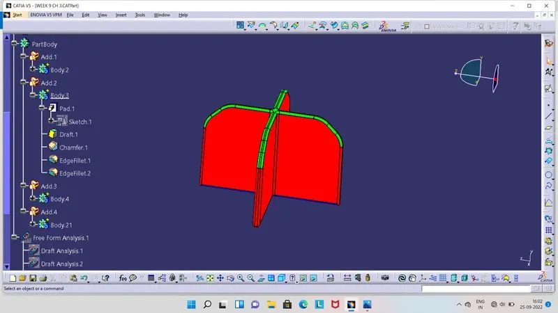
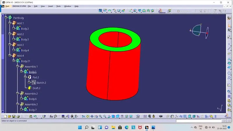
- Green colour indicates that, draft angle is above the 3 degrees.
- Red colour indicates that, draft angle is between 0 to 3 degrees.
- Blue colour indicates that, draft angle is below 0 degrees or negative.
- 4 Way Locator :
- Its a component use to positioning the attachment component on the main component.
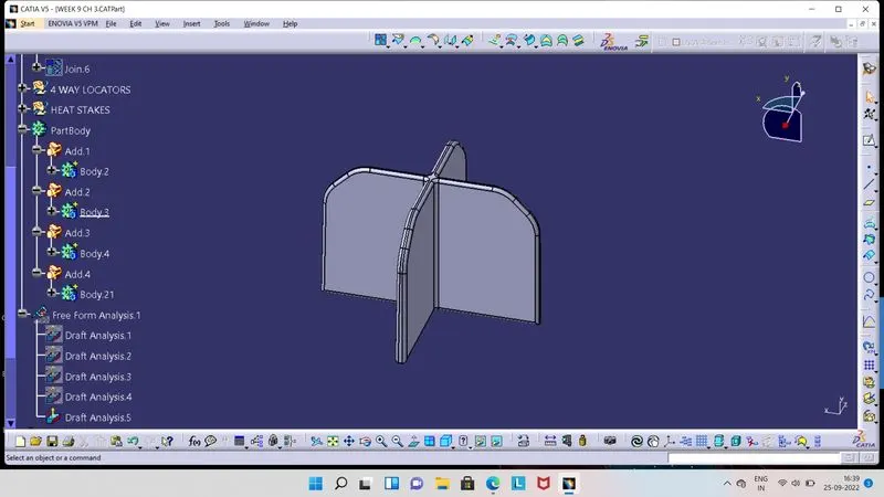
- For design this Locator, we have created 2 crossd lines with 20 mm. Its like rib construction.
- So, we have given thickness for it is 1 mm by using relation of 0.4 × thickness of main component.
- Height, we have given as 12.5 mm by using relation of 5 × Thickness of component.
- We have given Draft of 0.5 per side of Locator.
- At 4 corner edges of Locator we have given 3 mm chamfer.
- Then 0.3 mm of Fillet radius at all side edges of Locators and 3 mm on upper edges.
- In this way, we have restricted 11 degrees of freedom for locators and only one translation degree of freedom we have kept for positioning the locator on main component.
- Draft Analysis of Locator :
- Heat Stake :
- For joining the 2 dissimilar or similar materials with each other by means of melting the created portion of attachement component on the main component.
- There are many advantages of it, like reduce machinery cost, Time saving and economical.
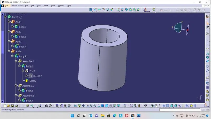
- For designing this Heat Stake, we have created circle with 5 mm diameter.
- By using relation of thickness of wall, 0.6 × Main component thickness. So we get 1.5 mm, then by giving wall thickness per side, we created of 8 mm diameter circle and then give pad to it.
- Its construction is like a Screw Boss, so for height we used relation of Diameter to Height ratio of 3:1, but in this way height of Heat Stake we get as 15 mm, which goes beyond the height of Locator. So we have given 5 mm less height to Heat Stake as compare to the Locator for do fixation after the positioning. So here we have given height to Heat Stake is 7.5 mm.
- Then we have given 0.5 degrees of draft inside and outside of this heat stake.
- Draft Analysis of Heat Stake :
- Final Plastic Component with Locators and Heat Stakes.
- Draft Analysis Of Final Plastic Component :
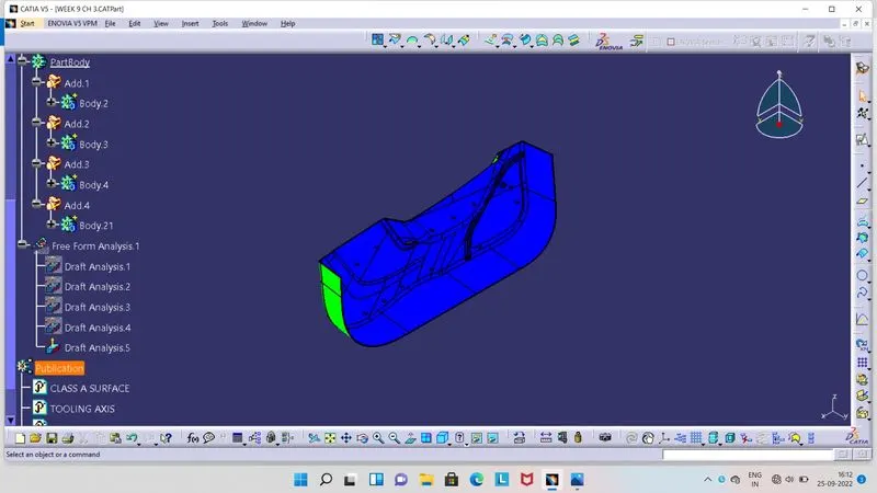
- Screenshots of the completed design in various orientations.
- Isometric View :
- Front View :
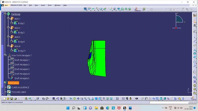
- Side View :
- Top View :