Week 9 - Project 1 - Door Trim Lower with Engineering Features
Report
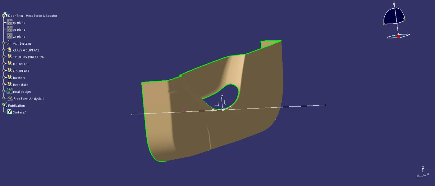
Step 1: First created the centre gravity point and then created the axis for the moving the mould moving axis. command toolis used for draw a line that is the tooling axis.
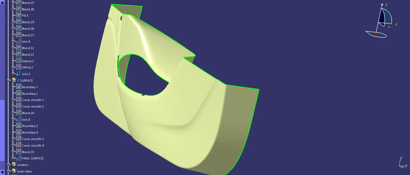
Step 2: created the extract surface for the using extract tool and then offsted by the surface in the 2.5 mm.
Step 3: Then created the offsetted surface that will having the some pateches of the surface and using the blend and filling tool and make it for the closed surface.
Step 4: And then the join the patches closed surface.
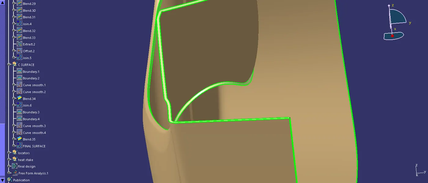
Step 5: In the surface A and surafce B is created the boundary edge give the command of smooth curve and then using the blend command to create the c surface and using the join command to created the closedd surface.
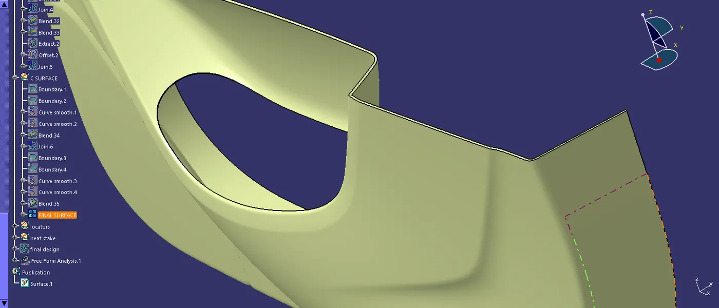
Step 6: And then move to part body created the closed solid surface.
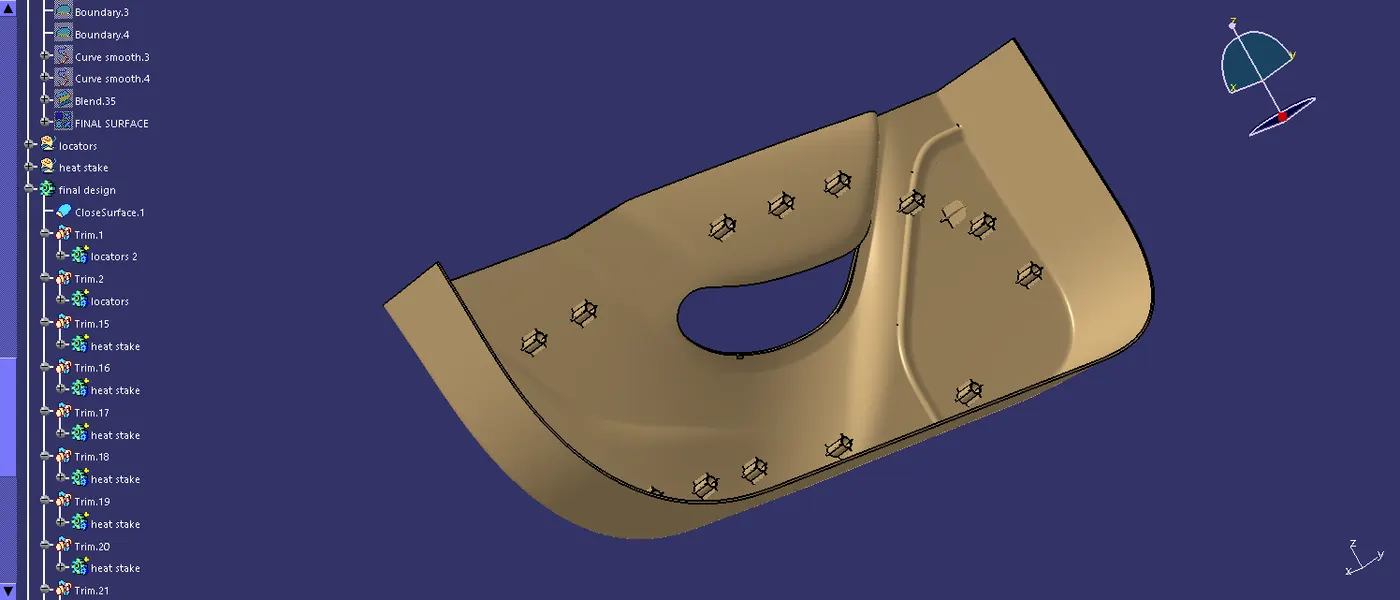
step 7: Located is created the position sketch and for the required dimension and move to part body to pad the line with using the thick and nuetral fiber for centering the solid .
Step 8: And then using the draft tool draft the locator in 0.5 deg of the draft, then the fillet is done and using the union trim command then using the transulation of point to point command. transfer the locator in other place.
Step 9: Thent the give point of the heat steak to using the sketch tool make a sketch of the heat steak and then using the pad command and pad the sketch after that of the support rib is used to give the strength of the heat steak.
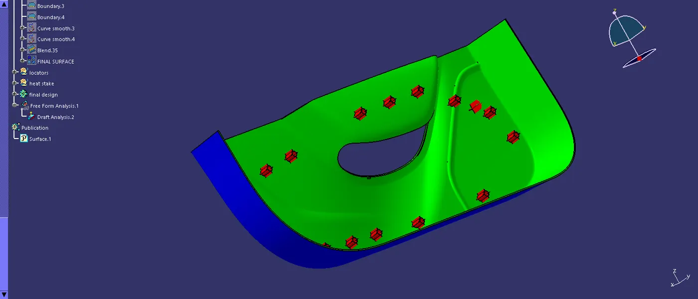
Step 10: Using the transulation tool make a copy of the all point and then using union trim command and make it for the solid surface joining
Step 11: In using the part body of make the draft analsis for the making mould in based of the draft , so its showing the green colour of the surface is the 2 deg and blue is nuteral then red is zero deg.
Step 12: make it for the publication for the surface is easy to handle in work bench.