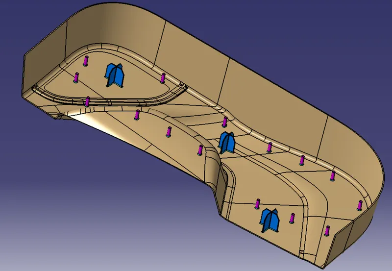
Week 9 - Project 1 - Door Trim Lower with Engineering Features
Tooling Axis
The tooling axis is used to determine the direction of core and cavity movements (Closing and opening).
- A point is created on a flat surface, and an axis system is created about the point. Based on the axis system a dumb tool axis is made.
- The intersection sketch is created to capture the surface with a low draft angle.
- The lines are created about lines with low draft angles in intersection sketches.
- These lines are bisected to give a final line which is considered the tooling axis.
Draft Analysis
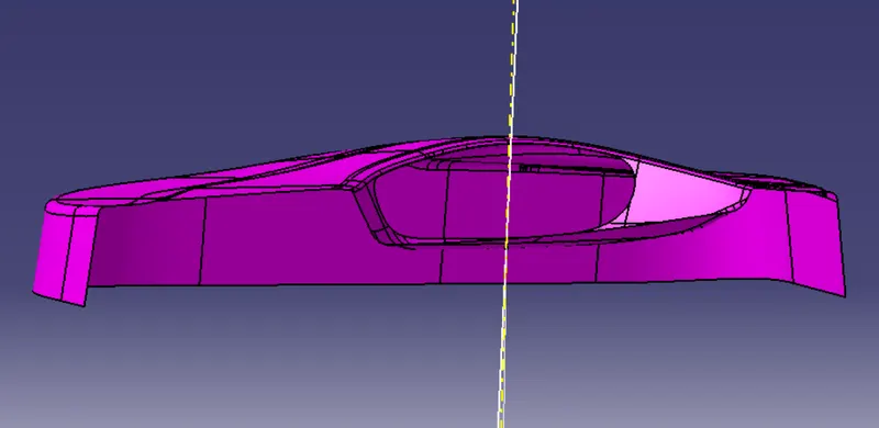
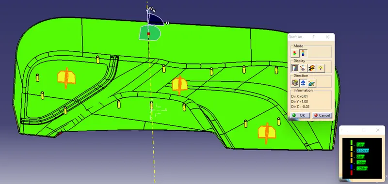
The draft analysis is conducted to make sure that all the surfaces form a minimum draft angle along the tool axis.
- The material mode is selected, and the tooling direction is given.
- The surface to be analyzed is selected.
- The visual inspection is conducted to make sure that all the surface maintains the minimum tooling axis, if not, the tooling axis is tilted accordingly.
Locators
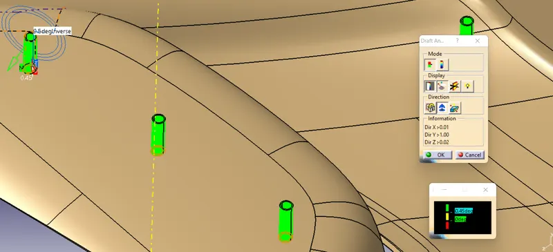
Heat Stakes
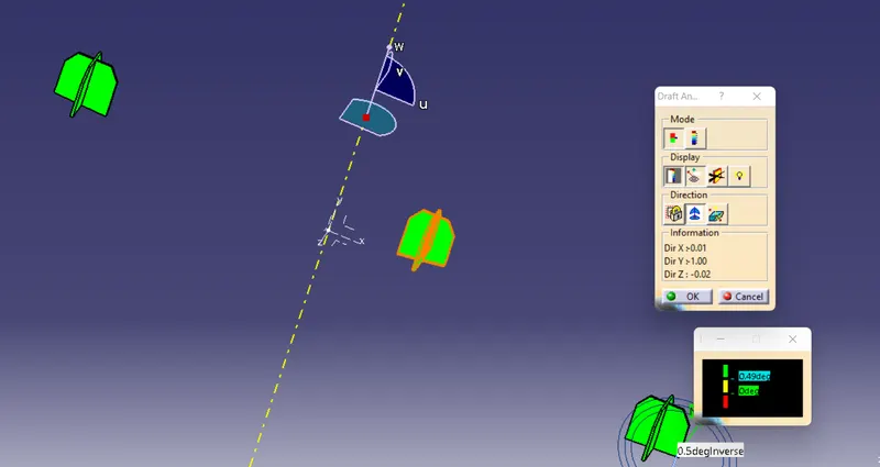
Model
Standard Views
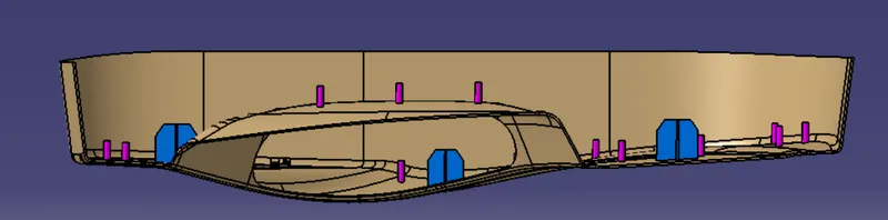
Front View
Side View
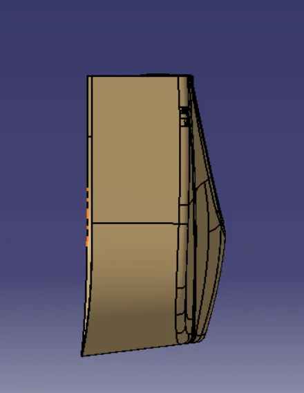
Top view
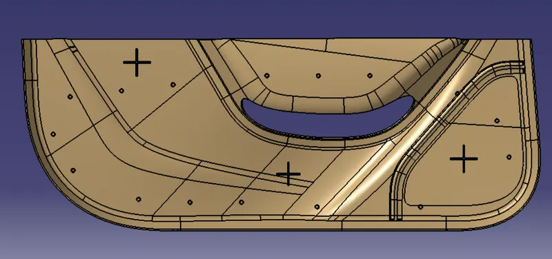
Isometric View