Week 9 - Project 1 - Door Applique Design with Engineering Features
Aim: To perform the Draft analysis on the door applique.
Procedure:
Before performing the draft analysis we need to inspect the A surface for gaps by using the boundary command after joining the different applique forming styling surfaces. If the gaps exceed a minimum merging distance of 0.003mm, we need to look into the gaps and try to fix the surface.
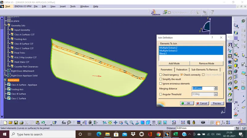
Once a continuous surface of the A surface is formed we need to create a tooling axis.
Tooling axis creation:
1. To create our tooling axis, we need to inspect the part normally from the X Y and Z directions. We observe that the most amount of area lies in the XZ plane. There does not seem to be any bending angles on the A surface that would be parallel to the Y-axis but we can confirm this after performing our draft analysis. Creating a tooling axis from any other axis is not recommended as this would call the need for side cores.
3. Now we will create a point from our Class A surface.
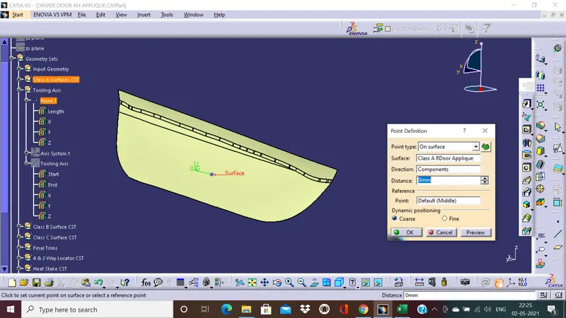
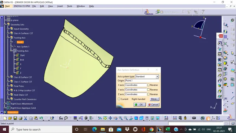
4.Next we shall create a new axis system using the point we created as the origin of the axis system. We must make sure the current check box is unchecked.
5.We can estimate a new tooling axis by creating a new line in the Y direction and make it pass through the surface center point we created.
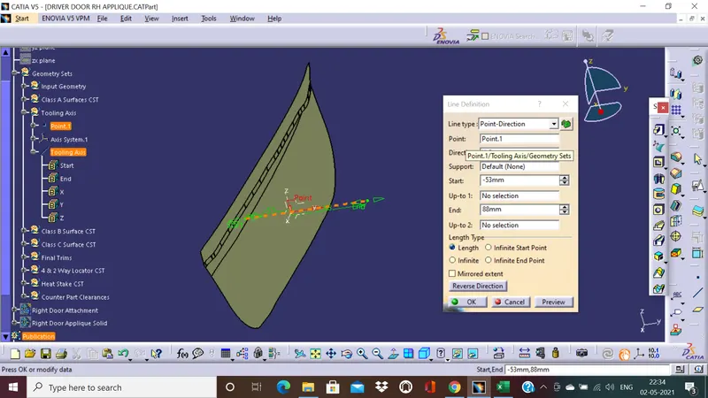
6. Using this estimate axis we can perform a draft analysis. From the analysis on the A-surface, we can go ahead with the tooling axis in the Y direction as all faces are clearing the minimum desired draft angle of 3-degrees.
Observations:
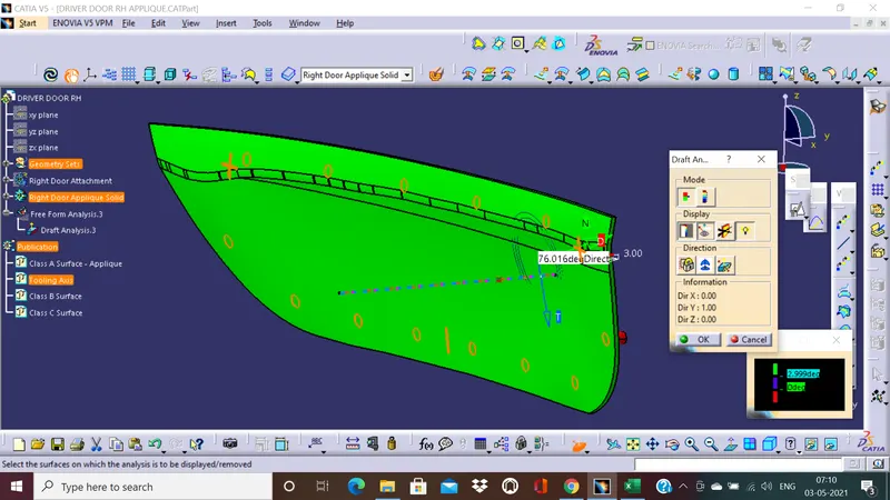
A-surface Draft analysis screenshots:
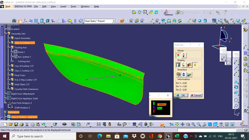
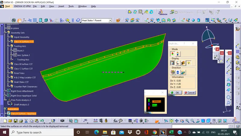
Color code representation of the A-Surface with the tooling axis:
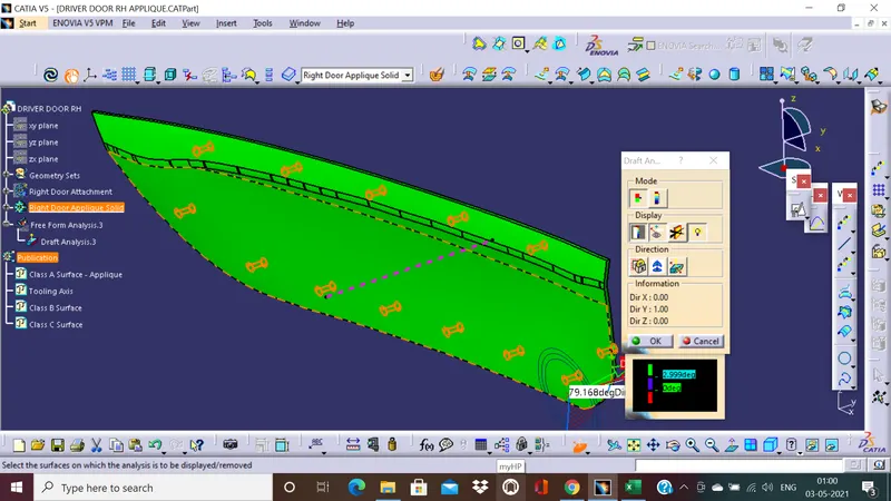
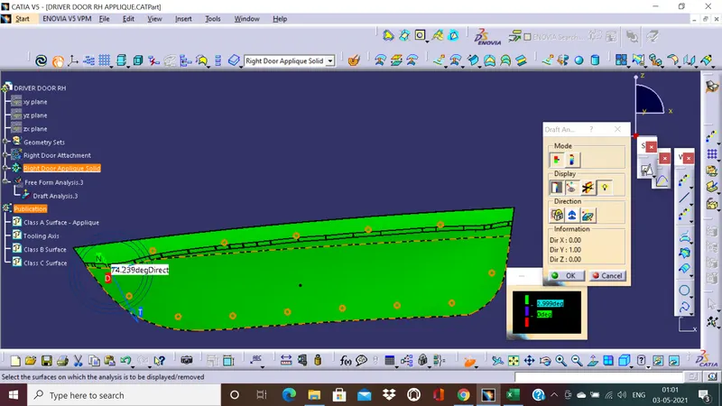
Green: Greater than 2.999-degree draft angle
Blue:0 to 2.999-degree draft angles
Red: Less than 0-degree draft angles
Model Draft Analysis:
The class-A side of the component's draft regions is shown below with the same color to draft angle ranges as before. The draft angles on the A-surface side are greater than 2.999-degrees from the tooling axis.
Now, let's see the draft angles on the C-surface
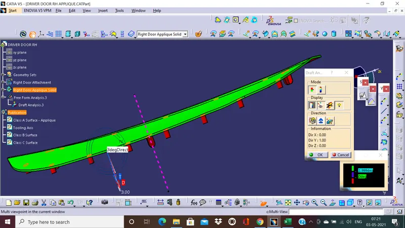
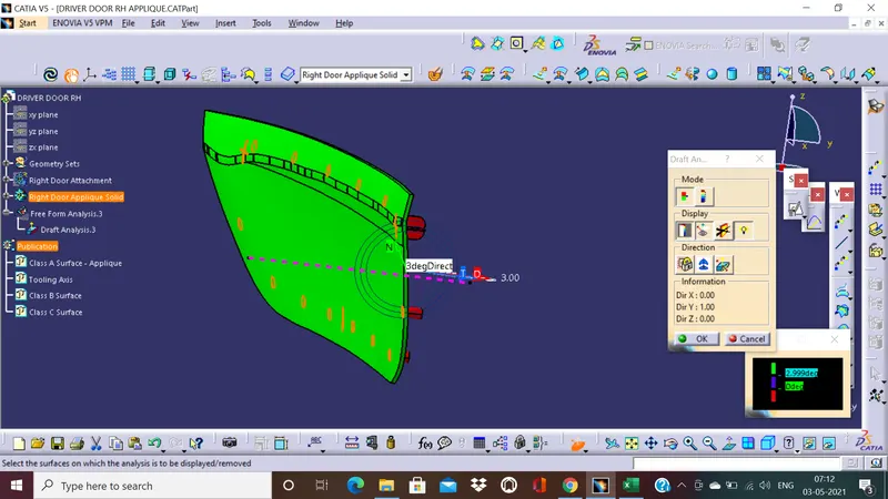
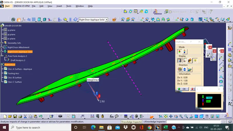
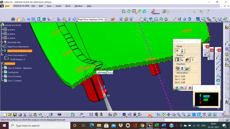
The C surface has an overall draft angle of 3degrees with the least draft angle falling to 2.95 degrees in a region. This is an acceptable draft angle for a good quality surface finish from the component.
Finally, we will observe the draft angles on the B-Surface now.
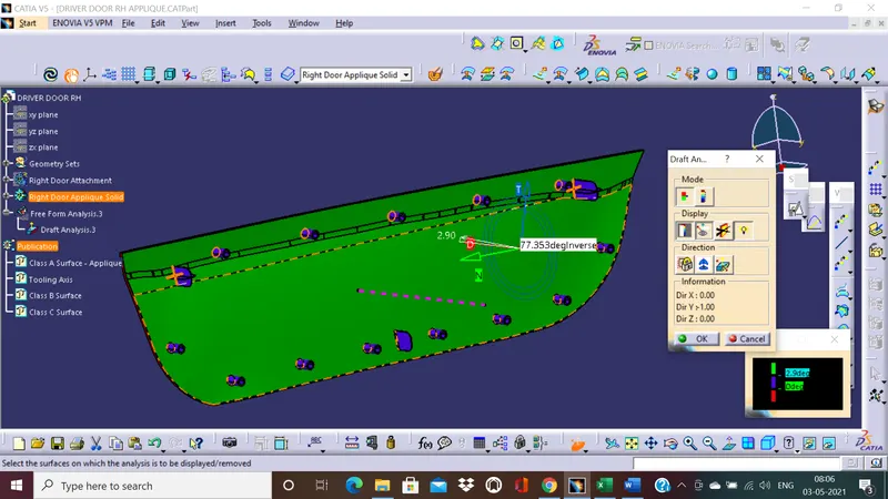
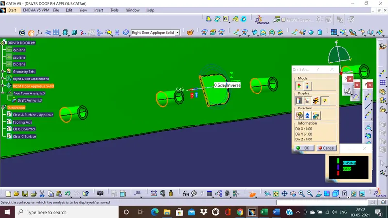
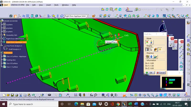
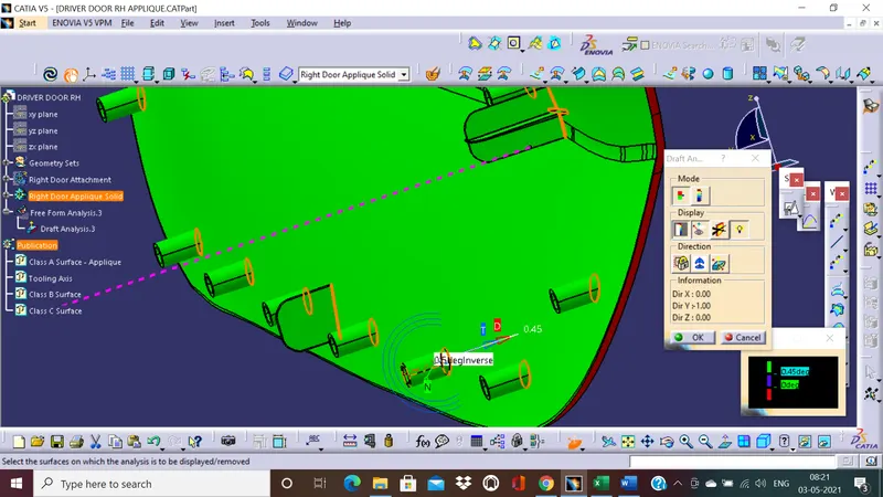
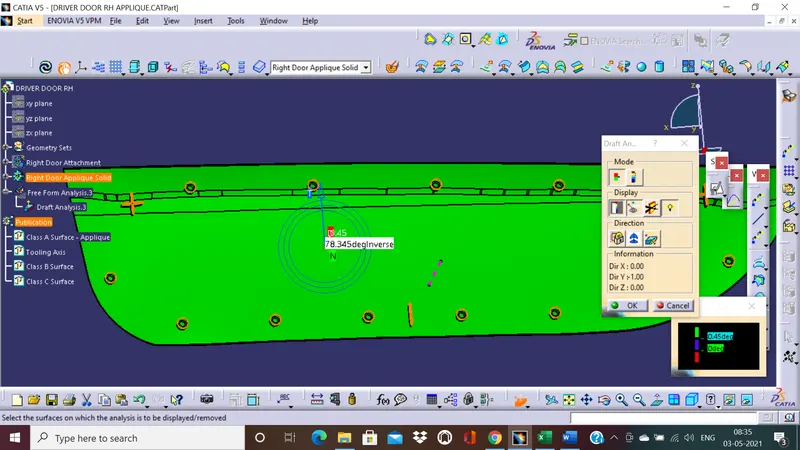
We observe two colored regions in green and blue on the B-surface. The green-colored region is the base B-surface whereas the blue region is the region comprising the engineering features such as the 2 and 4-way locators and also the heat stakes.
We will use a different color code and focus on the engineering features. The new color code region to the draft angle from the tooling axis is given below.
Green: greater than 0.45-degrees
Blue: 0 to 0.449-degrees
Red: negative draft angles
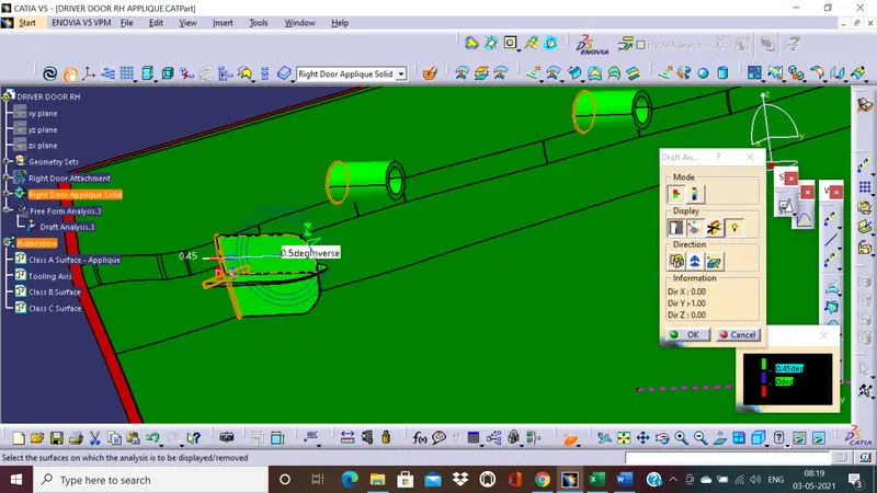
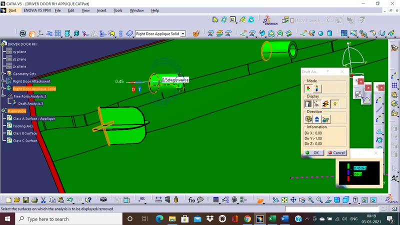
Conclusion:
From the draft analysis screenshots, the right-hand door applique component is designed according to molding guidelines. The A and C surfaces are falling in a minimum draft angle range of 3 and 2.9 degrees from the tooling axis. The primary surface on the B-surface side also has the same range, however, since the engineering features do not need an excellent surface finish a minimum draft angle of 0.5-degrees is maintained on the locators and on the heat stakes as well.
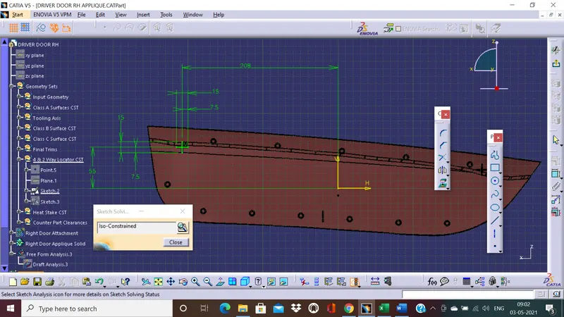
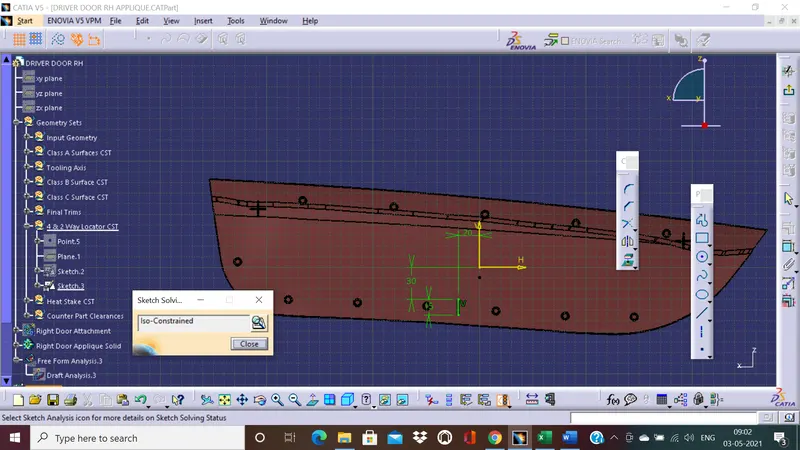
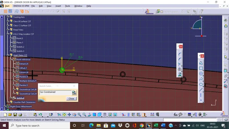
Iso-constrained sketches:
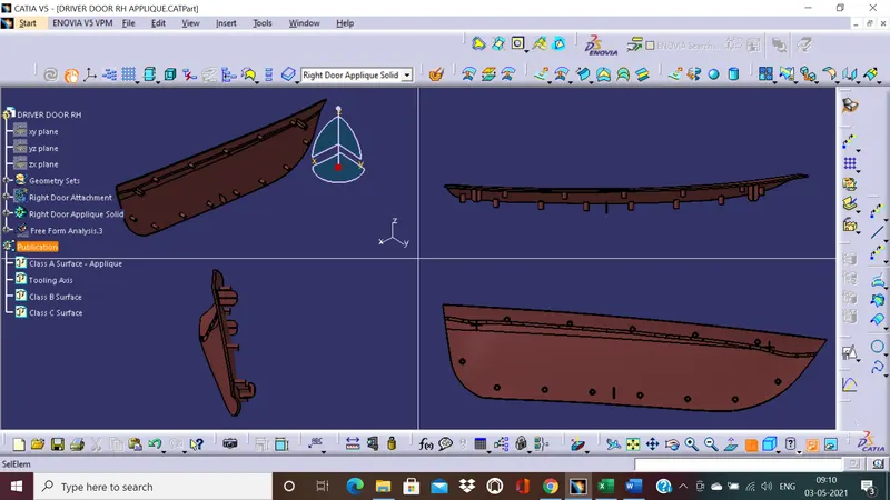
Quadrant views:
Q1:Top view
Q2:Iso-metric view
Q3:Front view
Q4:Side view
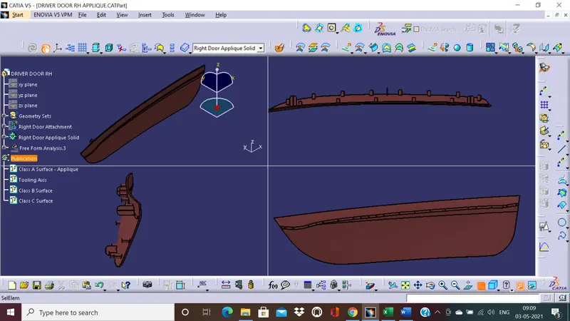
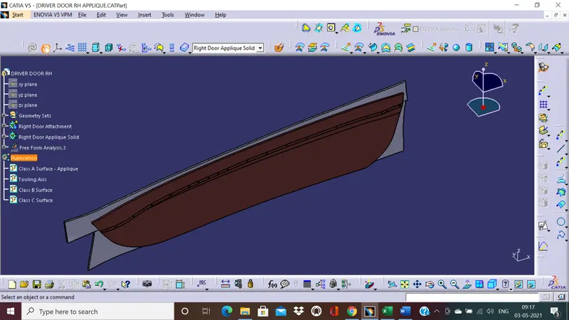
Q1:Bottom view
Q2:Iso-metric view
Q3:back view
Q4:Side view
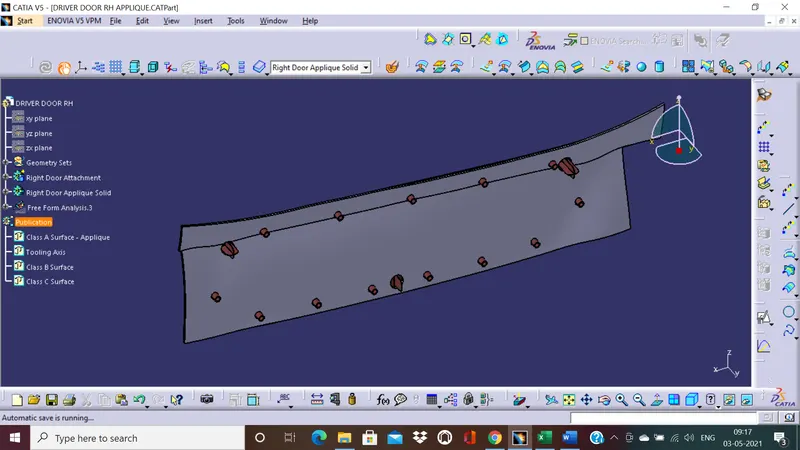
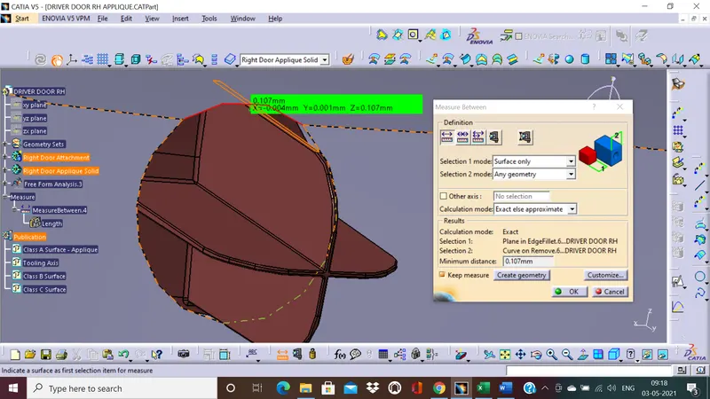
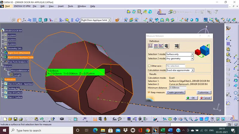
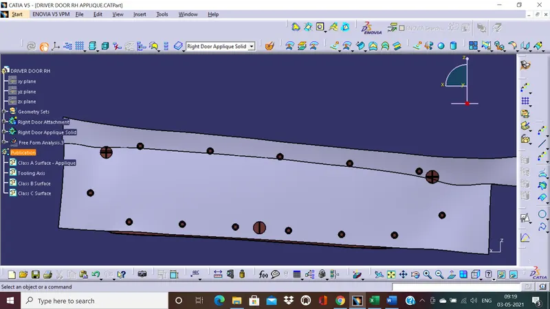
Clearance hole images:
Please see the attached file for the cat part. Thank you.