Week 9 - Project 1 - Door Applique Design with Engineering Features
OPERATION : Design of door applique with engineering features
PLATFORM USED : CATIA V5
HEAT STAKING :
In manufacturing products with thermoplastic components , it is often necessary to join a thermoplastic to a part of dissimilar material,whether it be metal, adissimilar plastic ,or material. this technical information sheet provides design guidelines ,configurations and technique for successful thermal (heat) staking.
GENERAL DISCRIPTION:
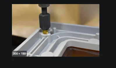
Thermal staking is a assembly method trhat uses the controlled melting and refroming of a plastic stud or boss to capture or load another plastic or metal component of a assembly in place . th eplastic stud protudes through a hole in the component to be locked in place. The heated thermal tip contacts the top of the stud ,which melts and fills the volume of the tip cavity to produce a head ,locking the component in place.
Introduction : The progressive melting of plastic under continuous forms the head.When staking, the right combination of heat and pressure for the application is critical
Advantages of staking :
- Simplification of machinery
- reduced cost of machinery
- Multiple fasting points
- Allow higher density of welds when compared to hot air cold form or ultrasonic welding
3-2-1 Principle :
In the automotive tooling industry you will hardly get any designer who does not know 3-2-1 principle
If the any part e.g steel block to be machined using milling machine, the first thing the milling operator will think how will he going to hold the part.
Operator will use the various clamp to hold the job to withstand the cutting forces .
Ideally 3-2-1 principle is used to locate the job .
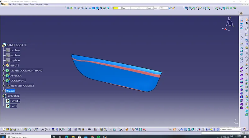
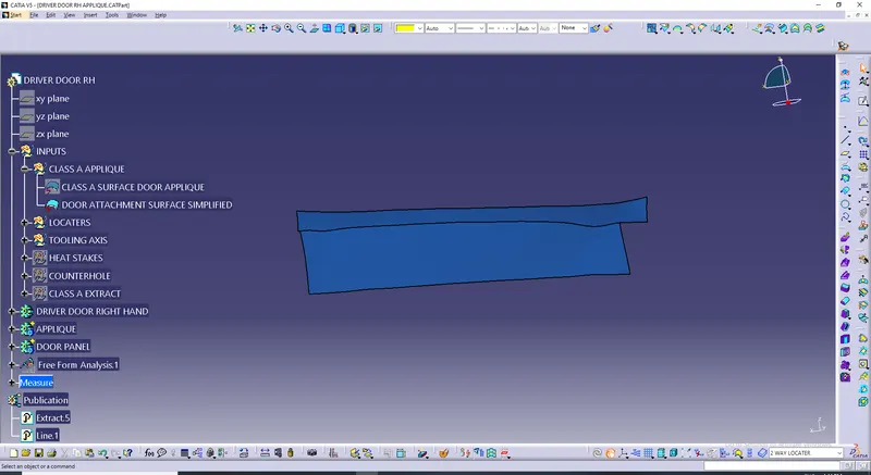
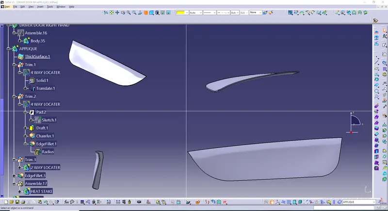
Any part which has to be fixed during welding or during machining process has to be fixed.
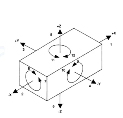
Every object is having 12 degress of freedom
1.Translational movement along x-axis
2.Translational movement along y -axis
3.Translational movement along z- axis
4.Rotational movement along x-axis
5.Rotational movement along y-axis
6.Rotational movement along z-axis
- Material Considerations. ...
- Radius. ...
- Wall Thickness. ...
- Gate Location. ...
- Draft. ...
- Inclusion of Ribs. ...
- Mold Shrinkage. ...
- Special Features.
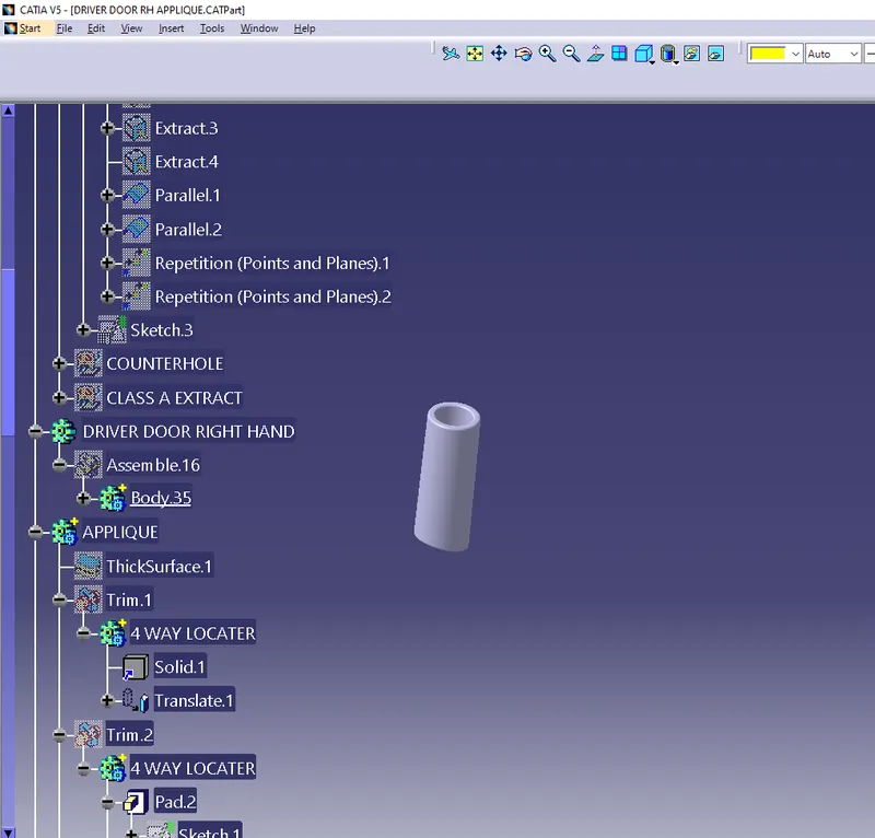
Design of 4 way locater
4-way mean you prevent movement at 2 axis (+X, -X, +Y and -Y) on the plane. Generally you have cylindrical pin on the fixture and circular hole at workpiece part. 2-way mean you prevent movement only at 1 axis on the plane. And generally you have cylindrical pin on the fixture and slot hole at workpiece part.
LOCATING METHODS AND DEVICES Locators are those parts of a jigs or fixture which helps a work piece to seat in proper position in it . Depend upon type of work, locators are designed .
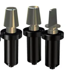
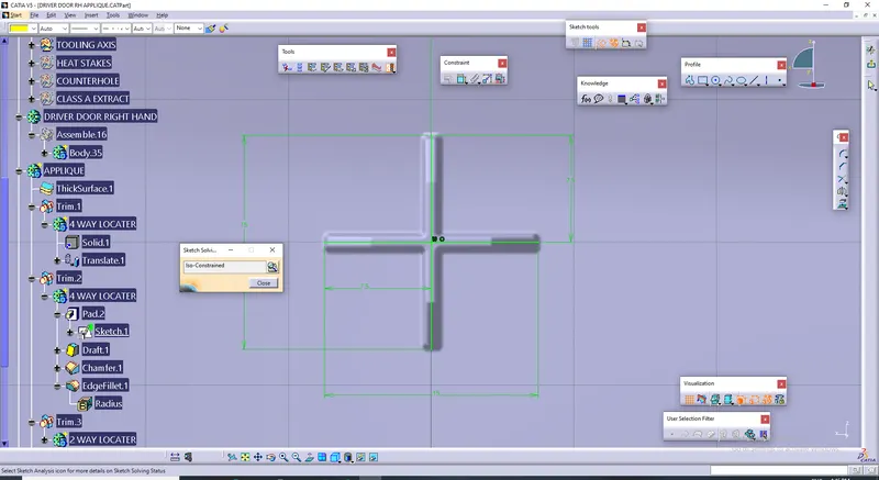
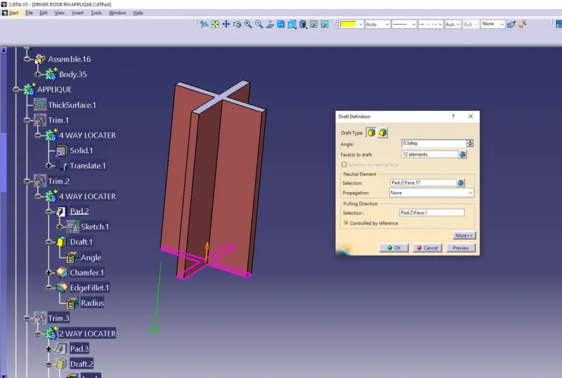
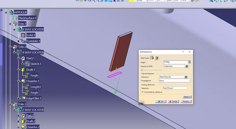
The radius eliminates a sharp corner and stress concentration. Flow and cooling are also improved. Fillet radius at the base of ribs should be between 0.25 and 0.4 times the nominal wall thicknesses of the part. Draft angle for ribs: Draft angle design is an important factor when designing plastic parts.
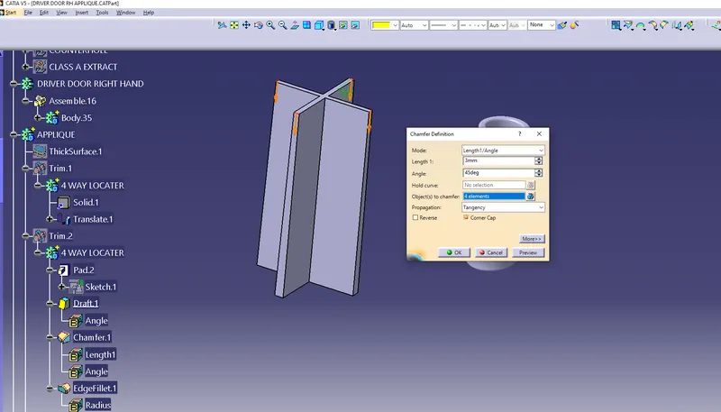
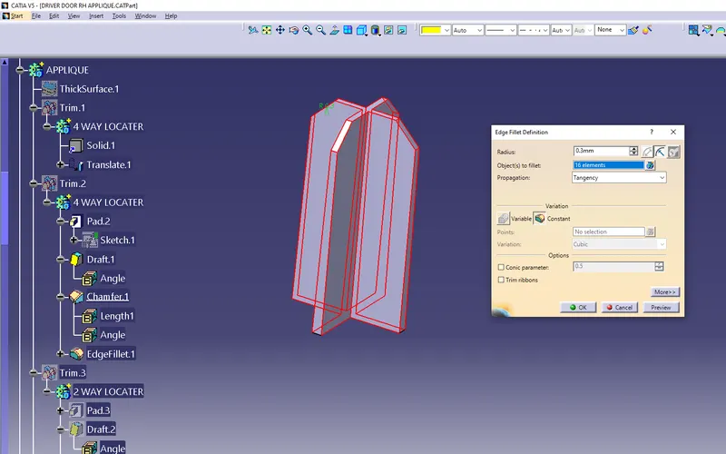
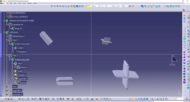
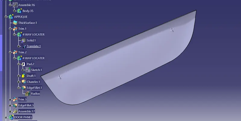
- TRANSLATING the 4 way locater
-
Translating Geometry
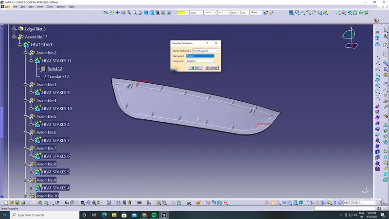
- Click Translate . The Translate Definition dialog box appears as well as the Tools Palette. For further information about the Tools Palette, refer to Selecting Using Selection Traps in the CATIA Infrastructure User's Guide.
- Select the Element to be translated.
- Select the Vector Definition .
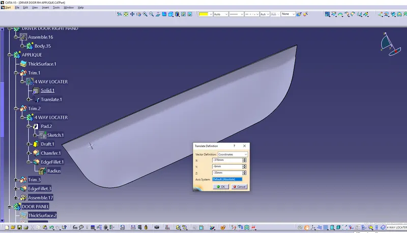
- Design of 2 way locater
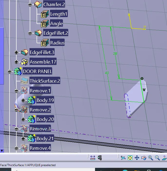
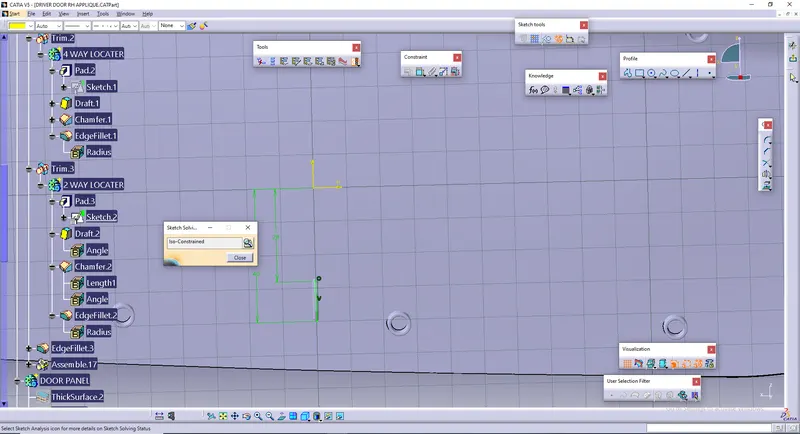
A 2-way locating pin restricts motion along 1 axis (or 2 degrees of Freedom), like a round pin in a slot. Likewise, a 4-way pin restricts 4 degrees of freedom along 2 axes. A round locating pin located concentrically in a hole is a common application of a 4-way pin, and helps to further secure the piece.
- Material Considerations. ...
- Radius. ...
- Wall Thickness. ...
- Gate Location. ...
- Draft. ...
- Inclusion of Ribs. ...
- Mold Shrinkage. ...
- Special Features.
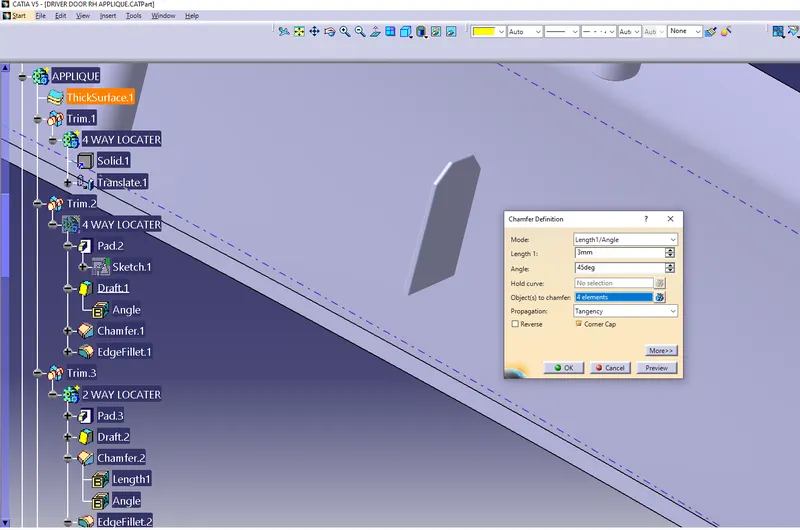
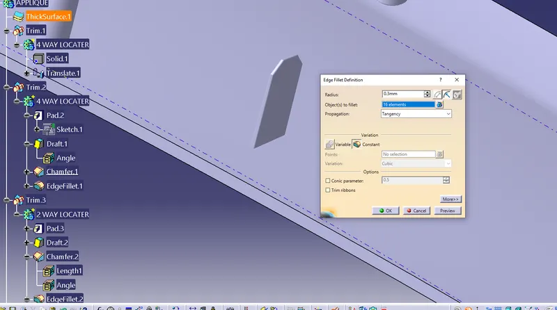
- Design of heat staking in cad model
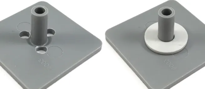
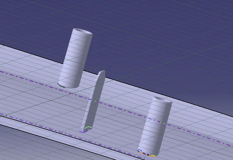
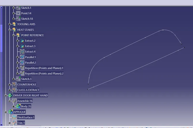
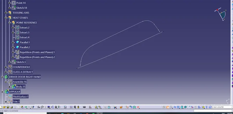
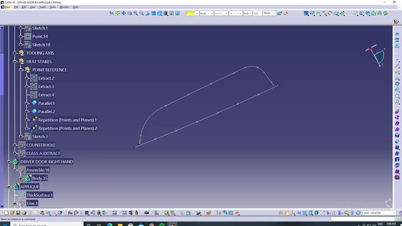
Extracting the class A boundary to form heat stakes in several places
- Select the Point to Point option in the Translate Options field. ...
- Define the two points by clicking on a surface. ...
- The Offset Distance field is not relevant for this option.
- To rotate the element you just positioned, select the Rotation Axis field in the Translate Objects dialog box and define an axis.
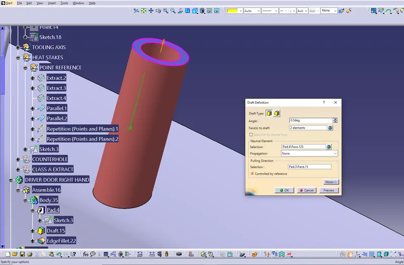
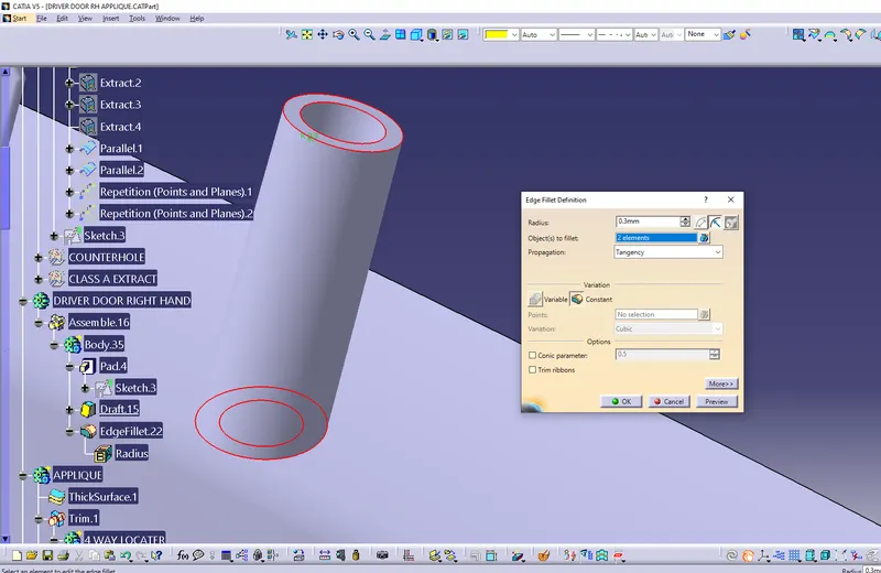
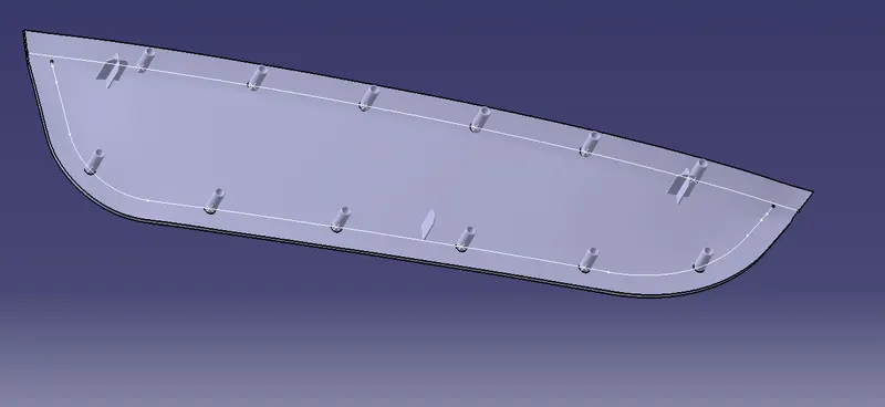
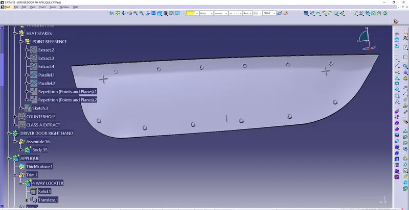
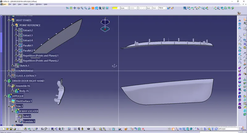
Final Allique part design
MEASURMENT BETWEEN COUNTERHOLE CLEARANCE
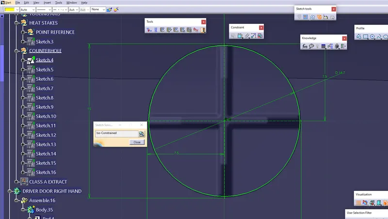
COUNTERHOLE CLEARANCE FOR 4-WAY LOCATER
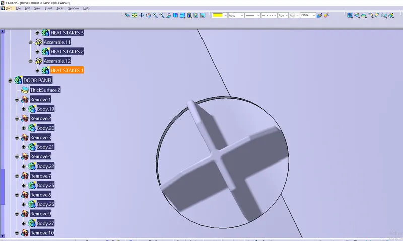
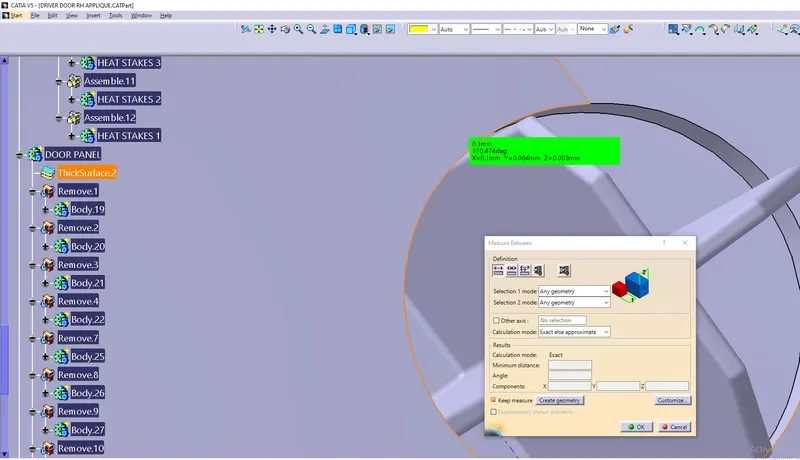
COUNTERHOLE CLEARANCE FOR HEAT STAKES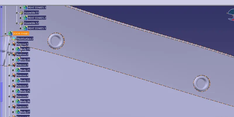
COUNTERHOLE CLEARANCE FOR 2 WAY LOCATER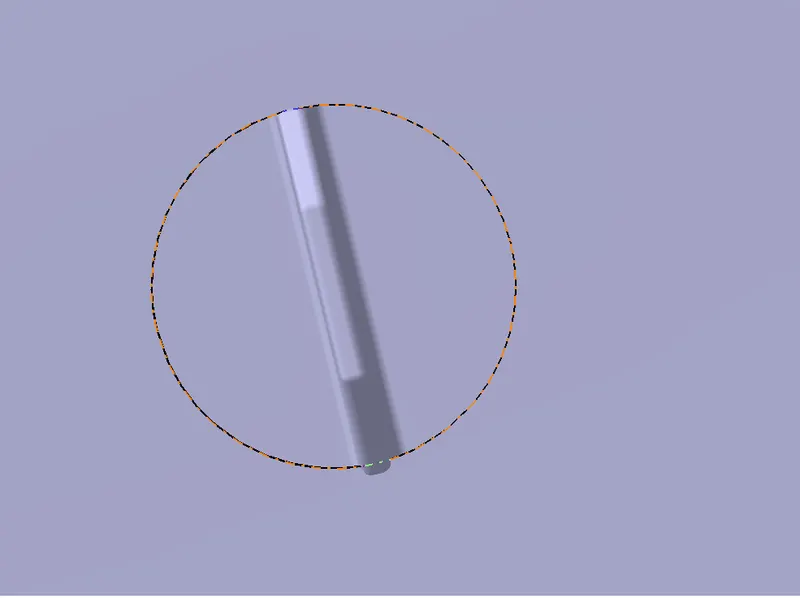
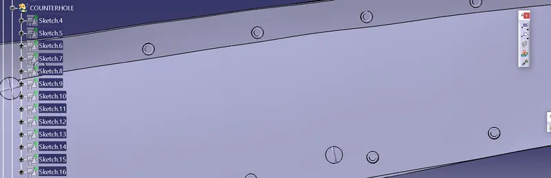
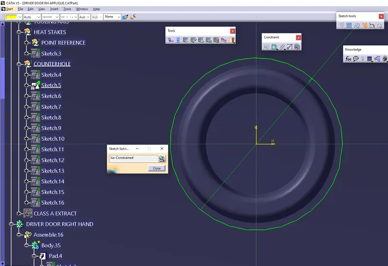
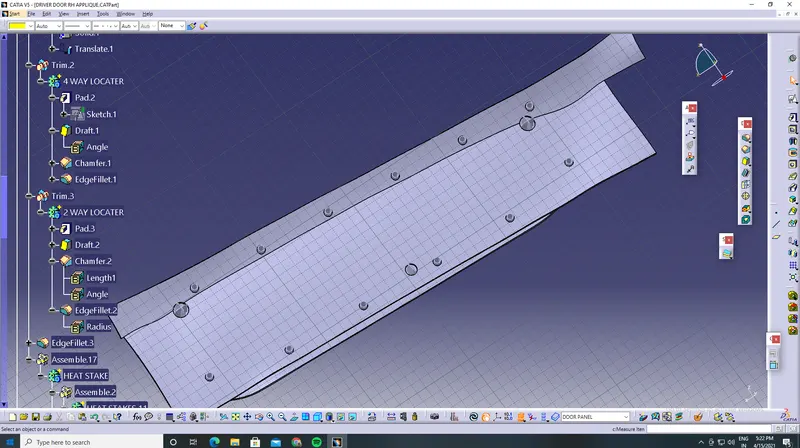
FINAL CLEARANCE PART
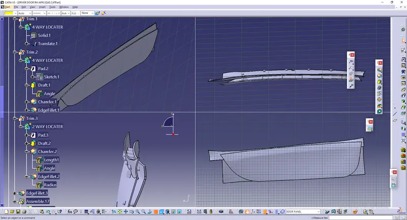
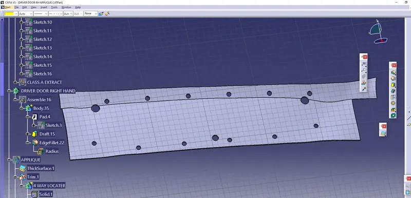
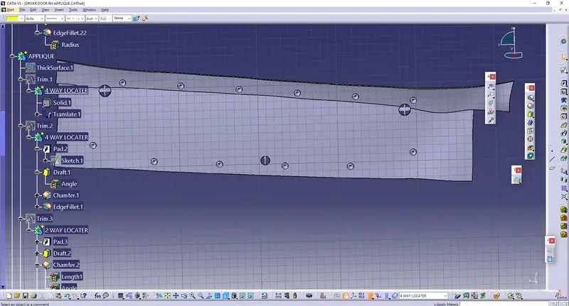
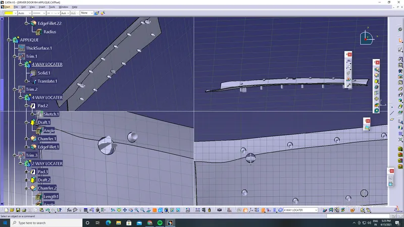
FINAL DESIGN 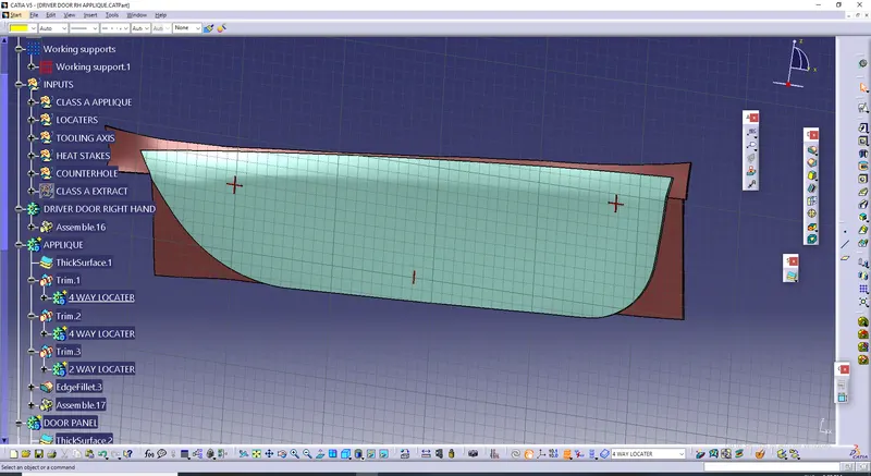 TREE STRUCTURE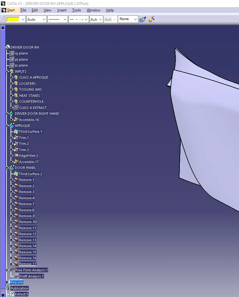
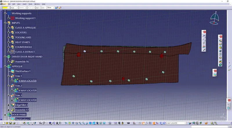
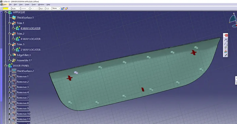
TOOLING DIRECTION FOR THE COMPONENT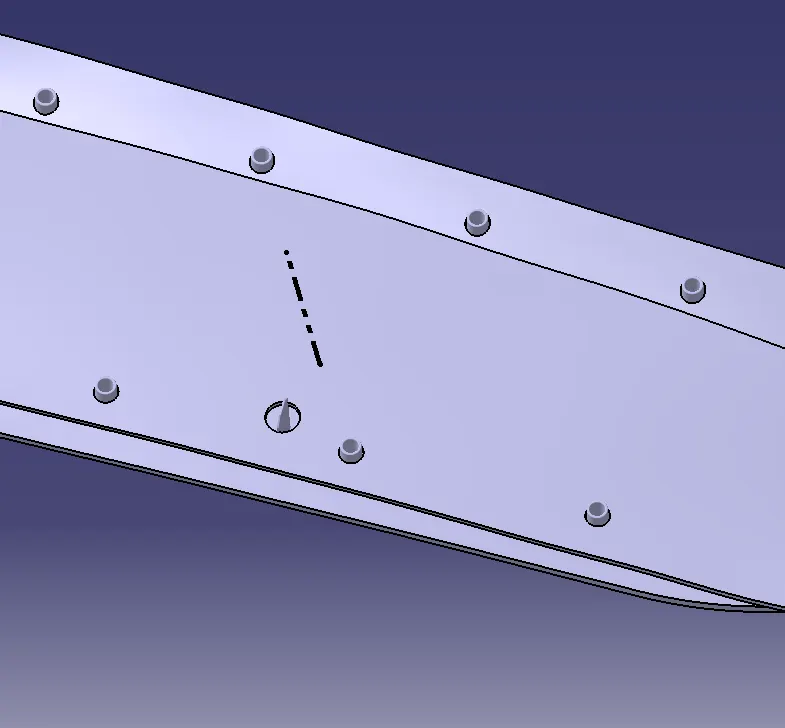
DRAFT ANALYSIS FEATURE OF THE COMPONENT
The Draft Analysis command enables you to detect if the part you drafted will be easily removed. This type of analysis is performed based on color ranges identifying zones on the analyzed element where the deviation from the draft direction at any point, corresponds to specified values.
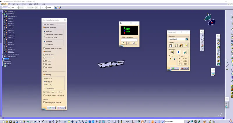
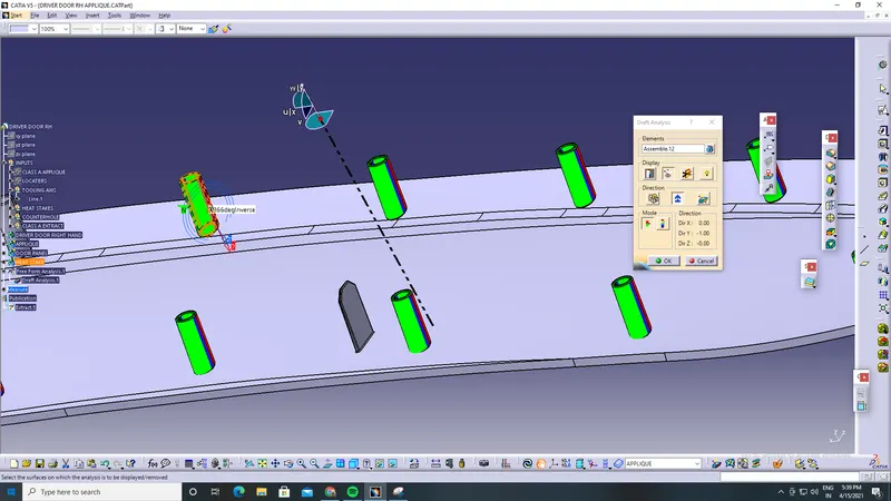
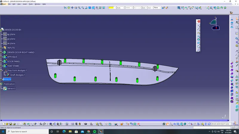
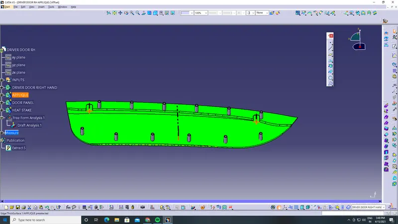
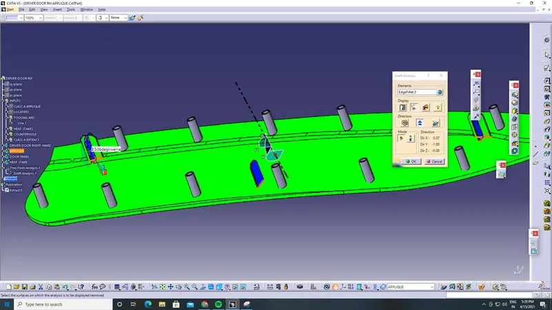
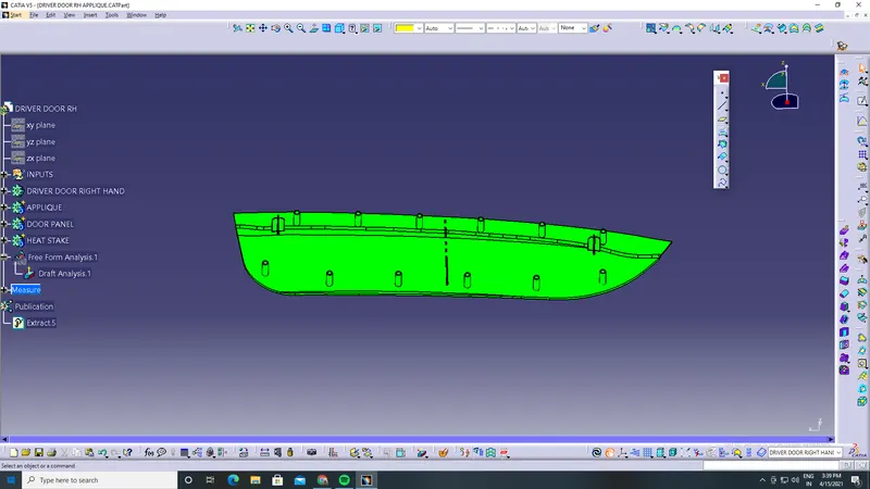
OUTPUT : Thus, the final B side and engineering features are done and my design of component is ready to manufacture and tested for component extracting from injection moulding with perfect tooling direction.