Week 8 - Challenge 2 - Base Bracket Design
DESIGN AND DRAFT ANALYSIS OF BASE BRACKET USING CATIA V5
SURFACES USED :
- CLASS A SURFACE
- CLASS B SURFACE
- CLASS C SURFACE
Using Class-A surface designing of base bracket was the main operation in this overview I,detailed explained how to design base bracket with reference of Class-A and creating Class-B & Class- C surface.
Complete 3DEXPERIENCE PLATFORM done with Shape generative design.
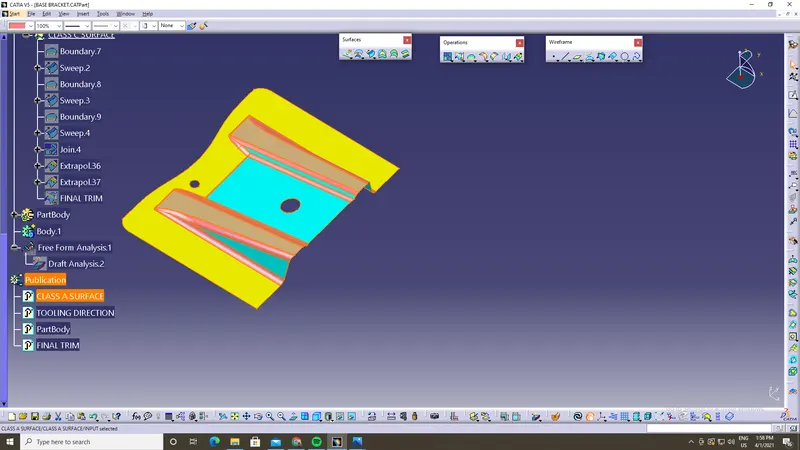
- REFERENCE OF CLASS-A SURFACE
- CREATING TOOLING DIRECTION :
Assuming drawing direction and creating plane & intersection of surface for drafting.
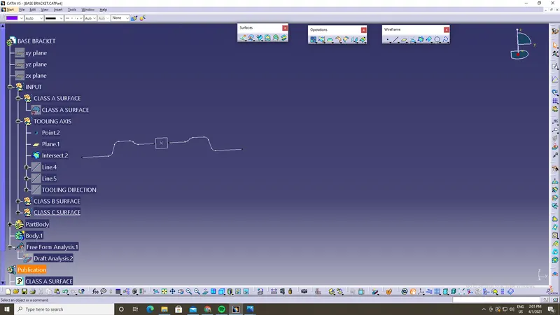
- Drawing lines to represent and bisect the lines and tooling directon.
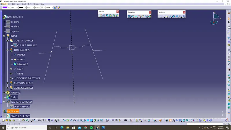
TOOLING DIRECTION REPRESENTED IN BLACK IMAGINARY LINE :
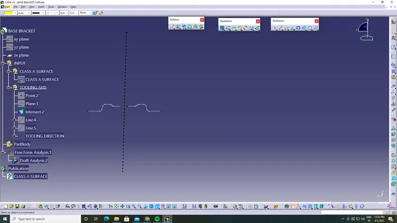
PROVING DRAFT ANALYSIS :
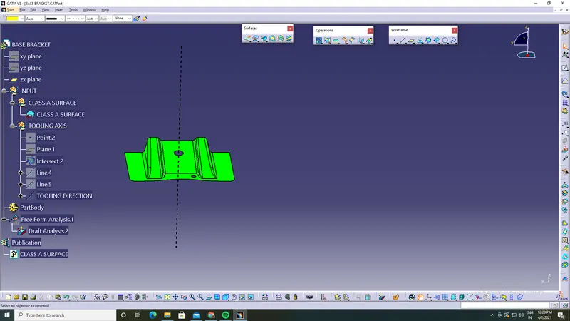
- GREEN COLOUR REPRESENTS TOOL CAN CLEAR TOOLING DIRECTIONS :
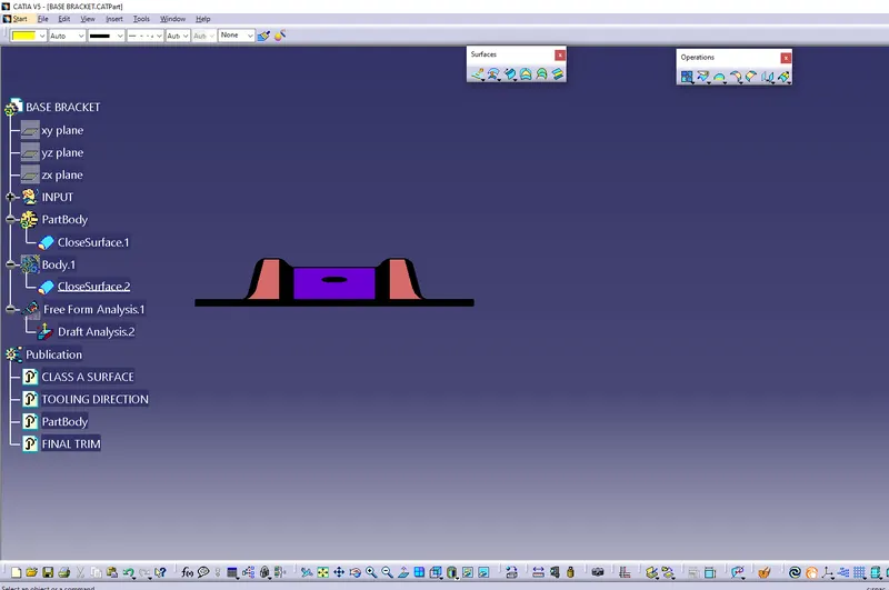
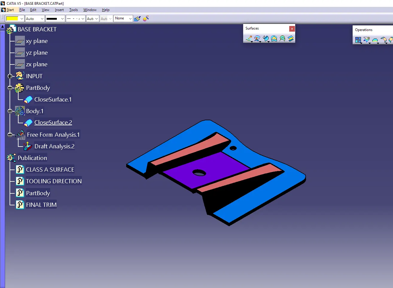
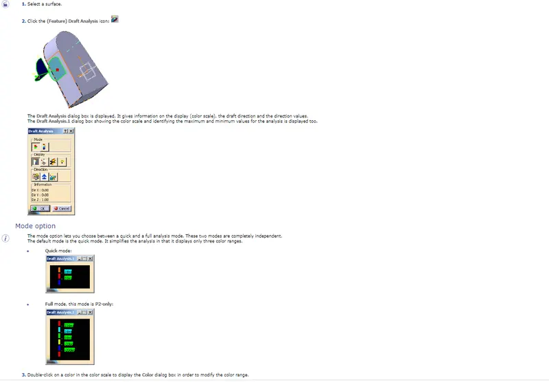
The Draft Analysis command enables you to detect if the part you drafted will be easily removed. This type of analysis is performed based on color ranges identifying zones on the analyzed element where the deviation from the draft direction at any point, corresponds to specified values.
NOW,COMING TO DESIGN PART TAKING THR REFERENCES OF CLASS- A SURFACE DESIGN THE BASE BRACKET :
Here are my images designed in catia,
Classification NAMED as step by step
- CLASS A SURFACE
- TOOLING AXIS
- CLASS B SURFACE
- RIB 1
- RIB 2
- BASE SURFACE
- FINAL TRIM
Creating Class-B surface
Operations used :
- extract
- untrim
- extrapolate
- offset
- edge fillet
- trim
- boundary
- join
Design of Rib 1 :
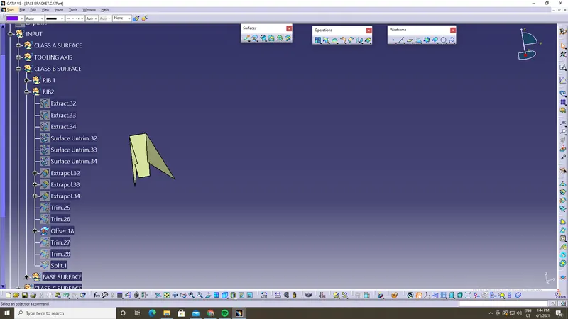
Design of Rib 2 :
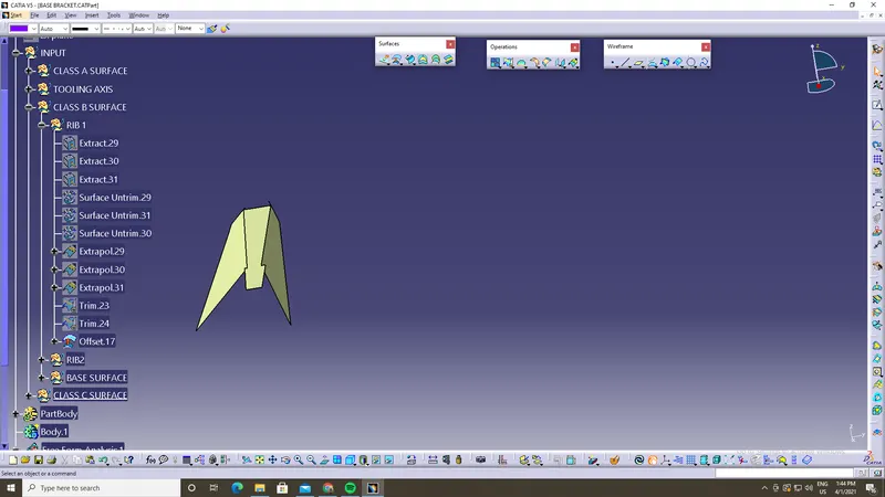
Base coupe
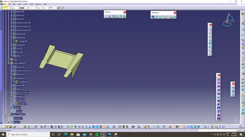
Designing Base part
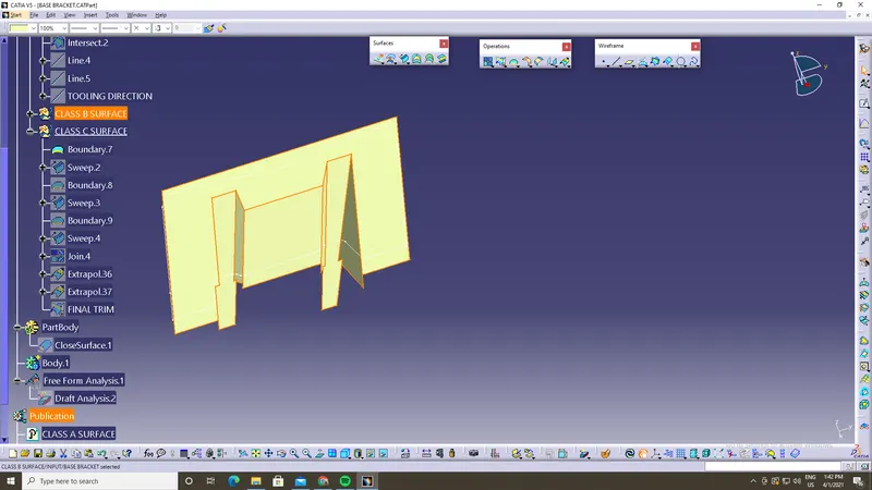
Final base surface -B Different view
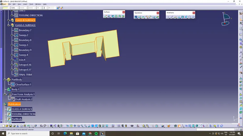
Creating Class C surface :
In class C surafce commands used :
- boundary
- sweep
- extrapolate
- join
- trim
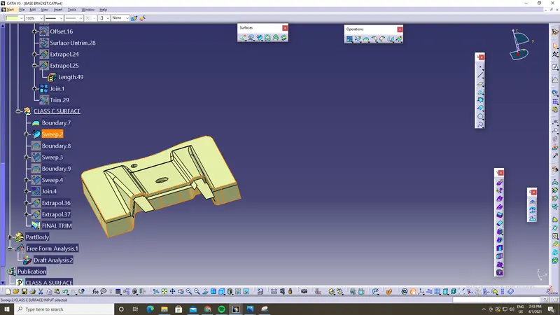
Final trim of class C surafce :
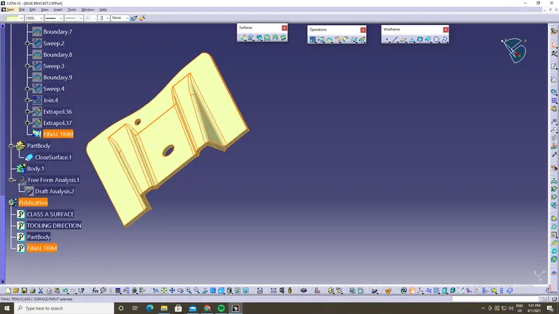
FINALLY
Checking for closed surface is final output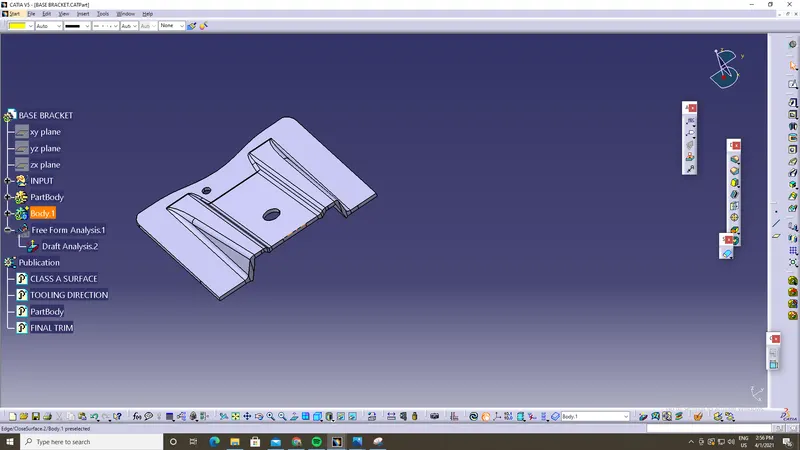
My fianl output diagram of base barcket.
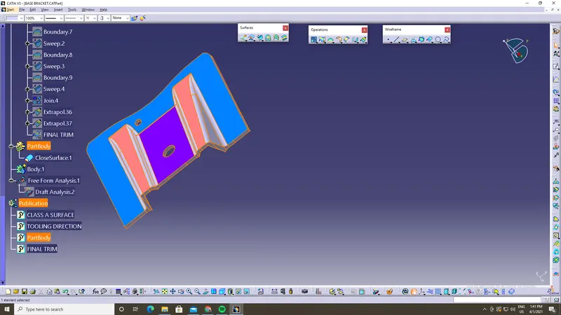
isometric view
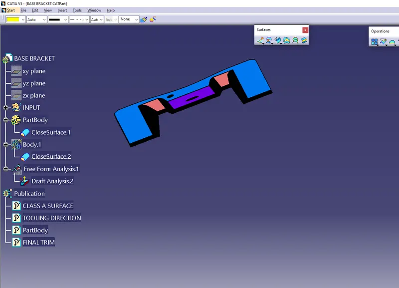
Front view :