Project 1 - Door Applique Design with Engineering Features.
Aim: Door Applique Design with Engineering Features.
Objective :
Create the Door Applique Plastic component through the given Class-A surface. To begin with, the tooling axis for the given Class-A Surface should be created meeting the requirements of the draft angle and at the end perform the Draft analysis on the model.
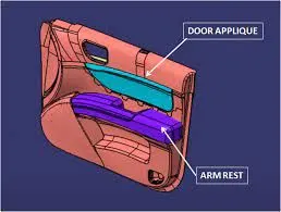
Create the Heat Stakes and the locators considering the design rules mentioned in the video for the door applique.
Detailed report :
Method followed :
- Created a tooling axis to perform draft analysis.
- Created a solid plastic component from given Class A.
- Created Heat Stakes and the locators considering the design rules.
- Performing a Draft Analysis on Class A and the Final component.
Procedure :
1. Created a tooling axis to perform the draft analysis :
- The model is opened and the class A surface is checked in all directions and the best direction is chosen that captures all the parts and features of the geometry.
Here the Y direction gives the proper view for the tooling axis.
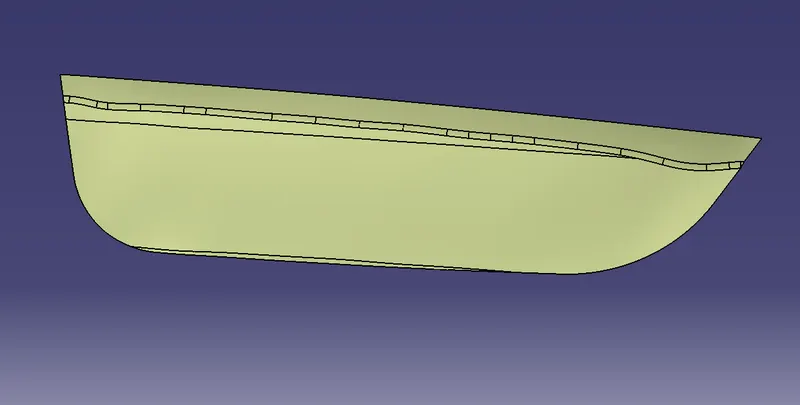
- Now, we know that the Y direction is from where the tooling axis is going to lie but we don’t know the direction for the axis.
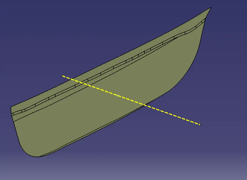
- So, the base is extracted and the point is created on the surface at the zero coordinate (center of the surface).
- Then at this point, a line or axis is created in the Y direction.
Draft analysis :
Draft analysis is required to check if a part has the required draft or not. The draft is required so that a part can be ejected from its mold. The Draft Analysis command enables you to detect if the part you drafted will be easily removed.
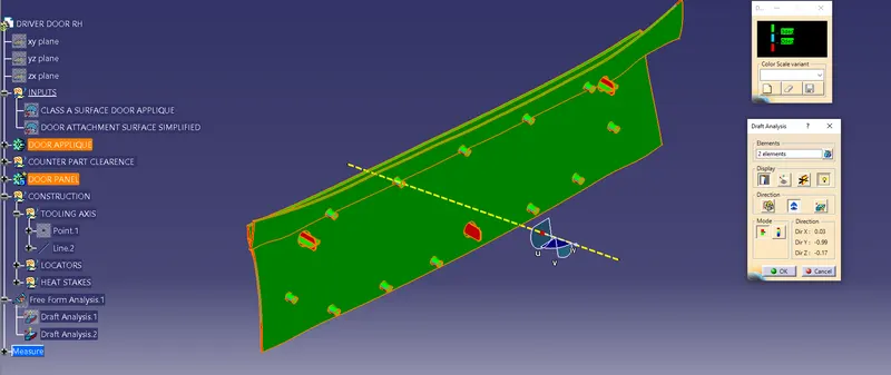
- To perform Draft Analysis, Go to the insert Menu > Click Analysis > Click Feature Draft Analysis option > New Dialog boxes open.
- Select the Elements as the Class A Model and the Direction as the Tooling Axis using the Compass option to define a new direction of the draft.
- Click OK to check if all the surface comes within the limits of 0 to 3 degrees.
- If the draft is more than 3 Degree then the surface will be shown as green.
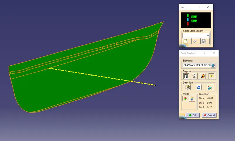
2. Created a solid plastic component from given Class A :
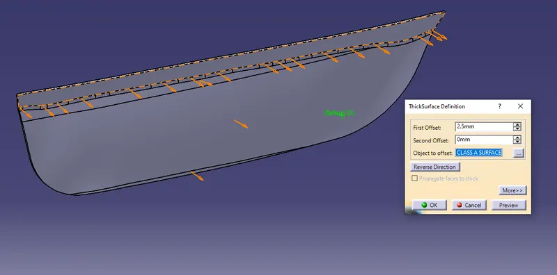
As we know, we have a Class A surface thickness of 2.5mm. So, we just created a solid plastic component by thickening Class A surface up to 2.5mm in a Part workbench through the Thick surface option.
Solid plastic component of Door Applique is given below,
3. Created Heat Stakes and the locators considering the design rules :
- Four-way locators
- Two-way locator
Four-way locators :
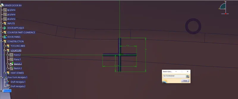
First of all, we need to create a positioned sketch, the ribs should be created intersecting and iso-constraint.
- Pad the created sketch thickness of 1.3mm in neutral fiber.
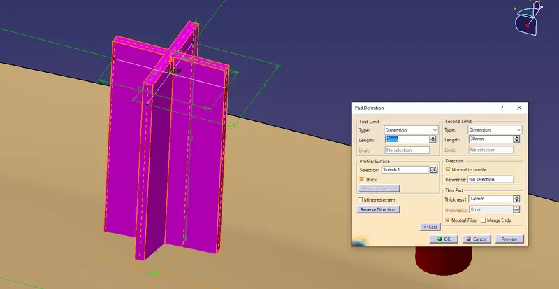
- Give a draft of 0.5 degrees of pulling direction of the tooling axis.
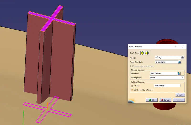
- Edge fillets of 0.3R on faces and 3R for edges after chamfering.
- Chamfer at 3mm*45 degrees.
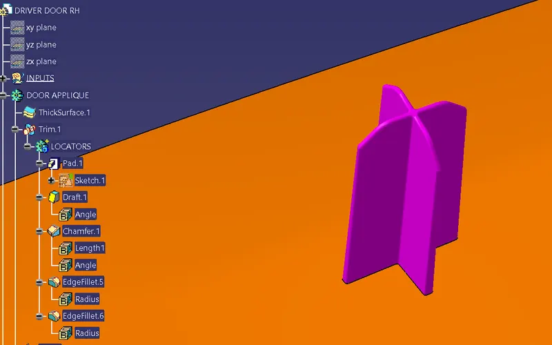
We get the 4-way locator now we need to make the same in other coordinates.
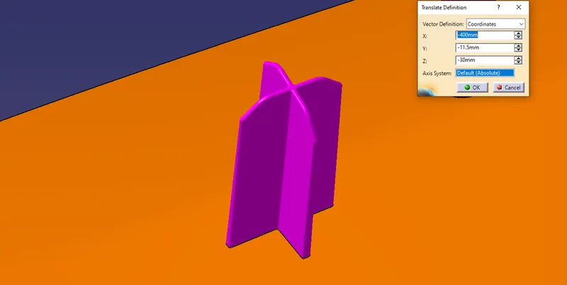
So, copied it and paste special it.
Transfer it on required coordinates as X = -400mm, Y=10mm, Z= -30mm.
Two-way locator :
For this, we created a sketch of a single rib and constraint it.
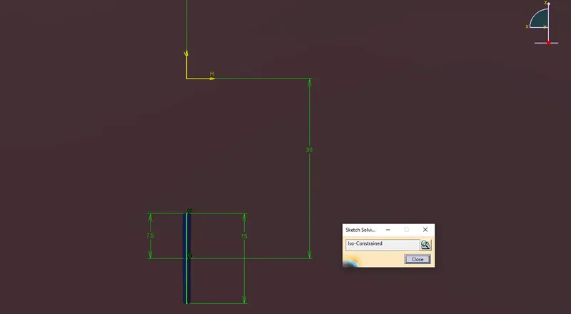
- Pad it of a thickness of 1.3mm.
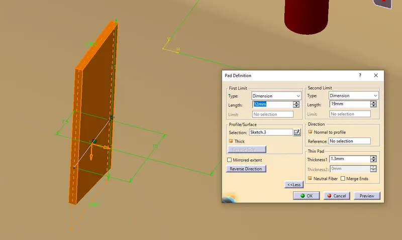
- Draft it at 0.5 degrees.
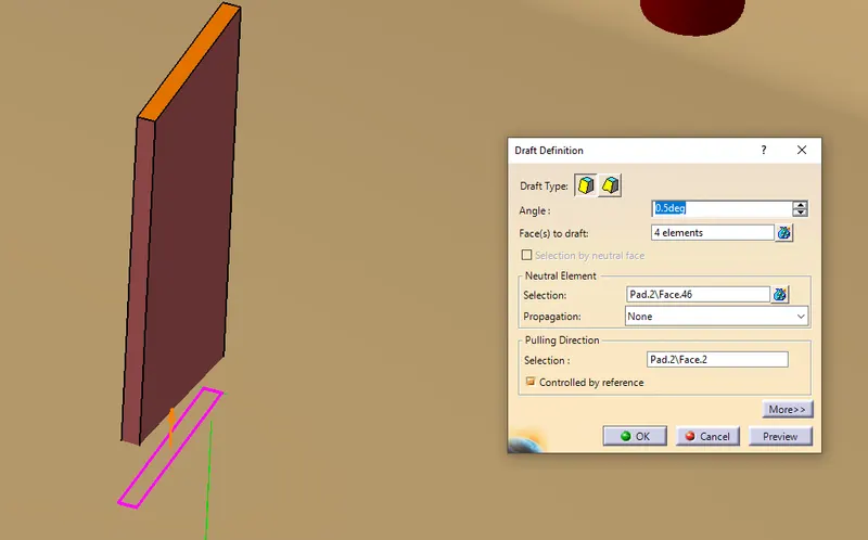
- Give fillets of 0.3R on faces and 3R for edges.
- Chamfer it of 3mm*45 degrees.
Make sure that the padding is extended through the solid body.
After that union trim all the locators with Door Applique.
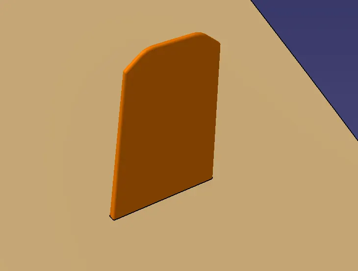
Heat stakes :
Since there are several heat stakes to create each time will consume time. Instead, we will use the translation option to locate the heat stakes. to assemble the two parts.
- So simply extract the upper and lower faces separately of Class A and offset it by 2.5mm then parallel curve it by a minimum of 15mm.
- After that make a point on the boundary by point and plane repetition command.
- For upper boundary instances of 5 and lower, it should be 8 instances at the constant of 15mm.
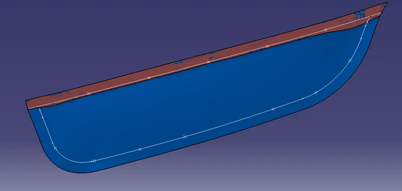
Make sure that the heat stakes are not interfacing on ribs and locators and if it is then remove that point.
- To create the Heat stakes, open the Sketcher Workbench and Draw 2 circles with the diameter of 7mm and 5mm respectively.
- Exit the Sketcher Workbench and Pad the Heat Stakes.
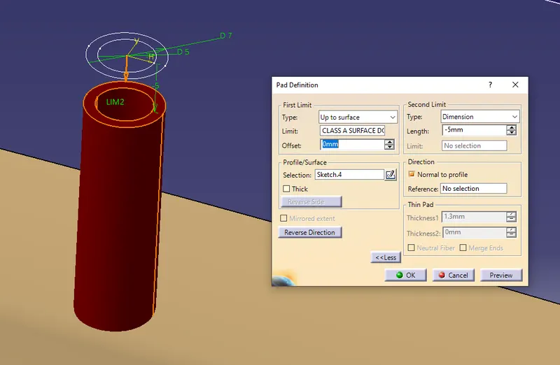
For making a heat stake on every point just copy & paste it as a given number of points then transfer it point to point.
- Assemble every heat stake to a new part body and name it as HEAT STAKE ASSEMBLY.
- Then union trims it with Door Applique.
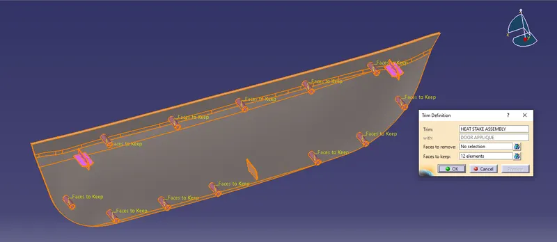
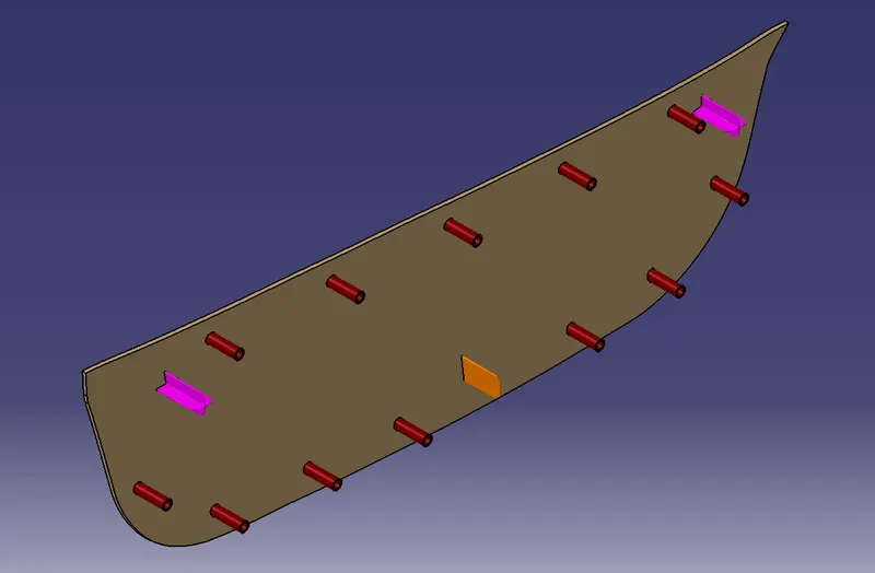
Making the Holes on the Door Attachment Component :
To show the assembly of Door Applique and Door panel we need to create counterpart clearance to the heat stakes and locators, follow the steps given below
- Make a circle in the sketch of clearance for heat stakes 0.1 clearance on each side and 0.05 clearance for locators i.e. R8 for heat stakes and R14.9 for locators.
- Pad it and give a draft angle of 0.5 degrees for locators.
- Transfer it on each heat stake and locator respectively.
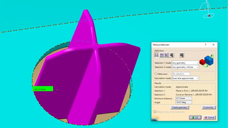
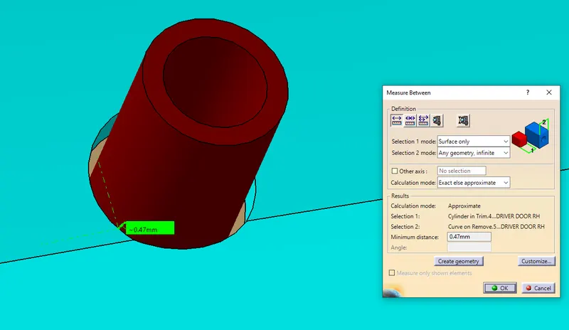
Then Remove it from Door Panel using Boolean Operation.
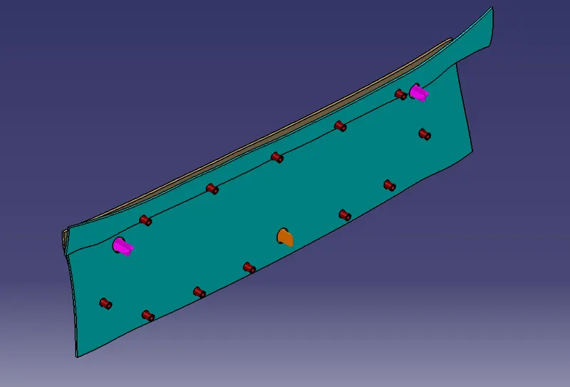
- Performing a Draft Analysis on Class A and the Final component :
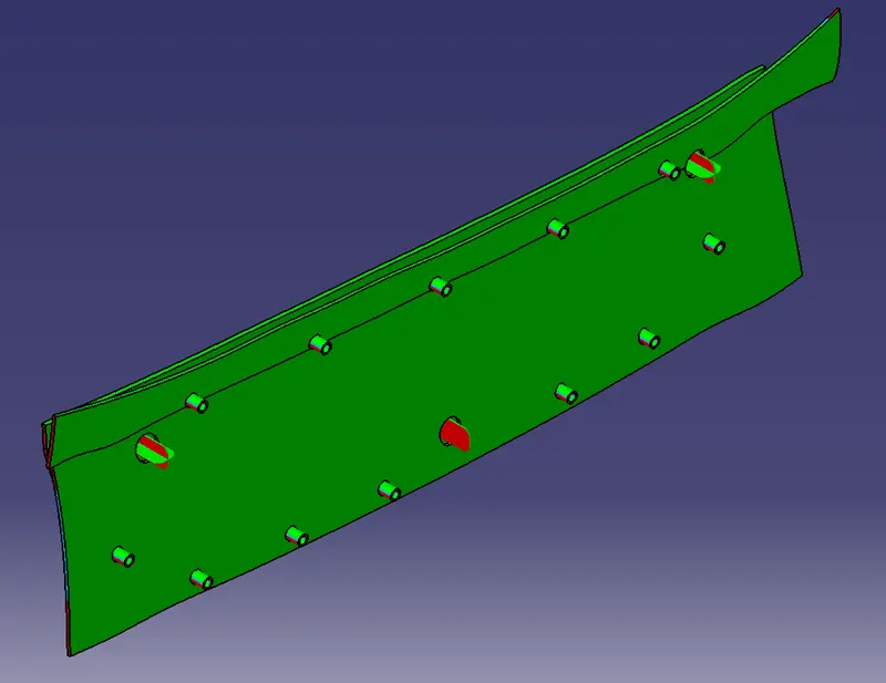
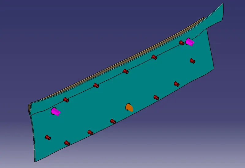
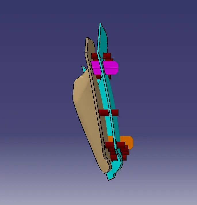
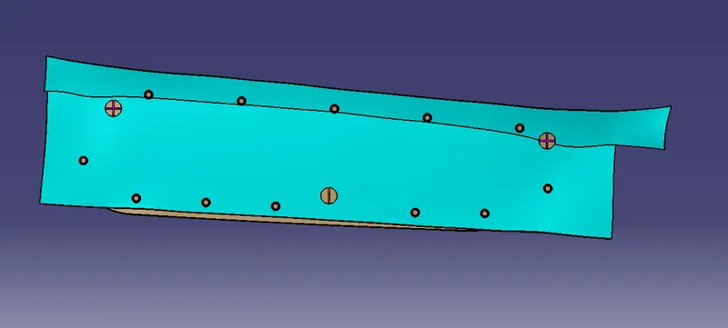
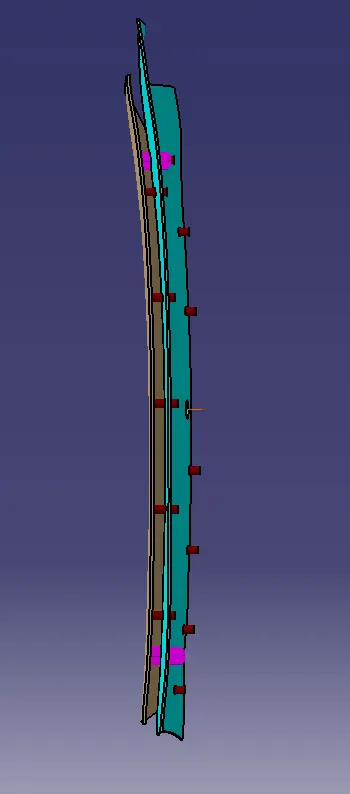
- Screenshots of the completed design in various orientations (Isometric, Front, Side, and Top View)
Isometric view :
Front view :
Side view :
Top view :
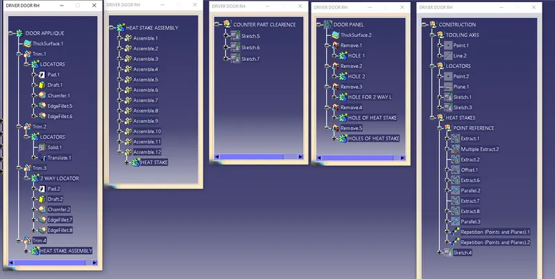
Geometrical Tree structure :