Week 9 - Project 1 - Door Applique Design with Engineering Features
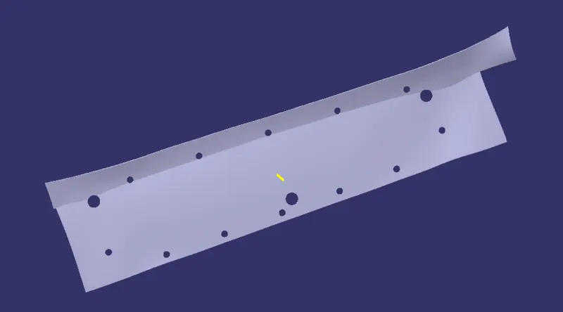
AIM:- To create a Door Applique from the given class A surface with engineering features such as Heat Stakes and Locators and also perform Draft Analysis on the final part body.
Create Tooling Axis:-
Tooling Axis
Tooling Direction is basically the direction that the core pulls apart from the cavity. And some components have ribs, pockets, walls.... are going to be drafted based on the Tooling Direction. So make sure the tooling direction which is cover all phases of the components and Core pull apart from the Cavity, nice and clean.
Here using Bisecting method to create a Tooling Axis. There are so many methods to create a Tooling Axis for differnt type of components.
Bisecting Line:-
- First visually check given class A surface for to find out tooling axis which is cover all faces. Herer in this case viewing from Z direction we can clear the face in tooling
- Most of the cases we create the point in holes and pockets of the part, because the holes and pockets is to create a problems when we do the daft ananlysis so we creat a point in mid of the hole. and create a axis system on it.a
- And using intersect command intersect the surface and draw the lines on the walls and create a disect line with help of b isecting line command.
But given Door Applique Class A surface all faces are cleared in y direction. So in order to create Tooling Axis in Y direction.
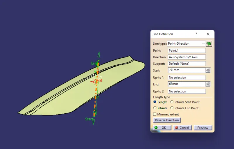
CLASS B SURFACE:-
Consider the thickness of the component is 2.5mm for create the Class B surface from given Class A surface.
First extract the all faces and offset it by 2.5mm.
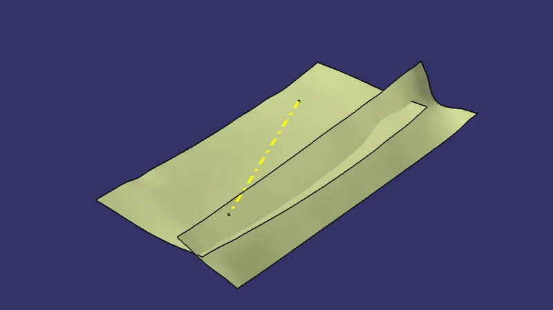
After that trim the surface and given fillet to it, the B suface is obtained.
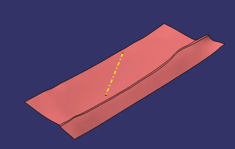
CLASS C SURFACE:-
For the Class C suface take a boundary of the Class A surface and sweep it anlong tooling axis with 3 degree of draft angle
c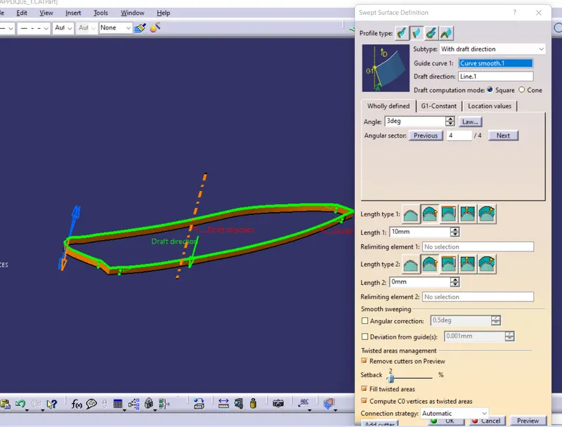
And then join Class A surface with Class C surface
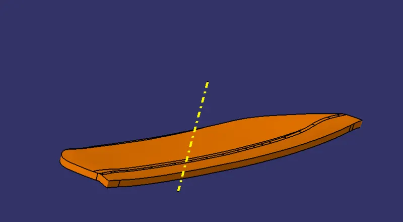
After that Trim with Class B surface
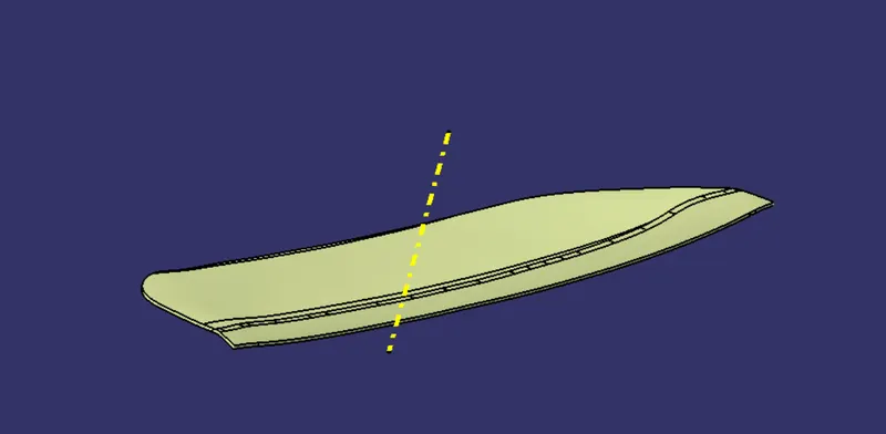
After close surface is obtained, to form a thick solid component.
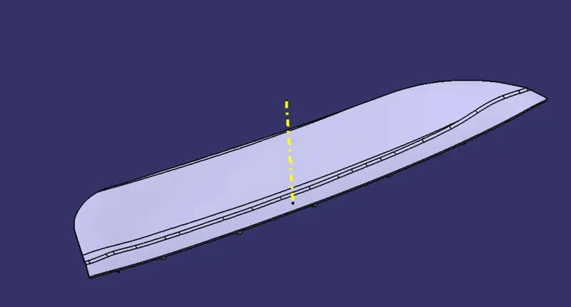
ENGINEERING FEATURES :-
4 WAY AND 2 WAY LOCATORS
Locators are a great way to make sure the parts we are putting together fit the way we want them to fit. The difference between a 4 way and a 2 way locator is that the 4way locator prevnets movement at 2 axis on the plane whereas a 2 way locator only prevents movement at 1 axis on the plane.
To create a 4 way locator, we need to create a sketch with two lines intersecting each other perpendicular forming a '+'. Once the sketch is created. pad it to form a locator.
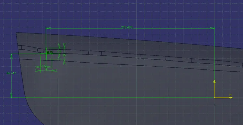
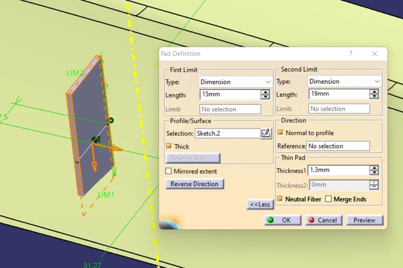
pad the sketch with a thickness of 1.2mm.
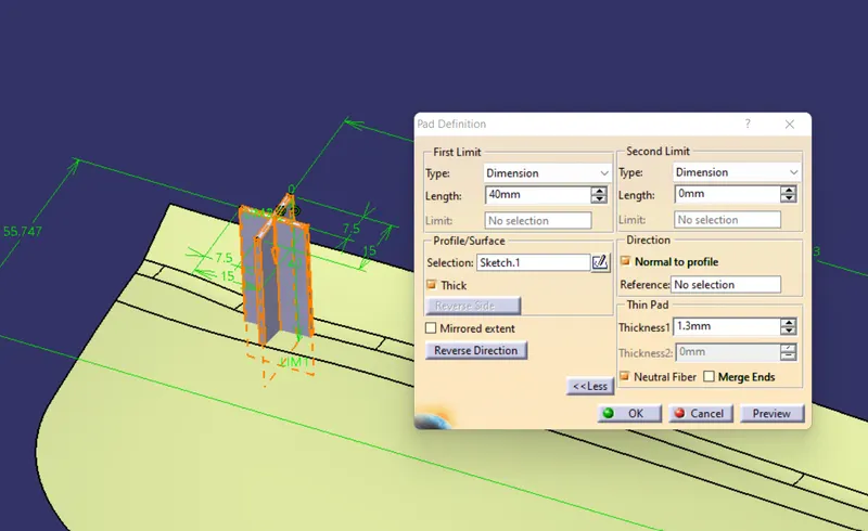
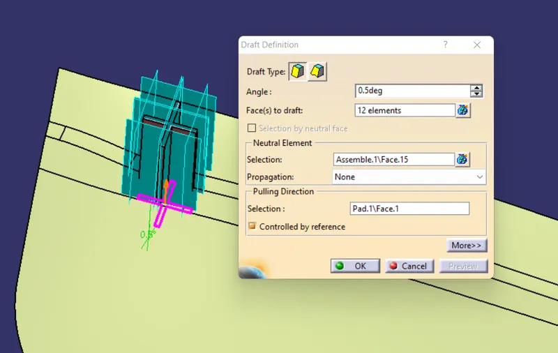
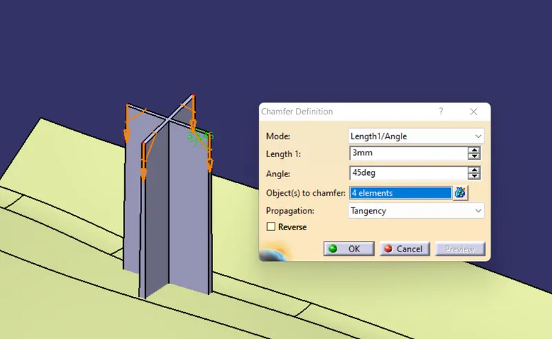
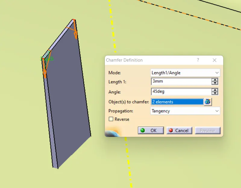
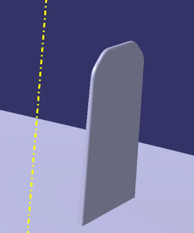
Now draft the faces with 0.5degree. Here neutral face is top face and also provide the chamfer of 3*45 to the edges of the locators
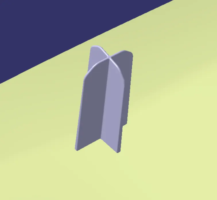
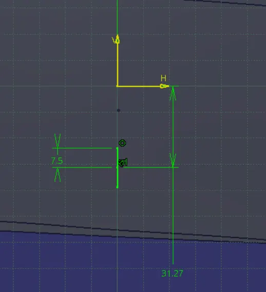
By creatng a new sketch with a single line, simillar operation can be performed to form a 2 way locators
HEAT STAKES:-
Heat Stakes are used to join two or more parts that are made of plastic with the help of heat staking process. Heat staking process involves deformation of the platic material using heat and force to fix it with the other parts.
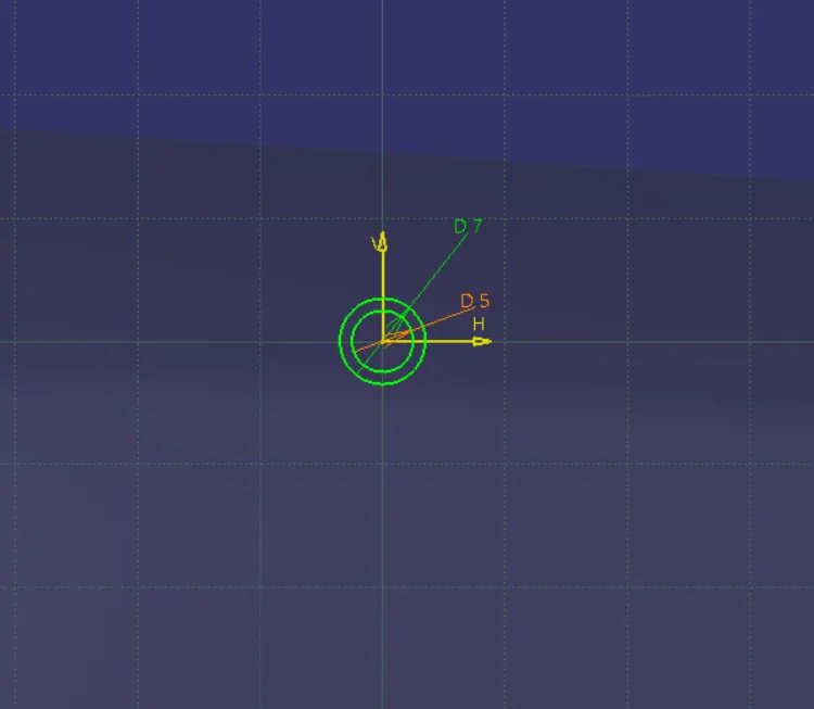
To create the heat stakes, we need to create a sketch with 2 circles of diameter 5mm and 7mm respectively. Now pad this sketch to form a solid and give it a draft of 0.5 degree.
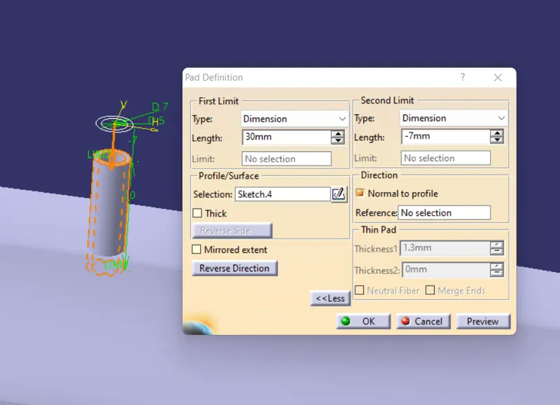
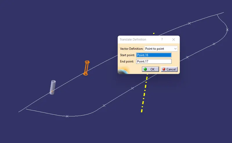
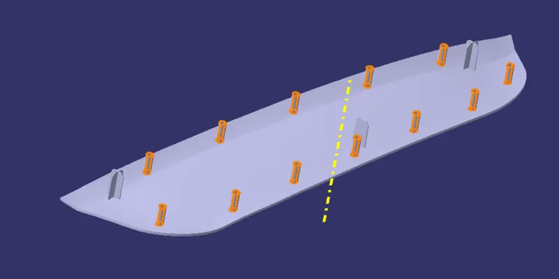
In order to fit the Door Applique to Door Attachment we need more number of heat stakes. This can be done easily by using the translate option.
To translate the heat stakes we need points which are 50mm apart from each other. In order to create these points we first need to extract the boundary of the Door Applique. Now using this boundary a parallel curve is created at a distance of 15mm
Creating Holes on the Door Attachment:-
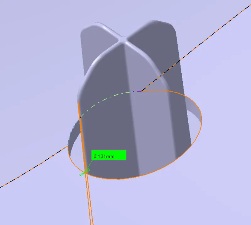
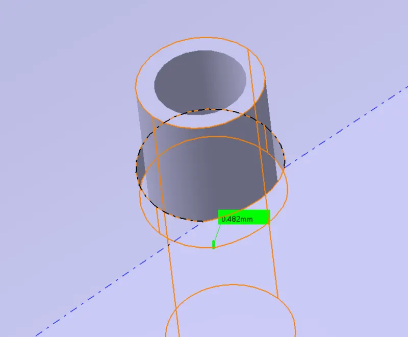
In order to fit the Door Applique on to the Door Attachment we need holes on the Door Attachment opposite to the locators and Heat stakes.
The holes on the attachment must be created considering a clearance of 0.1mm for the locators and 0.5mm for the heat stakes.
Draft Analysis:-
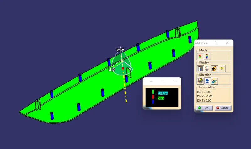
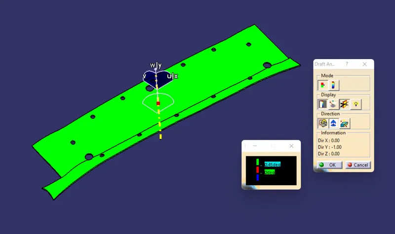
The Draft Analysis command enables you to detect if the part you drafted will be easily removed. This type of analysis is performed based on color ranges identifying zones on the analyzed element where the deviation from the draft direction at any point, corresponds to specified values.
- To perform the darft analysis the view parameters are first set to material mode.
- then go to insert -analysis-feature draft analysis, the following window will be appeared.
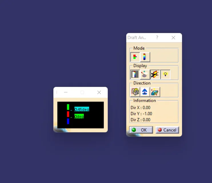
- First select the axis system and drag the axis system to the tooling axis and lock the orientation. This axis system defines the draft direction according to the tooling axis
- Switch on the colour scale and set the draft value 3 degree using colour scale and it will be displayed in green colour any draft angle below 3degree will be shown in red colour.
- Now select the runing point tool to measure the draft angle at the various locations.
DRAFT ANALYSIS ON DOOR APPLIQUE
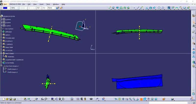
DRAFT ANALYSIS ON DOOR PANEL
RESULT:-
Door Applique plastic component with engineering features using a Class A surface have beeb successfully created and draft analysis have also been performed for the same.