Week 9 - Project 1 - Door Applique Design with Engineering Features
DOOR APPLIQUE DESIGN WITH ENGINEERING FEATURES
AIM:
Create a door applique with the given Class A surface and create features on the applique like locators (Four way and two way) and heat stacks, so that it will firmly grips the door and arrest all degrees of freedom.
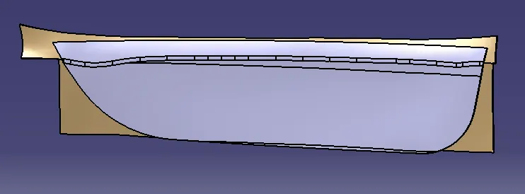
Given Class A surface
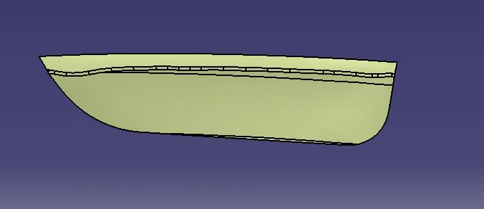
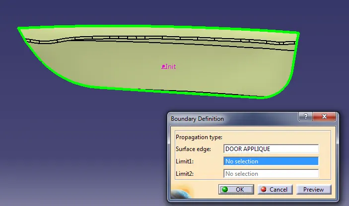
First we have to check if there is any discontinuity in the surface.
TOOLING AXIS CREATION:
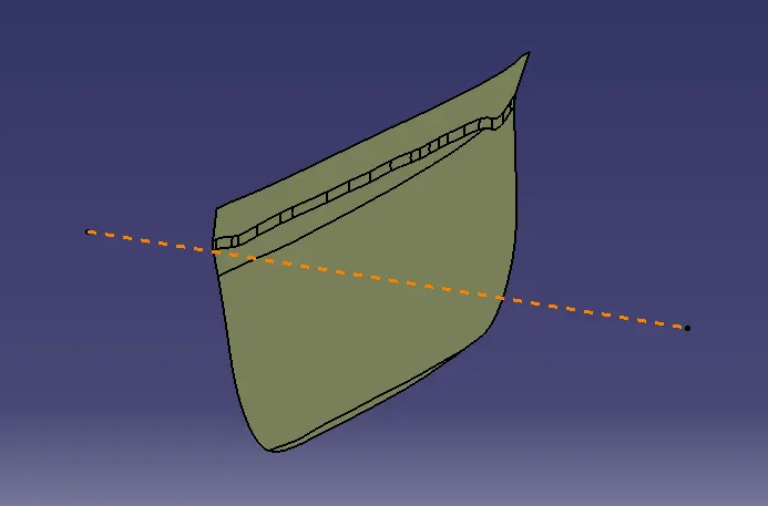
Then we have to create the tooling axis. Tooling axis is the direction along which the core and the cavity opens and the product is manufactured. Analyze the component and decide which will be the best tooling axis for the component , so that it can be easily manufacturable.
Tooling axis for this component is taken along the XZ plane. So we draw a line through the center of the door applique along the Y axis. It will be the tooling axis of this component.
DRAFT ANALYSIS:
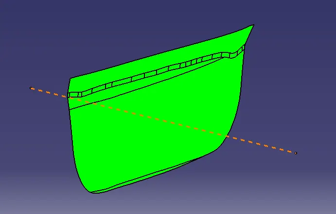
To make it easy to remove parts from mold, we put draft angle on the surface.
Draft analysis result of the component.
CLASS B AND C SURFACE CREATION:
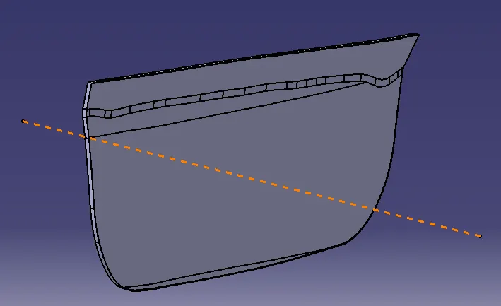
Now we have to create Class B and C surfaces. The surface A is offset for 2.5 mm, which is the thickness of the component. It acts as Class B surface. After that the boundary of the class A surface is swept along the direction of tooling axis to get the Class C surface.
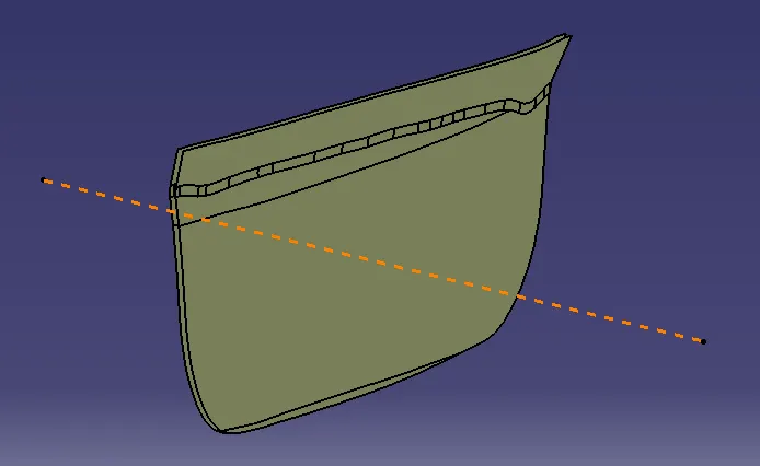
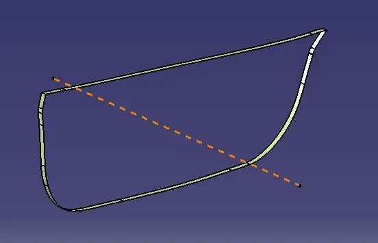
After that, trim the Class A+C surface with the class B surface to get the required surface. Then using the close surface command in the part design to get the part in solid.
ENGINEERING FEATURE DESIGN:
Now we have to think, how the plastic part is fixed with the other plastic part. The door applique is fixed on the door surface with the help of locators and heat stacks.
Every component in space has 12 degrees of freedom.So the locators and heat stakes arrest all these degrees of freedom.
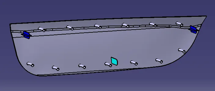
There are two types of locators- 4 way locators and 2 way locators. All locators will follow the ribe design rules and will be given a minimum draft 0.5 degree, fillet 0.2mm and entry chamber 3mm. The entry chamfer is given for easy assembly with mate parts.
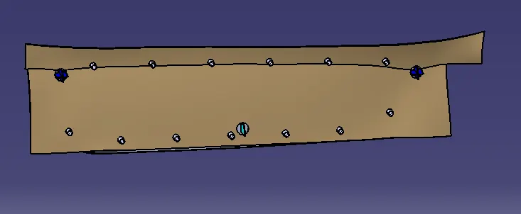
In below image
There are two 4 way locators in Blue colour, one 2 way lcatore in Cyan colour and 13 nos of Heat stacks in grey colour.
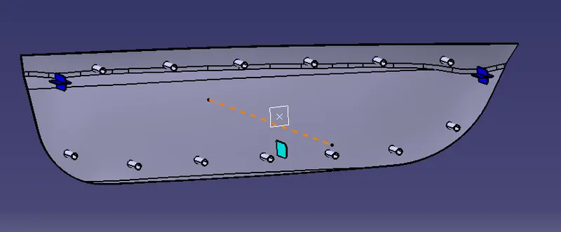
Provided locators restrict all the degrees of freedom except the translation along the direction of the tooling axis. For restricting that degree of freedom we will be using the heat stakes.
Heat stakes are heated and get melted by using a heat staking machine then reform, and prevent translation along the tooling direction.
The locators and heat stakes need to enter the mating component, the mating component is given a circular cut out in which the all engineering feature will enter in it and fix with door applique. The cut will maintain 0.1mm of clearance per side with all locators.
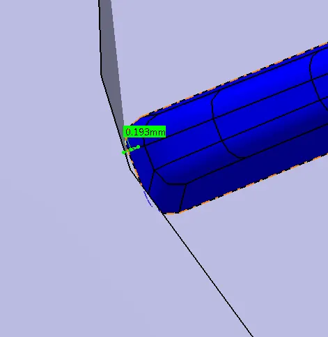
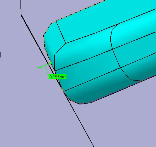
And for the heat stacks maintain a clearance of 0.5 mm per side.
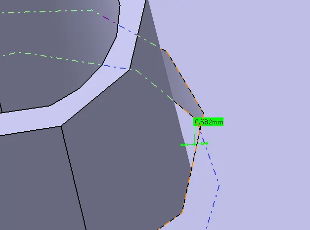
Draft analysis of final output.
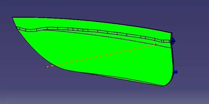
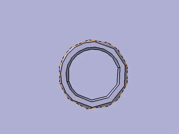
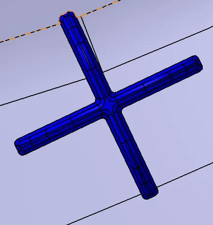
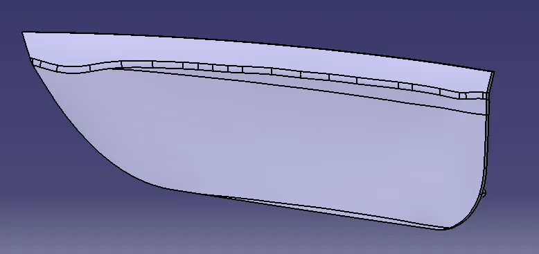
View of Final outputs.
View of assembly with counterpart.