Week 8 - Challenge 3 - Switch Bezel Design
AIM:
Perform draft analysis of given class A surface of switch bezel catia model and creation of Class B & Class C surface creation to get solid part out of it. Perform draft analysis of both class surface A and output solid component.With considering part thickness is 2.5mm.
OBJECTIVE:
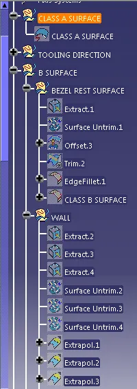
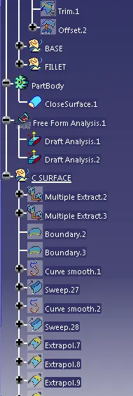
Ensure proper tree structure
Ensure proper names for every geometrical set according to sketches.
All sketches should be under the geometrical set.
Use the Close Surface feature to make a solid body from the surface.
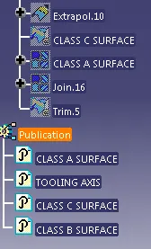
Publication of tooling axis and class A, B and C surface.
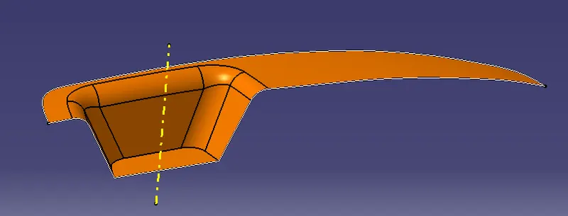
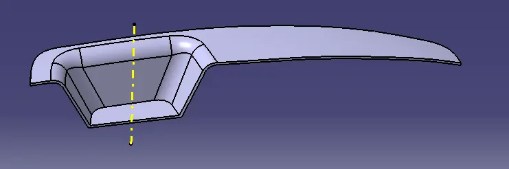
Provided Class A surface after importing in CATIA
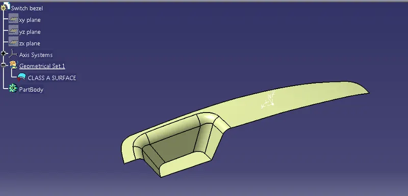
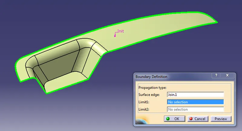
1st we have to check the connectivity of the surface.whether the surface provided has any discontinuity in it. It will be done by creating a boundary or by using the joining command.
Tooling axis creation:
Then analyze all surfaces for the possibility of tooling clearing all surfaces. Let’s start considering the Y direction. First create a point on the base surface and insert an axis system at that point. Then go to a positioned sketch to create a tooling axis along the Y direction.
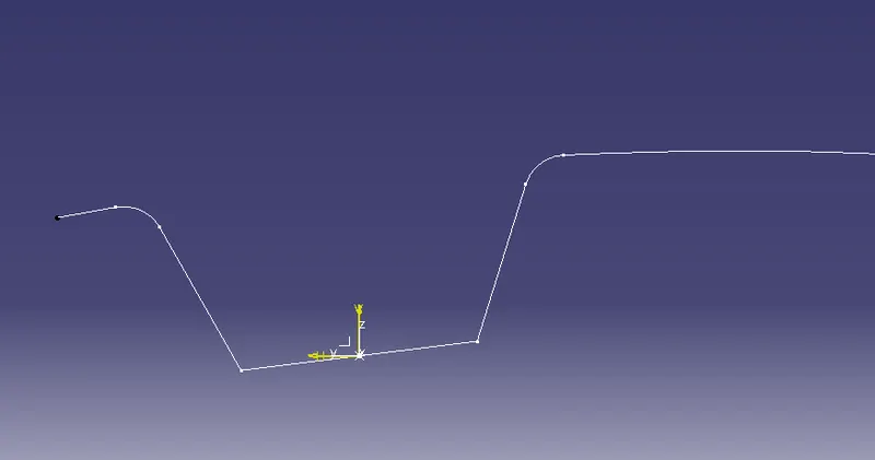
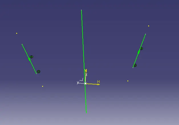
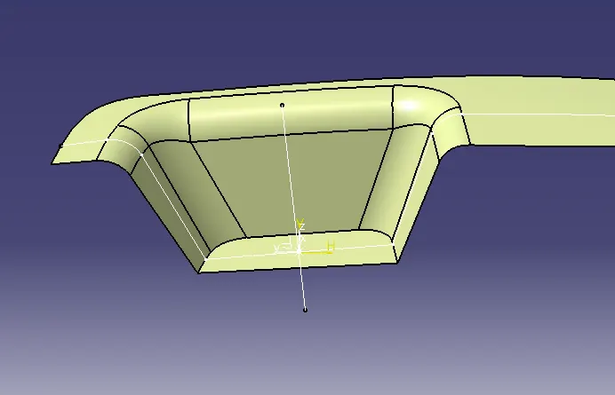
Next do the same process to get tooling directions along the X direction..
Take the intersection of the component along the XZ plane. In this case there is only one face which may create a problem. So we will sketch another line which makes an angle with the surface.
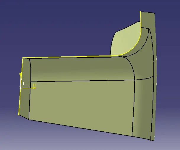
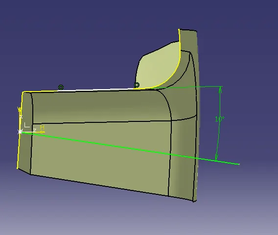
Now we got the two tooling axis along both X and Y direction.
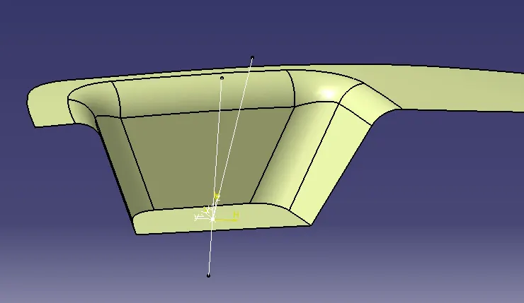
Then bisect those lines to get the final tooling axis.
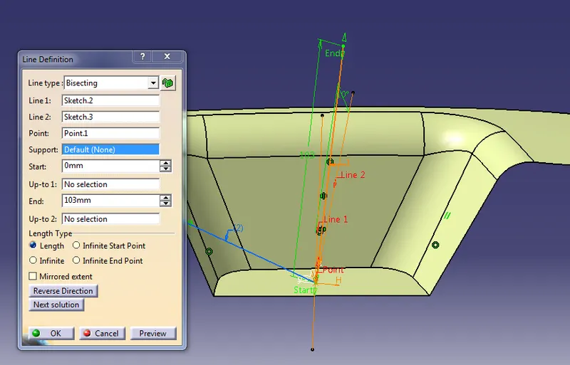
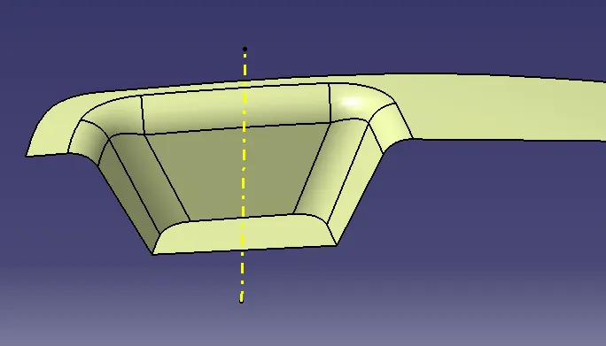
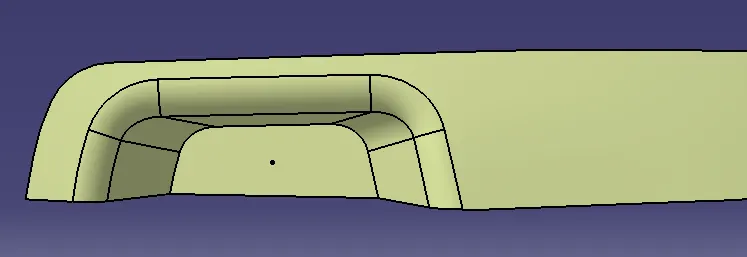
Draft Analysis:
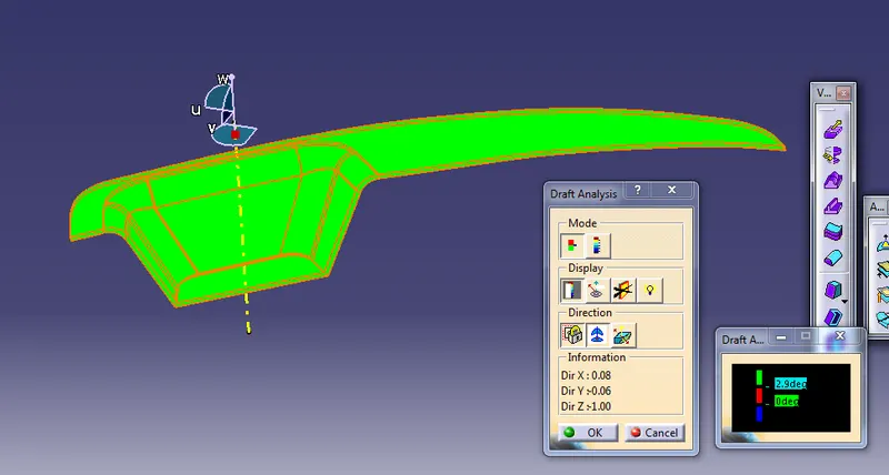
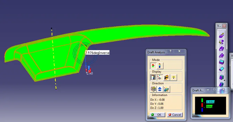
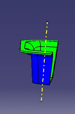
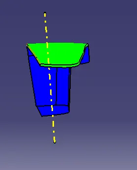
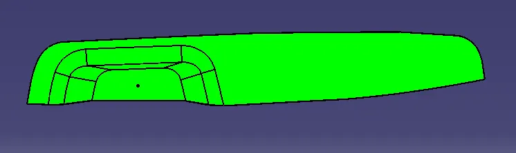
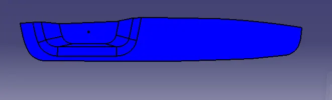
To perform draft analysis on the model: go to Menu bar > Analysis > Feature Draft analysis. We have to select customize the material mode under the shading option.
For draft analysis, the surface model and tooling axis are the inputs. For easy to remove parts from mold, the minimum draft angle is 3 degrees.
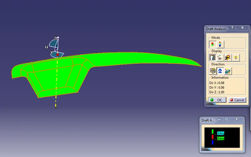
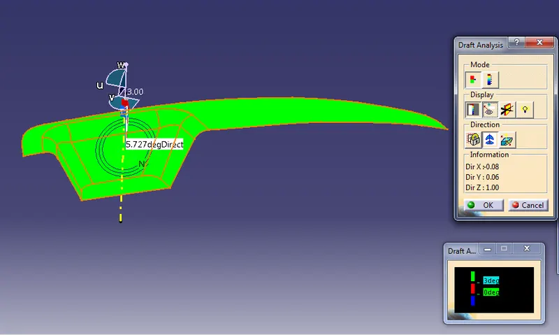
B Surface Creation:
At first we extract all surfaces excluding the filets. (Images are attache all surface in one bic, But i performed single single surface)
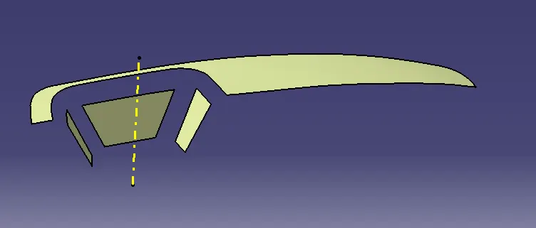
Then perform untrim, extrapolate,offset, trim and filets as sequence.
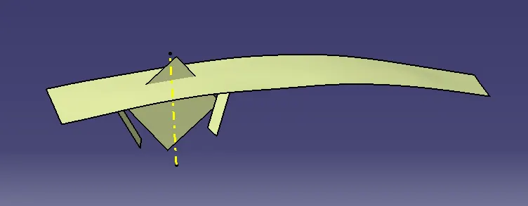
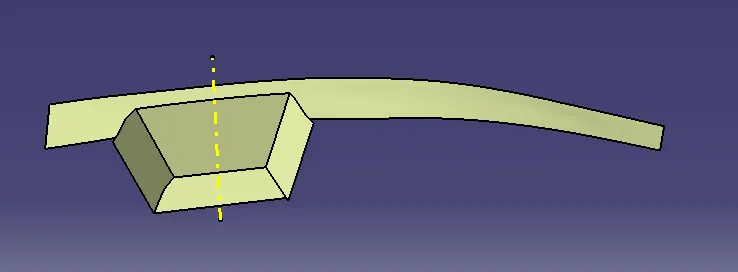
Final out-put class B Surface
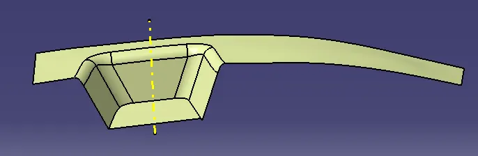
C Surface Creation:
At first we extract edges by boundry command of class A surface and use smooth curve.
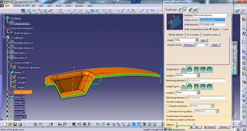
Then perform sweep operation with a draft angle 3 degree in both side edges of the class A surface.
Then perform extrapolate and trim to get final class C surface.
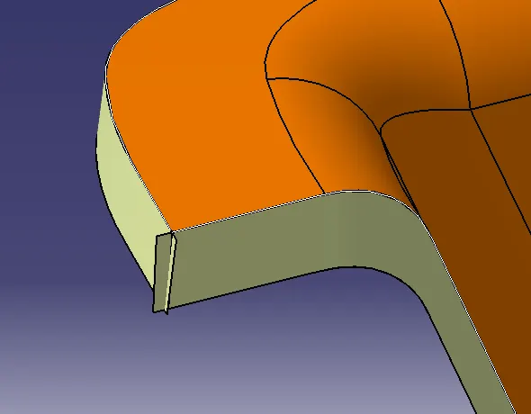
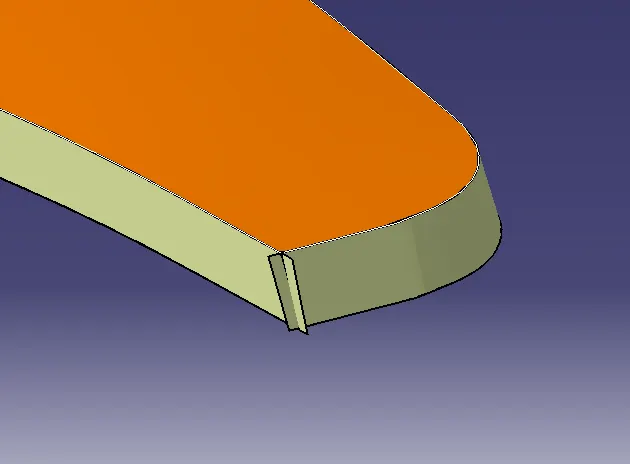
Final out-put class C surface
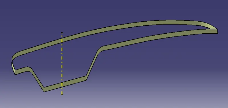
Final component in surface:
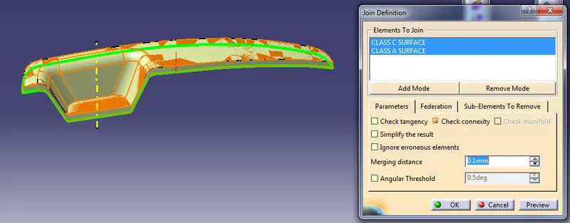
Now perform join commane taking input as Class C and A surface
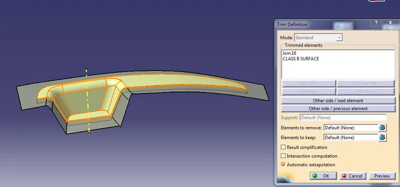
Then do trim with the class B surface.
Final component in Surface
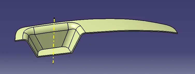
Final component in Solid
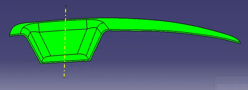
Draft analysys of Solid component:
Front View
Side View
Top View
Bottom View
Publication:
Publication of Class A surface, Tooling axis, B surface and C surface
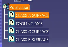
Tree Structure: