Week 8 - Challenge 1 - Draft Analysis on a Fan Cover
AIM:
To perform draft analysis with tooling axis creation on a given Fan Cover catia model which satisfies all the rules of draft angles.
OBJECTIVES:
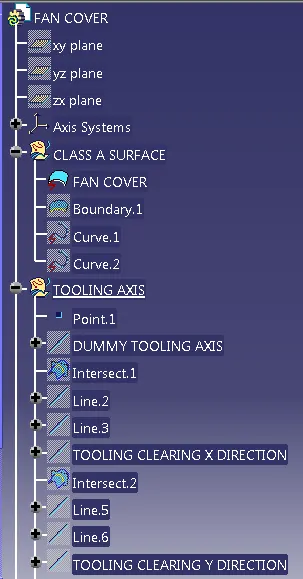
Ensure proper tree structure
Ensure proper names for every geometrical set according to sketches.
All sketches should be under the geometrical set.
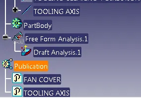
Publication of tooling axis and class A surface.
OPERATION INVOLVED:
DRAFT ANGLE: Amount of taper applied on molded or casted parts perpendicular to the parting line is called Draft and the angle between those lines is called Draft angle.It is applied on each side of the component and most of the feature.
PULLING DIRECTION: The direction in which the part is ejected/released from the mold is called pulling direction.
TOOLING AXIS: The axis in which the core moves to open and eject the component is called tooling axis.
NEUTRAL ELEMENT: It is the neutral curve on which the drafted angle will lie. Neutral and parting lines may be the same in some cases.
DRAFT ANALYSIS: It’s a command or tool to verify/detect if the part will be easily removable or not, from mold at the time of ejection.
1st we have to check the connectivity of the surface. It will be done by creating a boundary or by using the joining command. Ensure that there are no gaps between surfaces. Then disassemble the boundary.
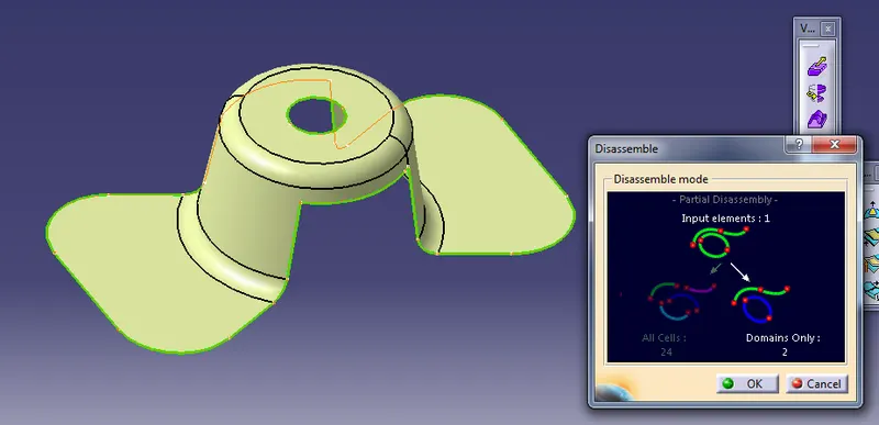
Analyze visually for the best possible tooling axis.Insert axis system.
A dummy tooling axis will be created directly using point and direction command
Checking clearance in all the axis directions will be done by creating an intersection along X and Y plane.
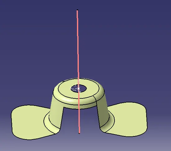
Creating tooling direction along X axis:
Creating intersection checking along the X axis, Checking all cross section lines are bisecting the tooling axis or not.In this case we took both side wall surfaces for check. It may create errors for tooling axis creation. So we create those two lines by using a bisecting line command on the ZX plane. The two lines and point are the input for the creating tooling axis along the X axis.
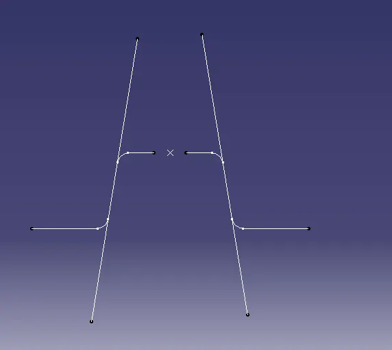
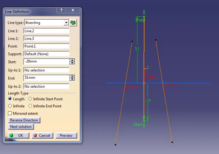
Creating tooling direction along Y axis:
Now do the same procedure in Y direction as well to get tooling direction. Here the intersection plane is the YZ plane.
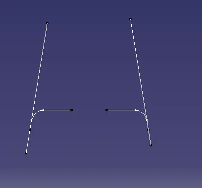
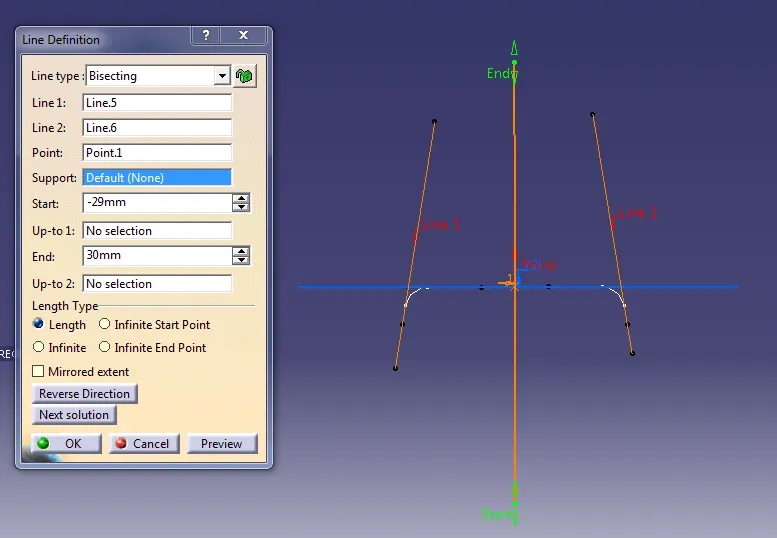
Now create the final toolong axis in the Z direction for class A using bisecting taking both X and Y direction clearing axis.
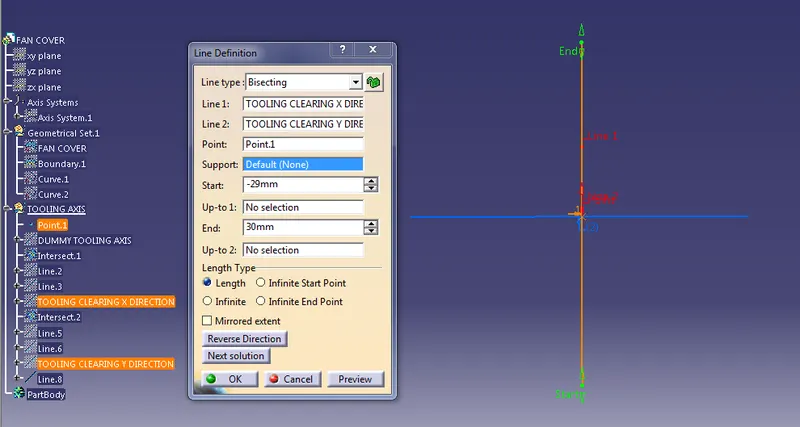
Publication:
For easy access, we use the publication command to keep inputs as separate publication under the tree.
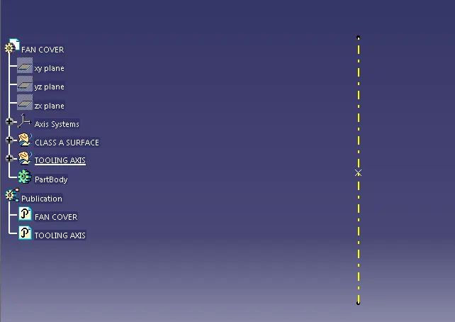
Draft analysis:
To perform draft analysis on the model: go to Menu bar > Analysis > Feature Draft analysis. We have to select customize the material mode under the shading option.
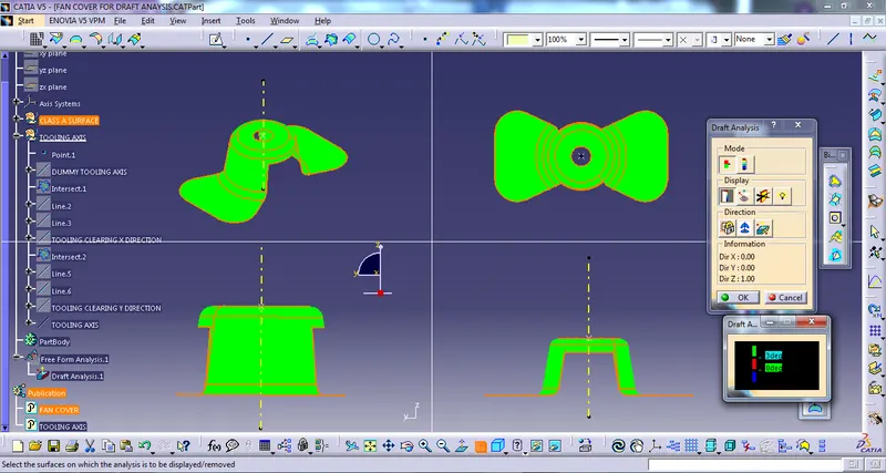
For draft analysis, the surface model and tooling axis are the inputs. For easy to remove parts from mold, the minimum draft angle is 3 degrees.
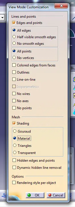
Compass will be used to determine the draft direction
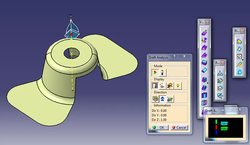
After placing the compass, select lock and then select part for start analysis.
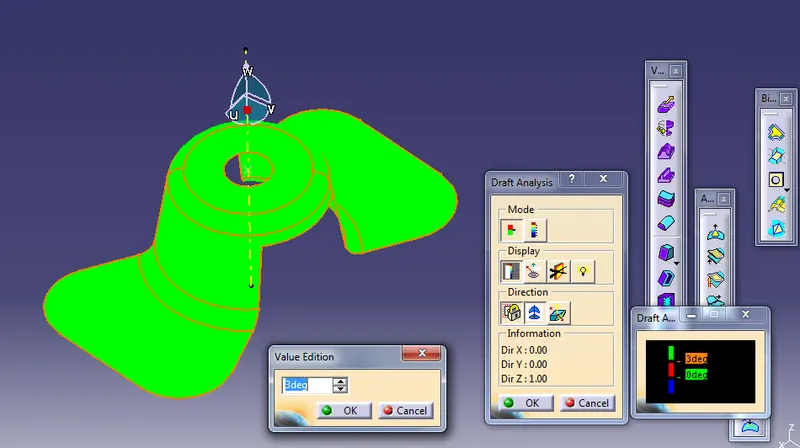
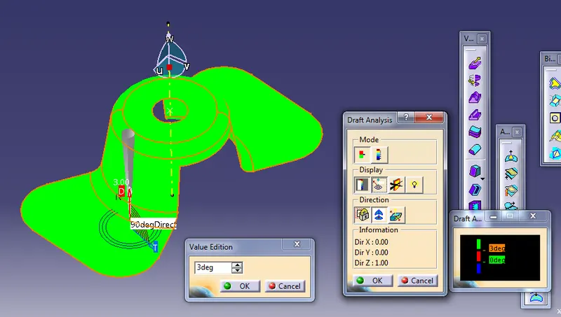
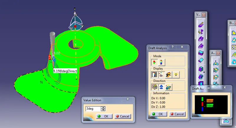
Minimum or more then 3 degree draft angle is provided in the surface model, So it shows Green in color. In the Draft Analysis box more than 3 degrees is Green, Zero degree is in Red and Negative is in Blue.
Result:
Here draft analysis shows the drafted walls of fan cover model are above 3 degree, which is permissable to manufacture in injection modeling.