Week 8 - Challenge 2 - Base Bracket Design
AIM:
To perform draft analysis with tooling axis creation on a given Base Bracket catia model and creation of Class B & Class C surface creation to get solid part out of it.
OBJECTIVE:
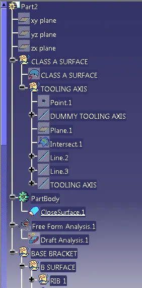
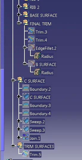
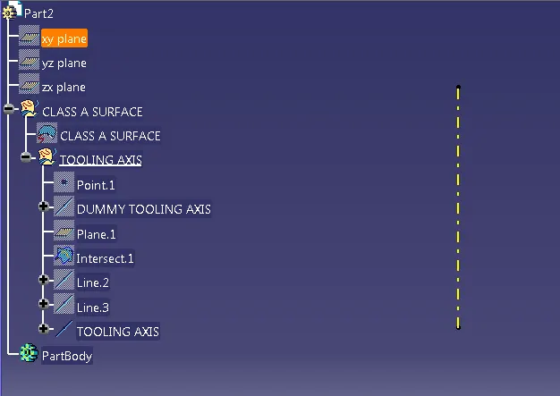
Ensure proper tree structure
Ensure proper names for every geometrical set according to sketches.
All sketches should be under the geometrical set.
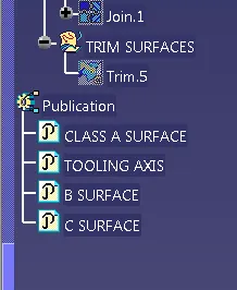
Publication of tooling axis and class A, B and C surface
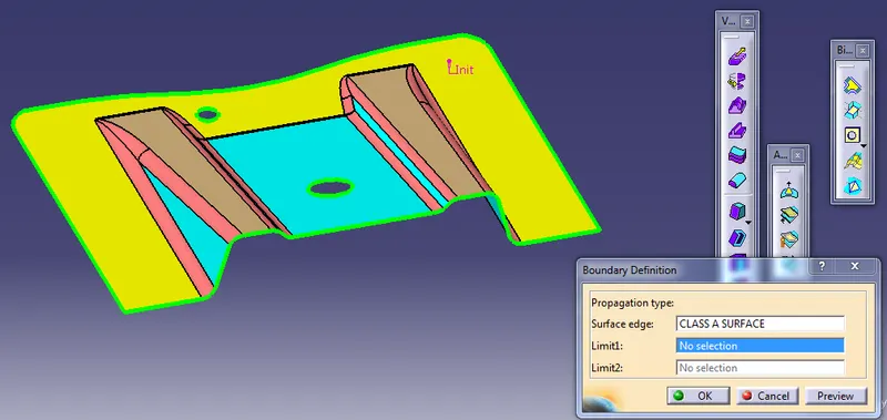
1st we have to check the connectivity of the surface. It will be done by creating a boundary or by using the joining command. Ensure that there are no gaps between surfaces.
Analyze visually for the possibility of tolling axis.
Dummy tooling axis will be created
Clearance checking along all the axis directions by creating a point on hole and line with direction along the Z axis as inputs.
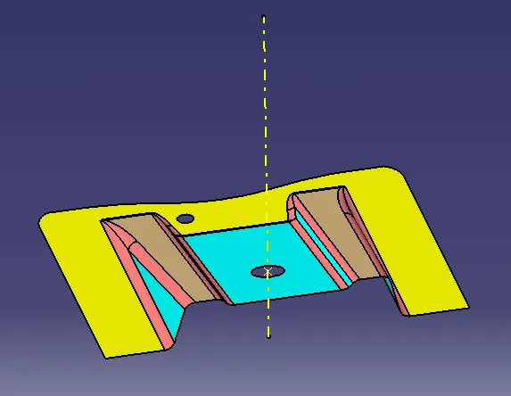
Tooling axis creation:
Then analyze all surfaces for the possibility of tooling clearing all surfaces.
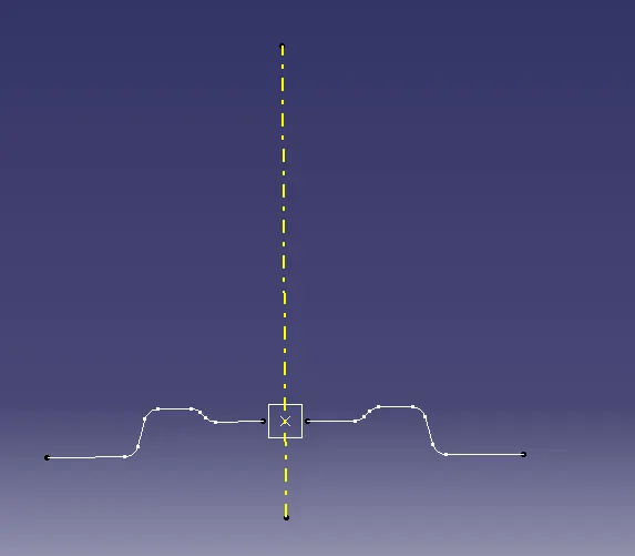
It seems that X direction does not create any error. So let’s consider the Y axis.
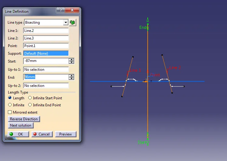
The two lines are created with the help of walls from the intersection created. Tooling axis created with the help of bisecting line passing from a point to the two lines.
Draft Analysis:
To perform draft analysis on the model: go to Menu bar > Analysis > Feature Draft analysis. We have to select customize the material mode under the shading option.
For draft analysis, the surface model and tooling axis are the inputs. For easy to remove parts from mold, the minimum draft angle is 3 degrees.
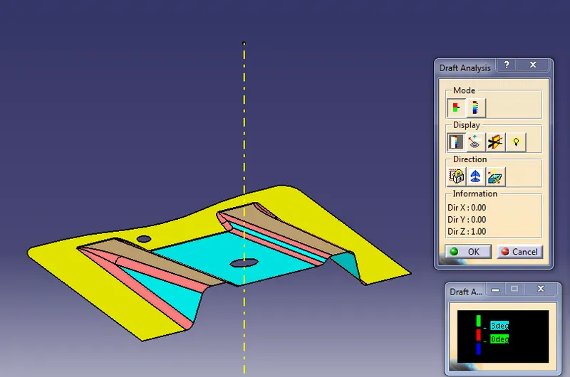
Compass will be used to determine the draft direction
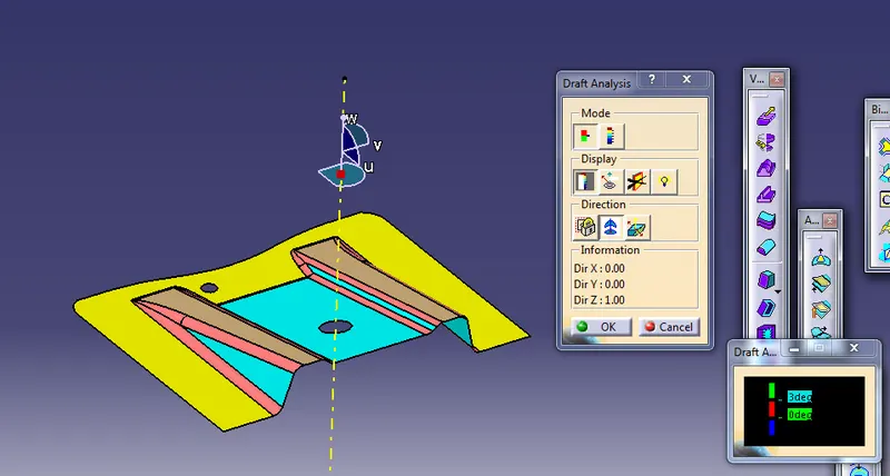
After placing the compass, select lock and then select part for start analysis.
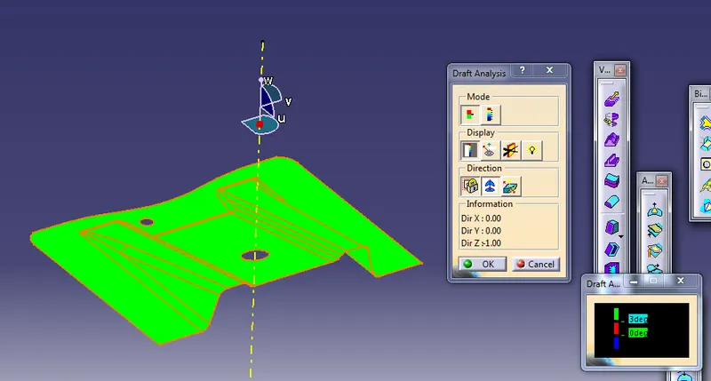
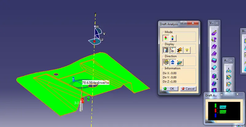
Minimum or more then 3 degree draft angle is provided in the surface model, So it shows Green in color. In the Draft Analysis box more than 3 degrees is Green, Zero degree is in Red and Negative is in Blue.
Class-B Surface creation:
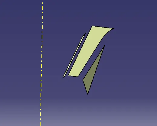
For creation of class B surface, 1st starts doing from ribs. We have to extract (With no propagation), and follow next operation as are untrim, extrapolate, trim and offset (As per given part thickness) & change colour into Green. Perform the same procedure for each surface and name as per features, Like Rib 1, Rib 2, Base Surface.
Extract:
Untrim:
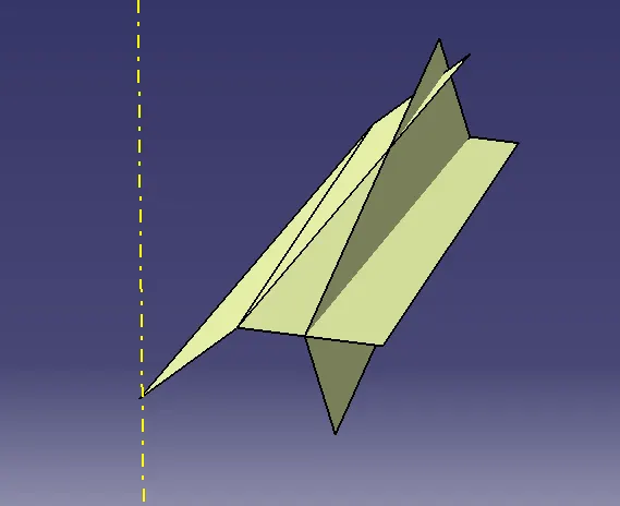
Extrapolate:
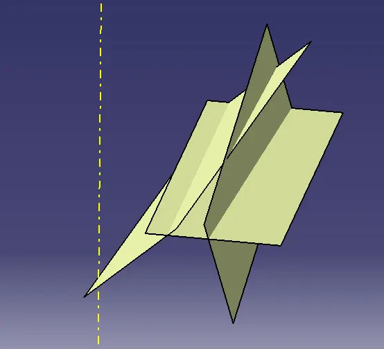
Trim:
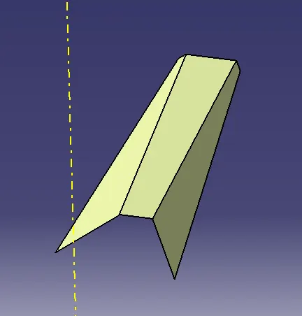
Offest:
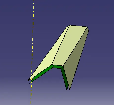
After allseparate separate feature are created, We have to trim with each other
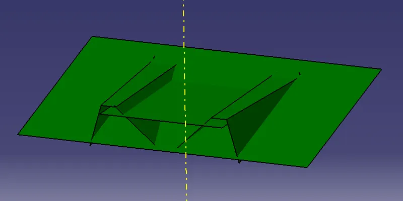
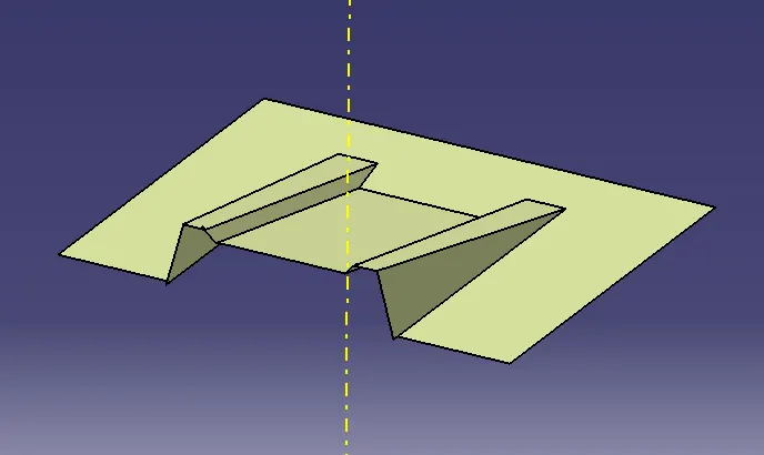
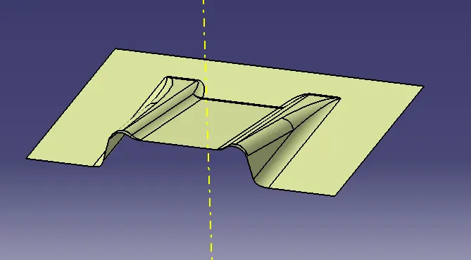
Now we will applied required radius(Class A surface radius value plus part thickness) as required corners.
Then we get the B surface.
Class C Surface creation:
First get all edges by boundary command.
Then perform the swept command with profile type Line and sub-type With draft direction, Input- Edges as Curve and Tooling direction as direction with 3 degree draft angle. Same process did with two holes as well.
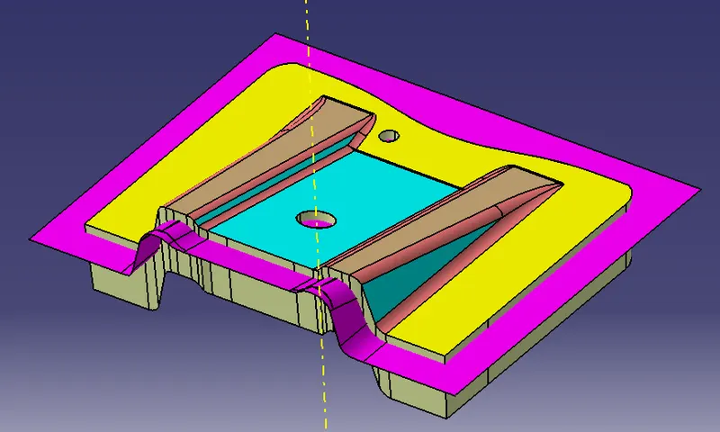
Then join Surface A and C (3 nos) together.
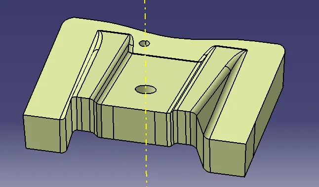
FINAL COMPONENT OUTPUT:
Now perform trim command with Surface A & C with Surface B.
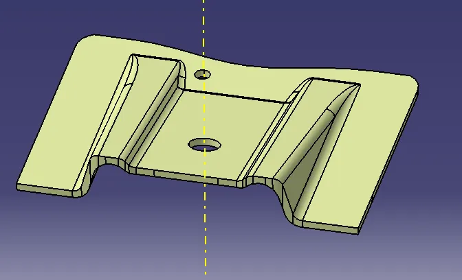
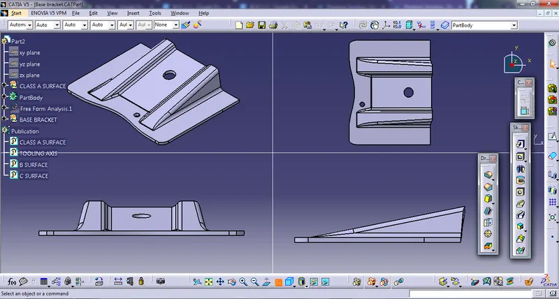
FINAL OUTPUT:
Finally in the part design environment and used close surface command to get the final part in solid.
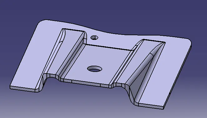
PUBLICATION:
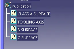
Publication of Class A surface, Tooling axis, B surface and C surface.