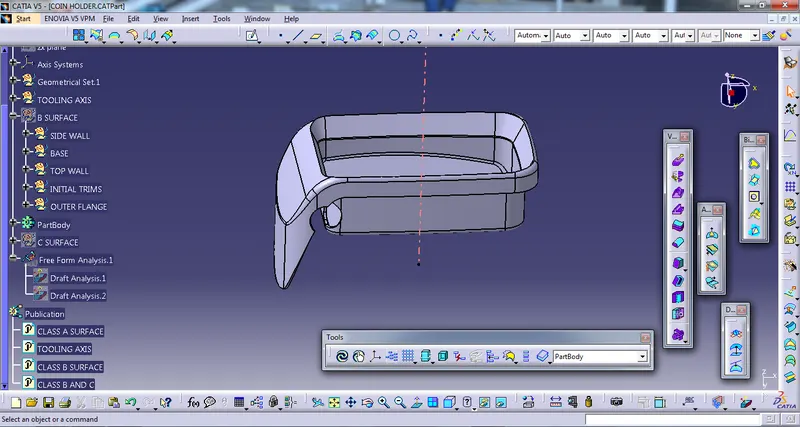
Week 8 - Challenge 4 - Coin Holder Design
COIN HOLDER DESIGN
AIM:
Perform draft analysis of given class A surface of coin holder catia model and creation of Class B & Class C surface creation to get solid part out of it. Again perform draft analysis of output solid component.With considering part thickness is 2.5mm.
OBJECTIVE:
Ensure proper tree structure
Ensure proper names for every geometrical set according to sketches.
All sketches should be under the geometrical set.
Publication of tooling axis and class A, B and C surface.
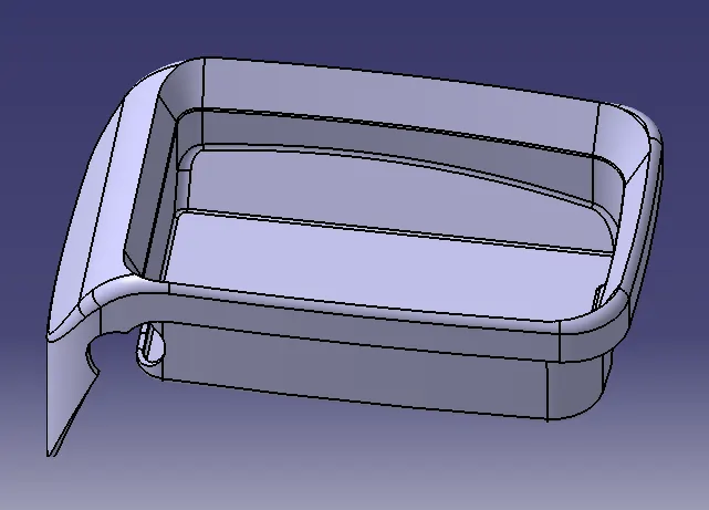
Provided Class A surface after import in CATIA.
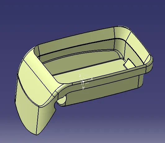
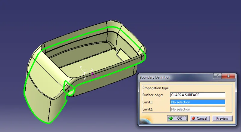
1st we have to check the connectivity of the surface.whether the surface provided has any discontinuity in it. It will be done by creating a boundary or by using the joining command.
TOOLING AXIS CREATION:
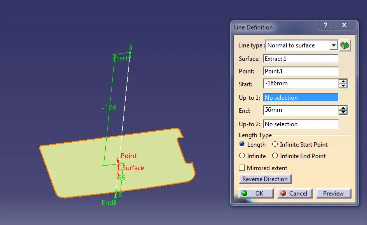
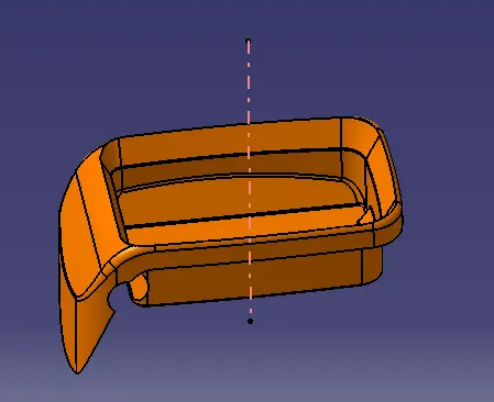
Analyze all surfaces for the possibility of tooling clearing all surfaces. For this type of construction surface it’s required to have side-core action to get proper features and be easy to ejection. So we need two tooling axis directions, One is the main tooling direction normal to base surface and side-core tooling direction to clearing the hole feature.
Simply extract the base surface and create a point on the center of the surface. Then draw a line normal to the surface.
DRAFT ANALYSIS:
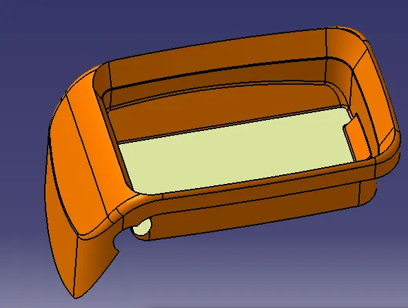
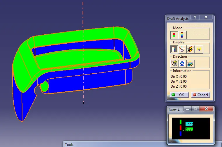
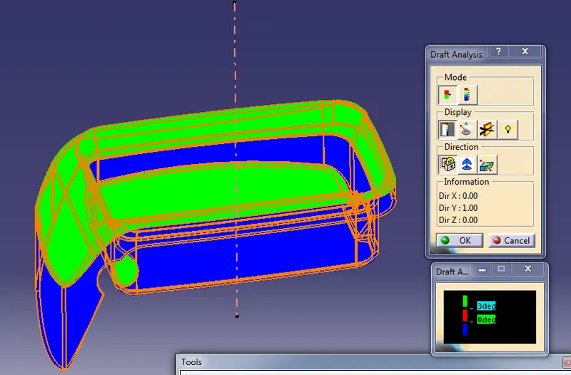
To perform draft analysis on the model: go to Menu bar > Analysis > Feature Draft analysis. We have to select customize the material mode under the shading option.
For draft analysis, the surface model and tooling axis are the inputs. For easy to remove parts from mold, the minimum draft angle is 3 degrees.
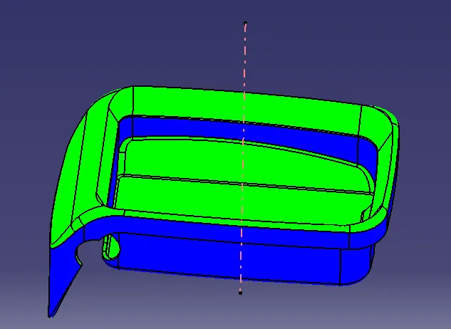
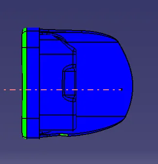
Minimum or more then 3 degree draft angle is provided in the surface model, So it shows Green in color. In the Draft Analysis box more than 3 degrees is Green, Zero degree is in Red and Negative is in Blue.
B SURFACE CREATION:
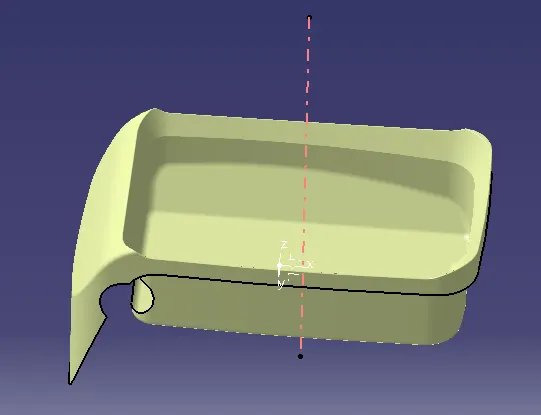
At first we extract all surfaces excluding the filets. While performing this operation we should group the different walls of the A surface for easy access, (In case if some modification required).
Starting from the base surface, side wall, top wall and outer flange. At last we perform all trims and fillet to get the final output of the class B surface.
C SURFACE CREATION:
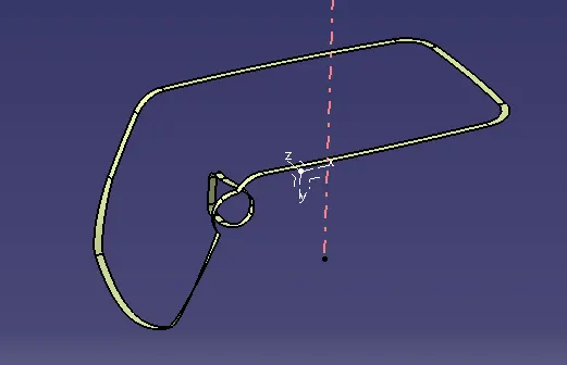
First we have to extract all edges of class A surface, then surrounding surfaces as well. To form C surface we use sweep command with reference surface with angle 90 degree. Same method followed for the hole area as well to create the C surface.
FINAL COMPONENT IN SURFACE:
Now perform join commane taking input as Class C and A surface.
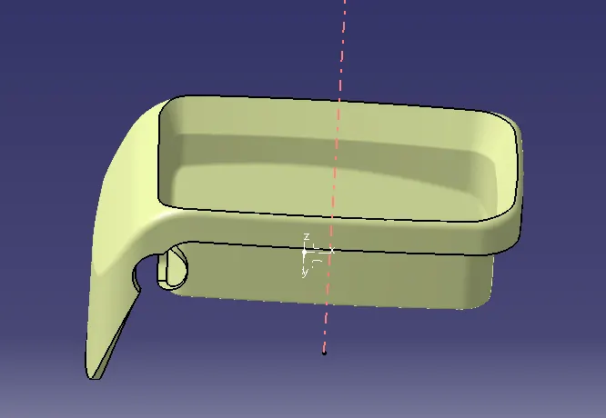
Then do trim with the class B surface.
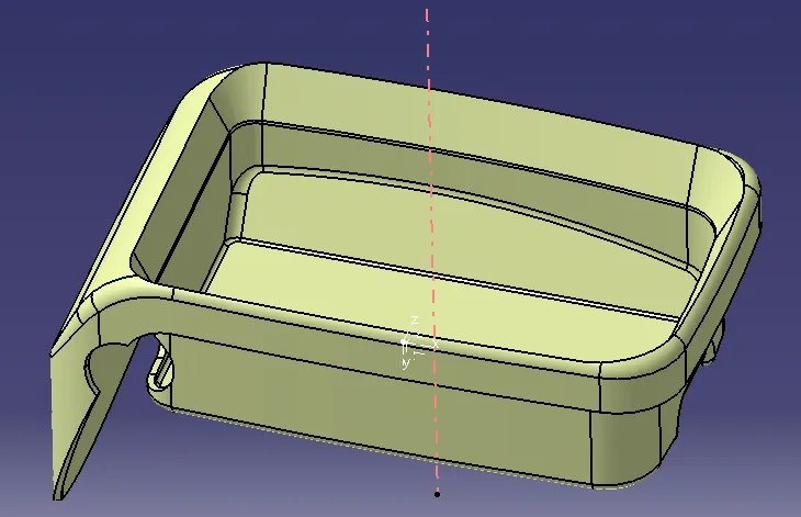
FINAL OUTPUT COMPONENT:
By using the Closed surface tool we get the final component in solid.
DRAFT ANALYSIS OF FINAL COMPONENT:
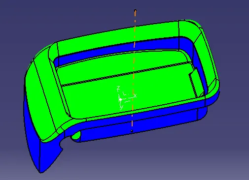
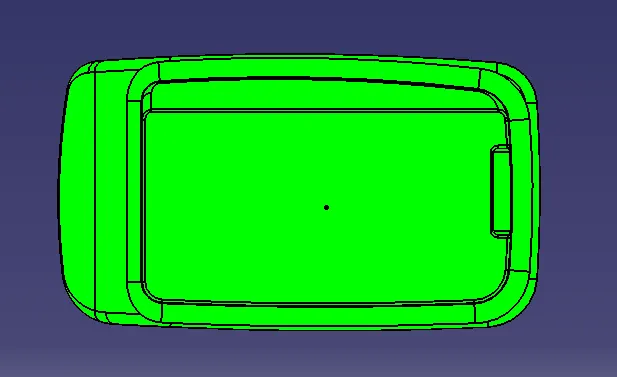
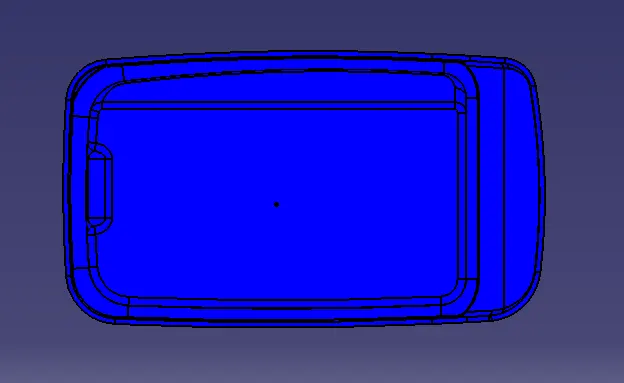
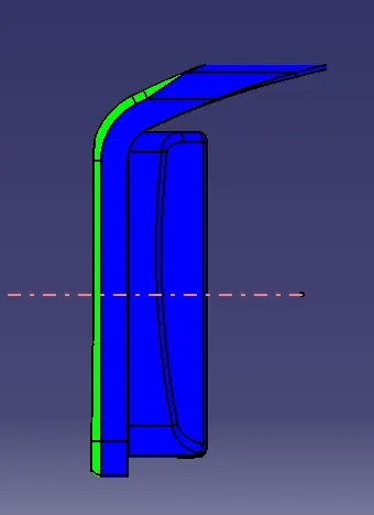
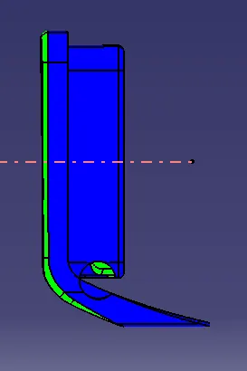
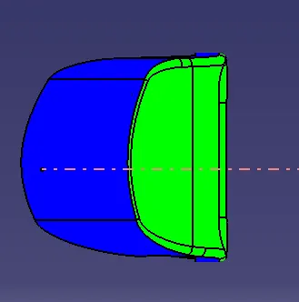
Minimum or more then 3 degree draft angle is provided in the surface model, So it shows Green in color. In the Draft Analysis box more than 3 degrees is Green, Zero degree is in Red and Negative is in Blue.
TREE STRUCTURE: