Project 1 - Door Applique Design with Engineering Features using CATIA V5.
AIM: To create a plastic design and attach the Engineering features and generate the Draft Analysis for the given Door Applique Class A model.
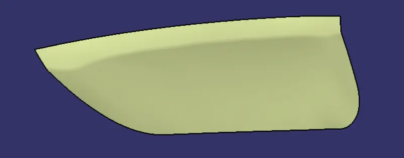
Door Applique.
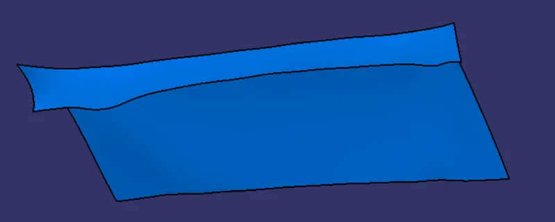
Door Attachment Surface.
OBJECTIVES:
- Create a Door Applique Plastic component with the given Class-A surface, also create Heat Stakes and Locators considering the Design Rules.
- Use Positioned sketches and the Sketches should be Iso-Constrained.
- To ensure proper tree structure is followed.
- Geometrical sets should have a proper name based on the sketches present inside of them.
- All the sketches should be created under the geometrical set.
- A detailed report should be done explaining the draft analysis and the tooling axis creation.
- An explanation should be given on the way of creating the tooling axis, particularly the Bisecting method.
THEORY:
- Draft Analysis:
Draft analysis helps to detect if your drafted part is easily removable from the mould (in case of plastic component) or die (in case of sheet metal). All plastic components will have a minimum draft of 0.5 to 3deg. And for automotive sheet metal parts, the draft will be 7deg or more. If a mould wall is perpendicular to the part ejection, there is ample friction or interference between the mould and the part which will not allow one to release from the other. This is why design engineers give a minimum draft to the part.
In CATIA V5 the feature draft analysis dialogue box looks like this:
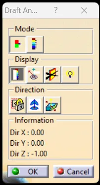
- Mode:
- The mode option let you choose between quick analysis and full analysis mode.
- In quick mode, there are 3 ranges blue, red and green colours. In the case of the plastic component, we will set the draft angle as 3°.
2. Display:
- The first box is to open and close the colour scale dialogue box.
- The second box is the analysis under the running point when activating the checkbOx and moving the pointer over the surface. This option enables you to perform local analysis. Arrows are displayed under the pointer, identifying the normal to the surface at the pointer location (green arrow), the draft direction (red arrow), and the tangent (blue arrow). As you move the pointer over the surface, the display is dynamically updated. Furthermore, circles are displayed indicating the plane is tangent to the surface at this point. The displayed value indicates the angle between the draft direction and the tangent to the surface at the current point.
- Click the No Highlight Representations button to set the display option of highlight effect sources as 'on/off. When checked 'On" the surfaces are selected but they will not be seen in the specification tree.
- Click the Light Effect button and the colours of the analyzed elements react to the light source.
3. Direction:
- The first check box is the locked direction icon which is used to lock the direction of the compass after selecting the specified direction.
- Click on the compass icon to specify the new pulling direction to remove the part.
- Click the Inverse button to automatically reverse the draft direction. When several elements are selected for analysis, the draft direction is inverted for each element when the button is clicked.
- Tooling Direction:
The Tooling Direction is the direction that the mould pulls apart. The mould is built into two separate pieces. You have a Cavity side and you have the Core side. The Core pulls apart from the Cavity and that's the Dyeline or the Tooling Direction. There are different methods to find out the tooling direction. Here we are using bisecting method to find out the tooling direction. We can use any method the ultimate aim is to reduce the cost of manufacturing by reducing the complicity in manufacturing the component.
- Heat Staking:
Heat Staking is a pulsed heat process to join two or more parts out of which one at least is made of plastics. The process is to deform the plastic material using heat force at a set process time. The bond is made by partially de-forming the plastic parts to fix the other.
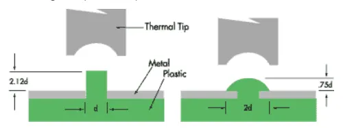
Heat Staking makes it easy to bond metak to plastics and is commonly used in high volume and low-cost applications such as Automotives and consumer appliances. In the manufacturing of thermoplastic components, it is often necessary to join the thermoplastics to a part of dissimilar material whether it can be a metal, dissimilar material or other materials. Thermal staking is an assembly method that uses the controlled melting and reforming of plastic studs or bosses to capture or lock another plastic or a metal component of an assembly in place.
Advantages of Heat Stakes:
- Similar and Dissimilar materials may be joined: metal to metal, plastics to plastics, metal to plastics.
- Local heating results in no damage to surrounding materials.
- Accurate control operating within a small process window.
- No mechanical Vibration.
- Processing of glass-filled materials.
- 4 and 2 Way Locators:
- Locators are used to locating a job or a component to rest its degrees of freedom using the 3-2-1 Principle which is arresting 3 DOFs first then 2 DOFs and DOF in a sequence.
- A 4-Way Locator will look like a "+" and a 2-Way Locator will look like a "-".
- Both these locators used the same Rib Design Rules and principles.
- These locators are placed on the B side of the component and must have the same height concerning the B Surface.
- Fixture Design Rules:
- For a fixture designer, the major portion of design time is spent deciding how to locate the workpiece in the fixture.
- You know that any free body has a total of Twelve degrees of freedom as below:
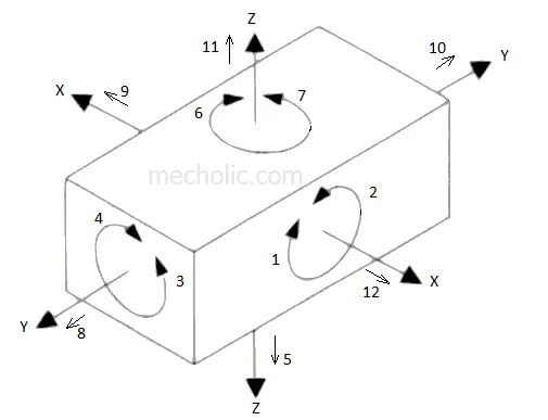
6 Translation Degree Of Freedom, +X,-X,+Y,-Y,+Z,-Z.
- Clockwise around X-Axis.
- Anticlockwise around X-Axis.
- Clockwise around Y-Axis.
- Anticlockwise around Y-Axis.
- Clockwise around Z-Axis.
- Anticlockwise around Z-Axis.
You must fix all the 12 Degree of freedom except the three transitional degrees of freedom(-X.-Y,-Z). to locate the workpiece in the fixture.
The Jig and fixture are tools used for holding the workpiece in a correct location for mass production, Various type of fixtures are used in the industry. The 3-2-1 Method is the fundamental principle for all types of fixture design.
PROCEDURE:
- Step 1: Determine Tooling Axis.
- Let's make a point on the Class A Surface of the Door Applique.
- Now using this point we will make the required Tooling Axis along the Y-Axis.
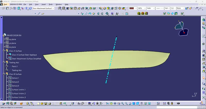
Figure1: The required Tooling Axis for the Door Applique.
- Step 2: Draft Analysis of Class A Surfaces:
- The Draft Analysis of the Class A Surfaces of Door is shown below the components are safe.
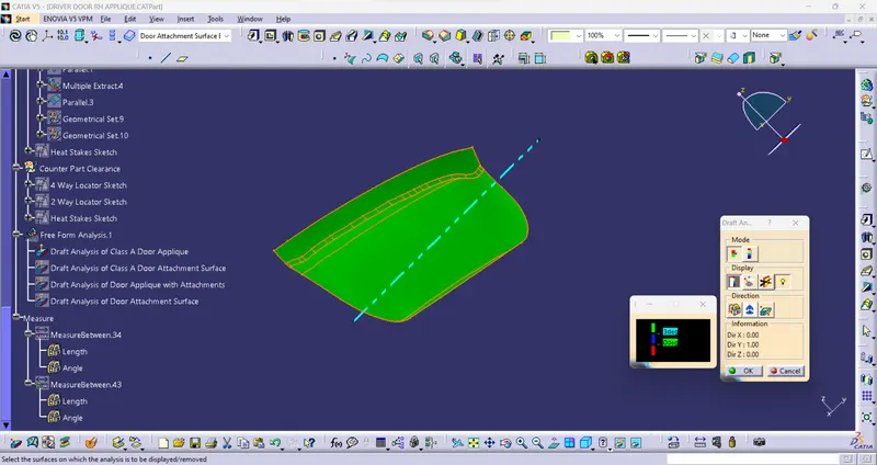
Figure2: Screenshot of Draft Analysis of Class A Surface of Door Applique.
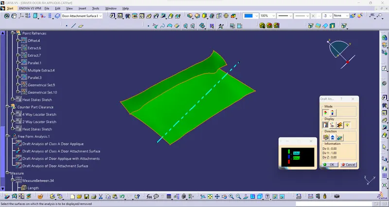
Figure3: Screenshot of Draft Analysis of Class A Surface of Door Attachment Surface.
- Step 3: Creating Class B Surface of Door Applique:
- Let's start by Extracting the 3 required surfaces of the Class A Surface.
- Now we will perform the Untrim operation on them.
- After the Untrim we will Offset these surfaces to a distance of 2.5mm.
- Now we will join the 1st and the 2nd Offset and Trim the output Join with the Offset 3.
- We will Extrapolate this Trim output and give it the required Fillet value.
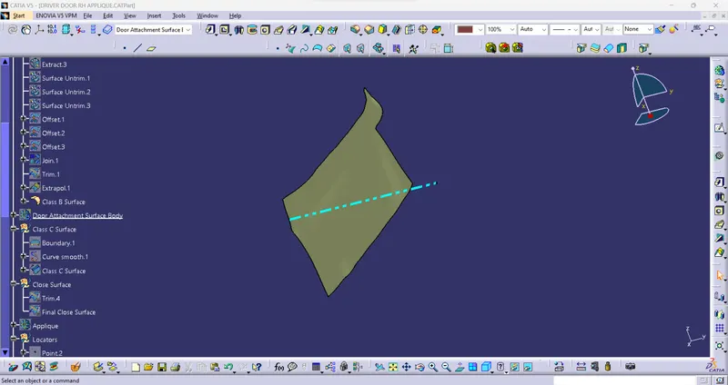
Figure4: Final Class B Surface of Door Applique after the above operations.
- Step 4: Creating Class C Surface of Door Applique:
- Now for the Class C Surface of the Door Applique, we need to take the Boundary of the Class A Surface of the Door Applique.
- Then we need to do the Smooth Curve operation on it so that the Sweep output will have proper curvature.
- Now at last we will create the required Sweep Operation for the C Surface that we need. Sweep > Profile Type : Line > Subtype : With Draft Direction > Guide Curve : Smooth Curve > Draft Direction : Tooling Axis > Angle : 3deg > Length : 20mm.
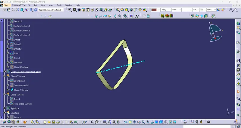
Figure5: Final Class C Surface of Door Applique after the above operations.
- Step 5: Creating the Close Surface of Door Applique:
- Now for the Close Surface of the Door Applique, we need to Trim the Class A Surface of the Door Applique with the Class C Surface of Door Applique.
- Then we need to do Trim the Class B Surface with Trim Output of Class A and Class C Surface.
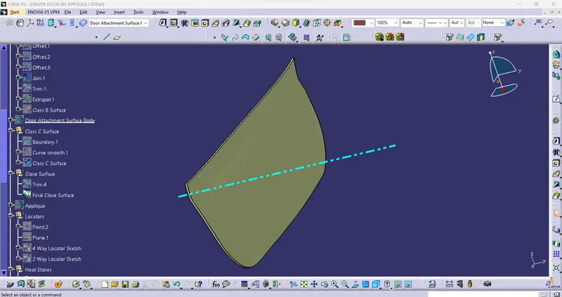
Figure6: Final Close Surface of Door Applique after the above operations.
- Step 6: Creating the Close Surface Body of Door Applique:
- Now for the Close Surface Body of the Door Applique, we need need to go to the Part Design workbench and use the Close Surface Tool on the Close Surface of the Door Applique.
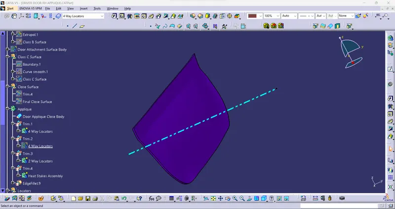
Figure7: Final Close Surface Body of Door Applique after the above operations.
- Step 7: Creating Locators for Door Applique:
- Sketches:
- First, we will start by making a point and a plane on the Door Applique Body.
- Now we will make a Sketch as mentioned below, the below Sketch is for 4-Way Locators.
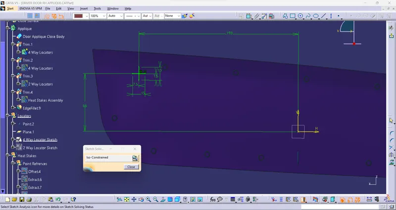
Figure8: Final Sketch of the 4-Way Locator of Door Applique.
- We also need to make a 2-Way Connector, below shows the Sketch for the 2-Way Locators.
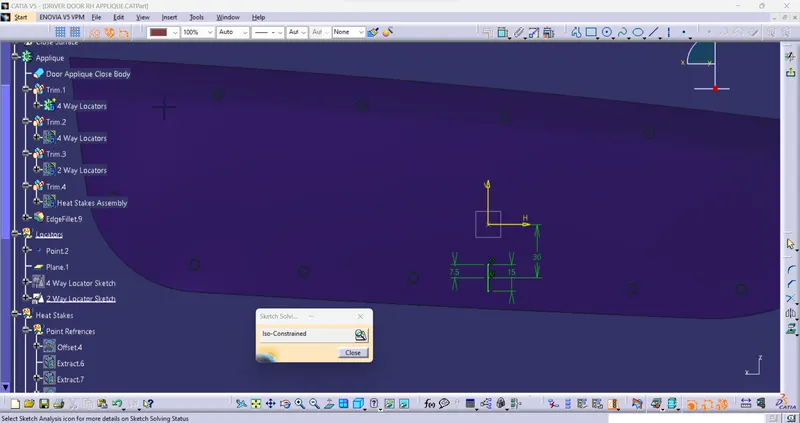
Figure9: Final Sketch of the 2-Way Locator of Door Applique.
- Body:
- Firstly we will create a body and Pad the 4-Way Locator Sketch to a required Height, and make it thick with a Thickness value of 1.3mm with the Neutral Fiber option turned on.
- Then we will give 0.5deg Draft to the Padded 4-Way Locator.
- On the top 4 edges, we will give the Chamfer of 3mm and 3mm Fillet to the Chamfered edge.
- We also need to give an overall Fillet of 0.3mm all over the 4-Way Locator.
- As we need one more 4-Way Locator we will copy this body of the 4-Way Locator and Paste it as Paste Special. Then will use the Translate feature to move the 2nd 4-Way Locator to the required position.
- Now that the Locators are ready let's use the Boolean Trim operation and Join the 4-Way Locators with the Door Applique Body.
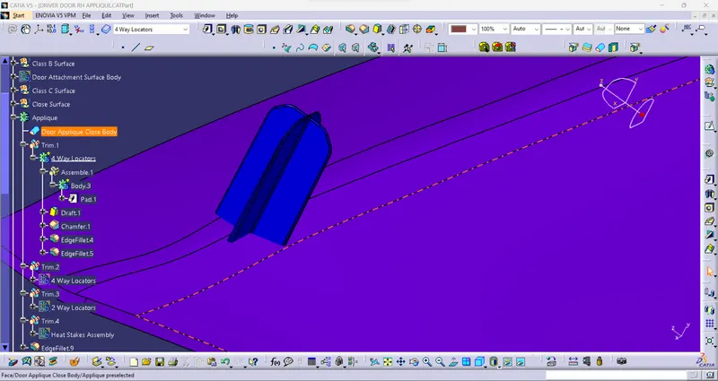
Figure10: Final Body of the 4-Way Locator of Door Applique after the above operations.
- Now for the 2-Way Locator, we will also create a body and Pad the 2-Way Locator Sketch to a required Height, and make it thick with a Thickness value of 1.3mm with the Neutral Fiber option turned on.
- Then we will give 0.5deg Draft to the Padded 2-Way Locator.
- On the top 2 edges, we will give the Chamfer of 3mm and 3mm Fillet to the Chamfered edge.
- We also need to give an overall Fillet of 0.3mm all over the 2-Way Locator.
- Now that the Locators are ready let's use the Boolean Trim operation and Join the 2-Way Locators with the Door Applique Body.
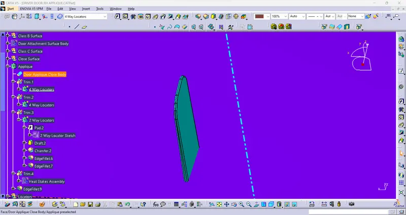
Figure11: Final Body of the 2-Way Locator of Door Applique after the above operations.
- Step 8: Creating Heat Stakes for Door Applique:
- For Point References:
- Let's start by offsetting the Class A Surface to 2.5mm, we will Extract the required face and Upper Boundary from the Class A Surface.
- For the bottom side of the Boundary, we will create it with the help of Multiple Extract.
- Now that we have the Upper and Lower boundary curves let's use the Parallel Curve Tool to offset the Curves to a 15mm inside.
- Now we will use the Points Repetition Tool to make multiple points on the offset Parallel Curve. We will make a total of 12 points as we are going to make 12 Heat Stakes.
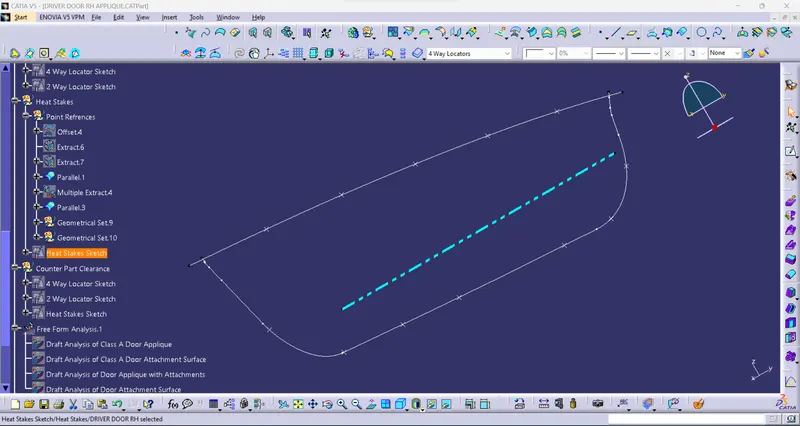
Figure12: 12 Points made after the above operations for the designing of Heat Stakes.
- Now that we have the points let's make the Sketch for the Heat Stakes.
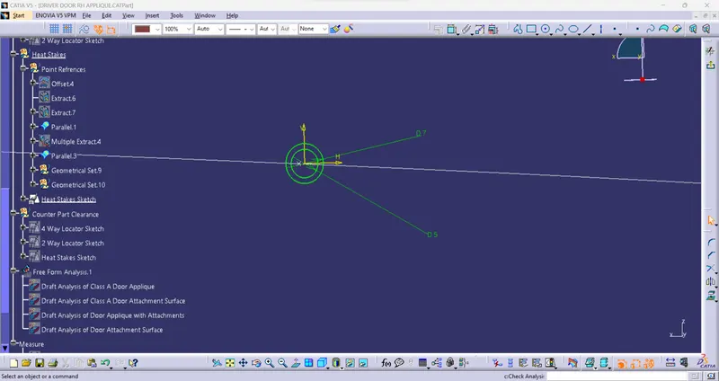
Figure13: Final Sketch of the Heat Stakes of Door Applique.
- Body:
- Firstly we will create a body and Pad the Heat Stakes Sketch to a required Height.
- Then we will give 0.5deg Draft to the Padded Heat Stakes.
- We also need to give an overall Fillet of 0.3mm all over the 4-Way Locator.
- As we need 11 more Heat Stakes we will copy this body of the Heat Stakes and Paste it as Paste Special. Then will use the Translate feature to move the body to the points we have created.
- Now that all the Heat Stakes are created let's use the Boolean Trim operation and Join the Heat Stakes with the Door Applique Body.
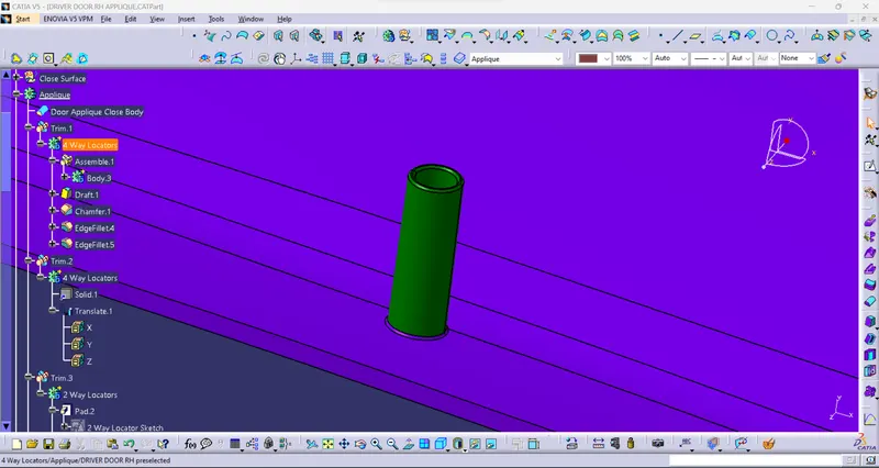
Figure14: Final Body of the Heat Stakes of Door Applique after the above operations.
- Step 9: Draft Analysis of Door Applique with Attachments:
- The Draft Analysis of the Door Applique with Attachments Body is shown below the components are safe.
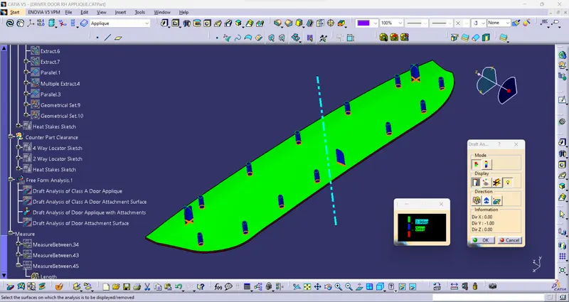
Figure15: Screenshot of Draft Analysis of Door Applique with Attachment Body.
- Step 10: Creating the Close Surface Body for Door Attachment Surface:
- Now for the Close Surface Body of the Door Attachment Surface, we need need to Thicken the Class A Surface of the Door Attachment Surface to do that we need to go to the Part Design workbench and use the Thick Surface Tool on the Class A Surface of the Door Attachment.
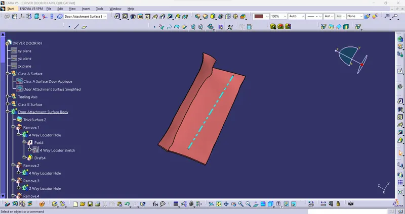
Figure16: Final Thick Surface Body of Door Attachment after the above operations.
- Step 11: Creating Counter Part Clearance of the Locators for Door Attachment:
- Sketches:
- We will copy the sketch we made for the 4-Way Locator and modify the sketch as required.
- For the 4-Way Locators, it is accepted to have a clearance of 0.1mm from every side.
- Keeping this in mind we will modify the sketch to the circle of 15.1mm for the 4-Way Locator.
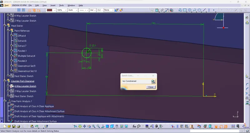
Figure17: Final Sketch of the 4-Way Locator Clearance of Door Attachment.
- We also need to make Clearance for the 2-Way Connector so we will copy the sketch we made for the 2-Way Locator and modify the sketch as required.
- For the 2-Way Locators, it is accepted to have a clearance of 0.1mm from every side.
- Keeping this in mind we will modify the sketch to the circle of 15mm for the 2-Way Locator.
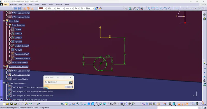
Figure18: Final Sketch of the 2-Way Locator Clearance of Door Attachment.
- Body:
- Firstly we will create a body and Pad the 4-Way Locator Clearance Sketch.
- Then we will give 0.5deg Draft to the Pad.
- Now that the Locators Holes are ready let's use the Boolean Remove operation and Join the 4-Way Locators Pad with the Door Attachment Body.
- As we have one more 4-Way Locator we need to make a Clearance Hole for that too so will copy this body of the 4-Way Locator Pad and Paste it as Paste Special. Then will use the Translate feature to move the 2nd 4-Way Locator Pad to the required position.
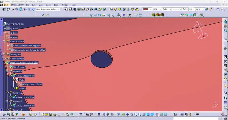
Figure19: Final look of the 4-Way Locator Clearance Hole on the Door Attachment after the above operations.
- Now for the 2-Way Locator, we will also create a body and Pad the 2-Way Locator Clearance Sketch.
- Then we will give 0.5deg Draft to the Pad.
- Now that the Locators Holes are ready let's use the Boolean Remove operation and Join the 2-Way Locators Pad with the Door Attachment Body.
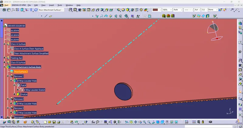
Figure20: Final look of the 2-Way Locator Clearance Hole on the Door Attachment after the above operations.
- Measurements of the Clearance Hole:
- Let's measure to make sure we have made the Clearance Hole with the required clearance as per the Design Rules.
- Take Measurement for the 4-Way Locator with the Clearance Hole.
- The measurement of the Clearance Hole and the 4-Way Locator is around 0.12mm which is acceptable.
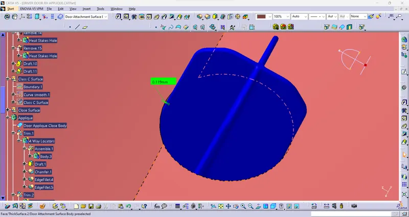
Figure21: Measurement of the 4-Way Locator with the Clearance Hole.
- Now take the same Measurement for the 2-Way Locator with the Clearance Hole.
- The measurement of the Clearance Hole and the 2-Way Locator is around 0.09mm which is acceptable.
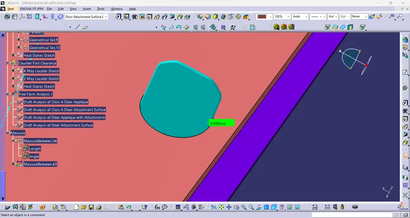
Figure22: Measurement of the 2-Way Locator with the Clearance Hole.
- Step 12: Creating Counter Part Clearance of the Heat Stakes for Door Attachment:
- Sketches:
- We will copy the sketch we made for the Heat Stakes and modify the sketch as required.
- For the Heat Stakes, it is accepted to have a clearance of 0.5mm from the side.
- Keeping this in mind we will modify the sketch to the circle of 8mm for the Heat Stakes.
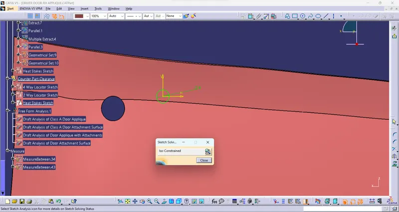
Figure23: Final Sketch of the Heat Stakes Clearance of Door Attachment.
- Body:
- Firstly we will create a body and Pad the Heat Stakes.
- Then we will give 0.5deg Draft to the Pad.
- Now that the Heat Stakes Holes are ready let's use the Boolean Remove operation and Join the Heat Stakes with the Door Attachment Body.
- As we have 11 more Heat Stakes we need to make a Clearance Hole for that too so will copy this body of the Heat Stakes Pad and Paste it as Paste Special. Then will use the Translate feature to move all the 11 Heat Stakes Pad to the required position.
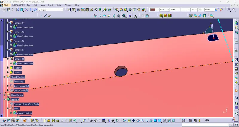
Figure24: Final look of the Heat Stakes Clearance Hole on the Door Attachment after the above operations.
- Measurements of the Clearance Hole:
- Let's measure to make sure we have made the Clearance Hole with the required clearance as per the Design Rules.
- Take Measurement for the Heat Stakes with the Clearance Hole.
- The measurement of the Clearance Hole and the Heat Stakes is around 0.5mm which is acceptable.
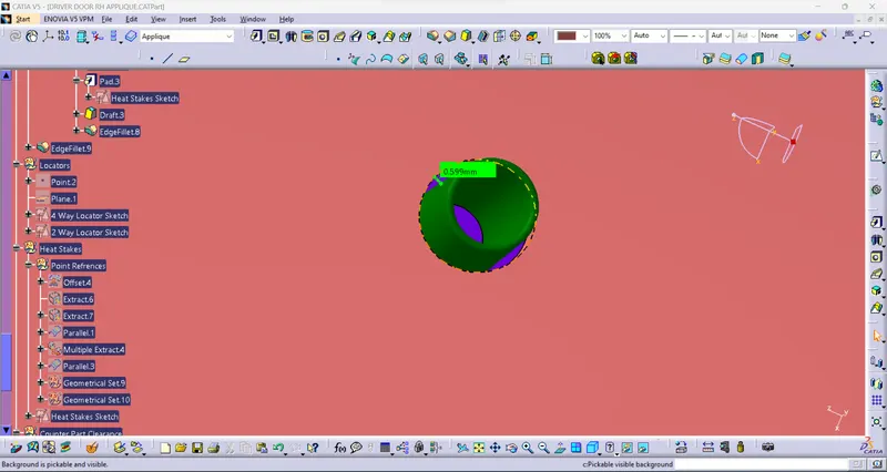
Figure25: Measurement of the Heat Stakes with the Clearance Hole.
- Step 13: Draft Analysis of Door Attachments with Clearance Hole:
- The Draft Analysis of the Door Attachment with Clearance Hole Body is shown below the components are safe.
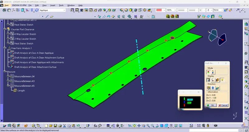
Figure26: Screenshot of Draft Analysis of Door Attachment with Clearance Body.
- Terms asked to Mention:
- Tree Structure:
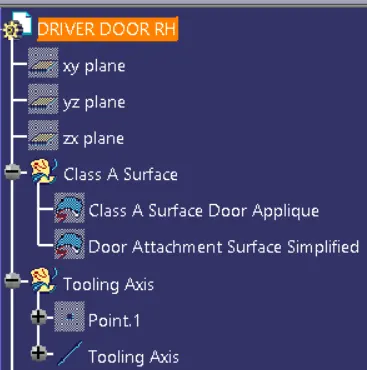
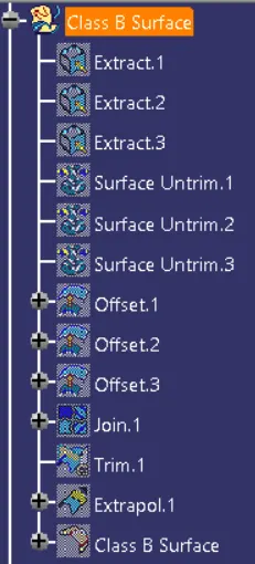
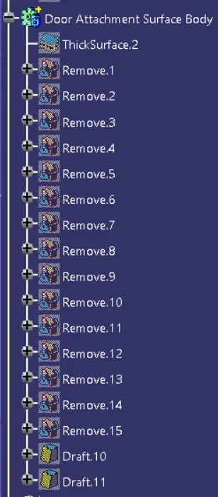
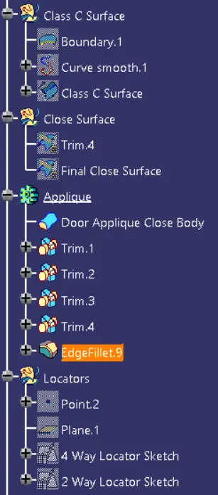
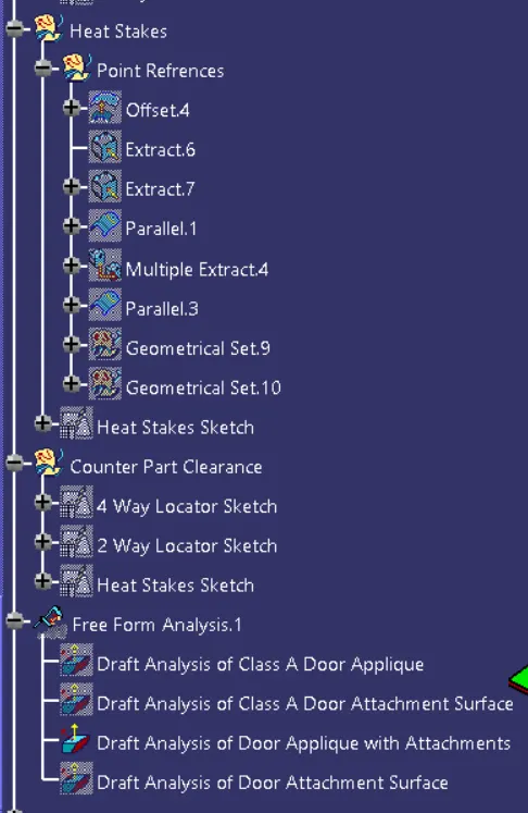
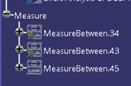
Figure27: Screenshots of Tree Structure of Driver Door RH Applique.
- Screenshots of the model with the proper colour code of the draft angle in various orientations (Isometric, Front, Side, and Top View):
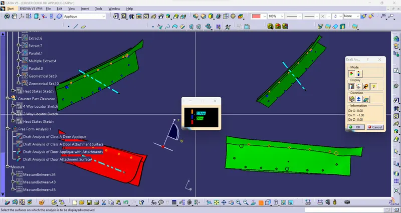
Figure28: Model in Various Views.
RESULT:
- Creation of Tooling Axis for Driver Door RH Applique.
Figure29: Result of creating Tooling Axis for Driver Door RH Applique.
- The Draft Analysis of the Class A Surfaces.
Figure30: Result of Draft Analysis of Class A Surface of Door Applique.
Figure31: Result of Draft Analysis of Class A Surface of Door Attachment Surface.
- Creating Class B Surface of Door Applique.
Figure32: Result of Class B Surface of Door Applique.
- Creating Class C Surface of Door Applique.
Figure33: Result of Class C Surface of Door Applique.
- Creating the Close Surface of Door Applique.
Figure34: Result of Close Surface of Door Applique.
- Creating the Close Surface Body
Figure35: Result of Close Surface Body of Door Applique.
- Creating Locators for Door Applique.
Figure36: Result of the 4-Way Locator of Door Applique.
Figure37: Result of the 2-Way Locator of Door Applique.
- Creating Heat Stakes for Door Applique.
Figure38: Result of the Heat Stakes of Door Applique.
- Draft Analysis of Door Applique with Attachments.
Figure39: Result of Draft Analysis of Door Applique with Attachment Body.
- Creating the Close Surface Body for Door Attachment Surface
Figure40: Result of Thick Surface Body of Door Attachment.
- Creating Counter Part Clearance of the Locators for Door Attachment.
Figure41: Result of the 4-Way Locator Clearance Hole on the Door Attachment.
Figure42: Result of the 2-Way Locator Clearance Hole on the Door Attachment.
Figure43: Result of Measurement of the 4-Way Locator with the Clearance Hole.
Figure44: Result of Measurement of the 2-Way Locator with the Clearance Hole.
- Creating Counter Part Clearance of the Heat Stakes for Door Attachment.
Figure45: Result of the Heat Stakes Clearance Hole on the Door Attachment.
Figure46: Result of Measurement of the Heat Stakes with the Clearance Hole.
- Draft Analysis of Door Attachments with Clearance Hole.
Figure47: Result of Draft Analysis of Door Attachment with Clearance Body.
CONCLUSION:
To Create Driver Side RH Door Applique Design with 4-Way Locator, 2-Way Locator and Heat Stakes have been completed by using Industrial principles and Design Rules and doing the Draft analysis on the given Class-A Surface and Final Complete Model.