Week 9 - Project 1 - Door Applique Design with Engineering Features
AIM:
To create Plastic design and attach the Engineering features and generate the Draft Analysis for the given Door Applique Class A model.
INTRODUCTION:
HEAT STAKING:
Heat Staking is a pulsed-heat process to join two or more parts out of which one at least is made of plastic. The process is to deform the plastic material using heat and force at a set process time. The bond is made by partially de-forming the plastic part in order to fix the other.
Heat Staking makes it easy to bond metal to plastic and is commonly used in high volume/low-cost applications such as automotive, IT and consumer appliances.
In Manufacturing Of thermoplastic components, it is often necessary to join the thermoplastic to a part of a dissimilar material, whether it can be a metal, dissimilar material or the other material. Thermal staking is an assembly method that uses the controlled melting and reforming of a plastic stud or boss to capture or lock another plastic or a metal component of an assembly in place. The plastic studs protrude through the holes in a component to be locked in a place. The heated thermal tip contacts the top of the stud, which melts and fills the volume of the tip cavity to produce the head, locking the component in a place. The progressive melting of the plastic under continuous pressure forms the head. When Staking, the right combination of heat and pressure for the applications is critical.
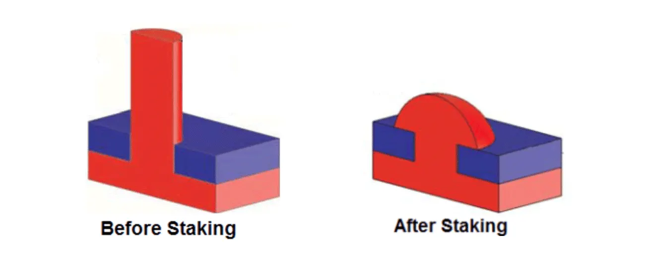
Advantages of Heat Stakes:
- Similar and dissimilar materials may be joined: metal to metal, plastic to plastic, metal to plastic.
- Accurate control operating within a small process window.
- Local heating resulting in no damage to surrounding materials.
- Processing of glass-filled materials.
- No mechanical vibration.
- Many heat-stake shapes possible through custom designed tools.
2 WAY AND 4 WAY LOCATORS:
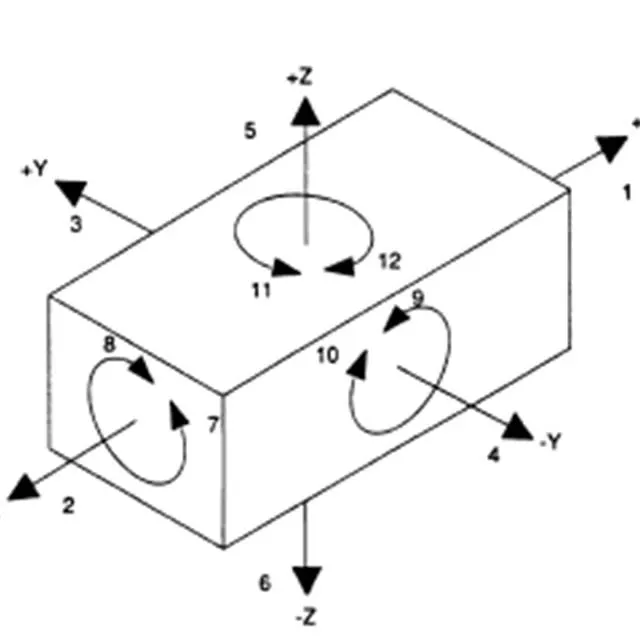
In any kind of assembly before fixing the part to the mating part we need to fix the position of the part with respect to the mating part. In these cases, we need to follow some engineering principles. In this project we are going to follow the 3-2-1 Principle. Any Part which has to be fixed during welding or machining process has to be fixed is having 12 degrees of freedom.
- Translation Movement along X Axis
- Translation Movement along Y Axis
- Translation Movement along Z Axis
- Rotational Movement along X Axis
- Rotational Movement along Y Axis
- Rotational Movement along Z Axis
Degrees of freedom:
PROCEDURES:
Tooling axis creation:
The tooling axis is the direction of drawing a sheet metal where the finished component is easily ejected on a particular direction and axis. The tooling axis is important for removing the material when finished.
- First, I will create An Axis system, from that axis system I will get two cross-sections. by using that cross-section lines I will create the tooling axis for the surface.
- Or, if it is a flat surface I will create a point using surface and create a line using the Axis system.
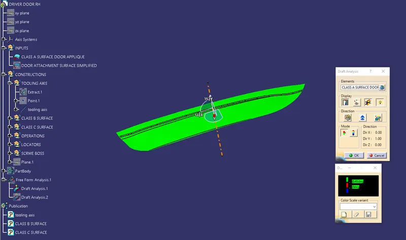
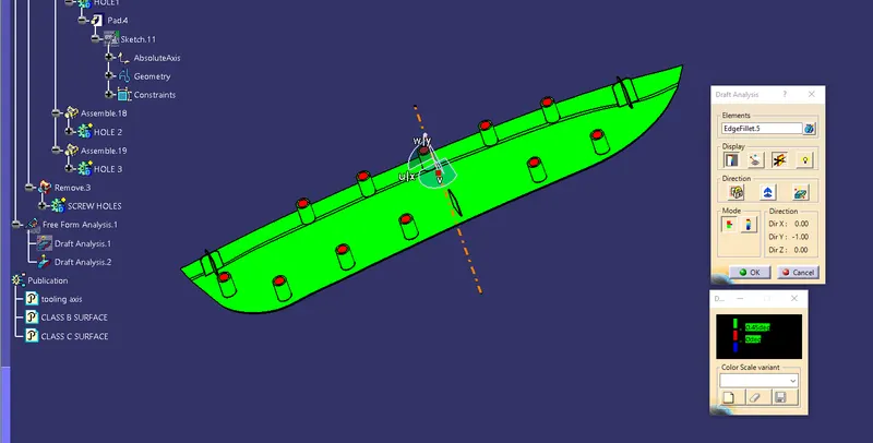
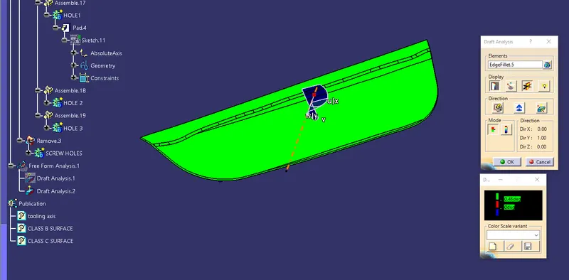
Now performing Draft analysis to check whether the tooling axis has some negative draft
CLASS A SURFACE:
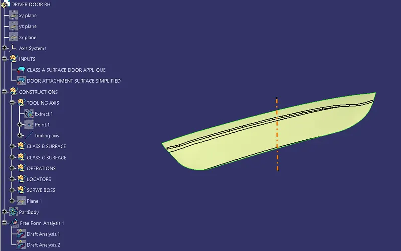
The asthetic part of class A surface which given.
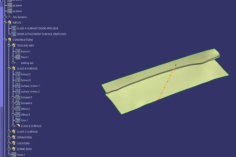
CLASS B SURFACE:
Extracting the class - A surface without the fillets and then trimming and extrapolating them to join them, and after that offset the surface to 2.5 mm thickness which forms as the Class - B surface.
CLASS C SURFACE:
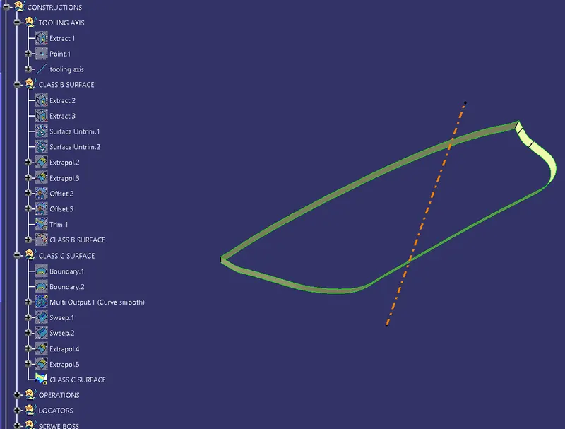
The C class surface will be created using the sweep command and for that, the Boundary lines are obtained from the A-class surface.The curve part is then smooth by some value for ease in sweeping.
Then, all boundary lines are sweep with draft direction since all the surfaces must have a draft angle of 3 degrees. Also, the tooling axis is used as the direction of the sweep.
FINAL JOINS:
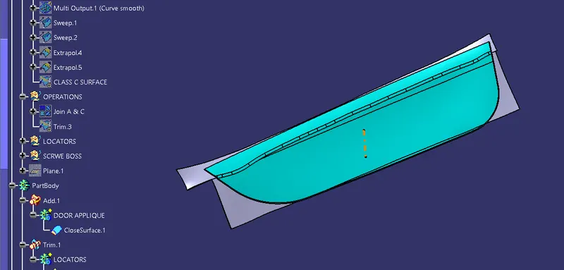
After finishing all the 3 surfaces, join the class A and class C surface together using the Join command.
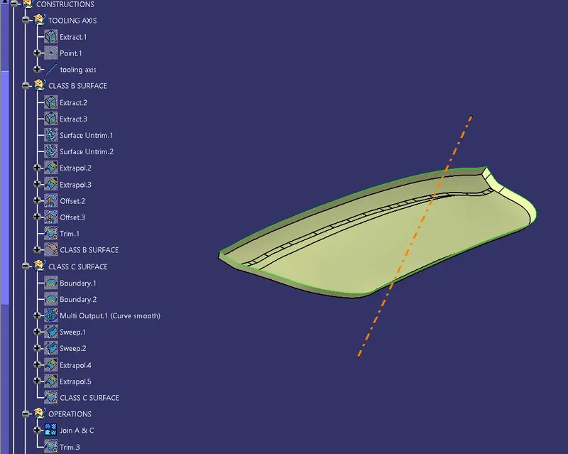
Now, the joined surfaces are then trimmed with class B surface to form a closed surface.
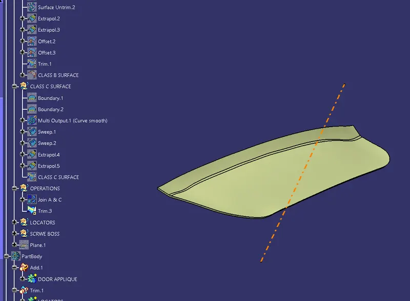
This is the part which changed to solid by using closesurface tool.
ATTACHMENT FEATURES:
2 WAY AND 4 WAY LOCATORS:
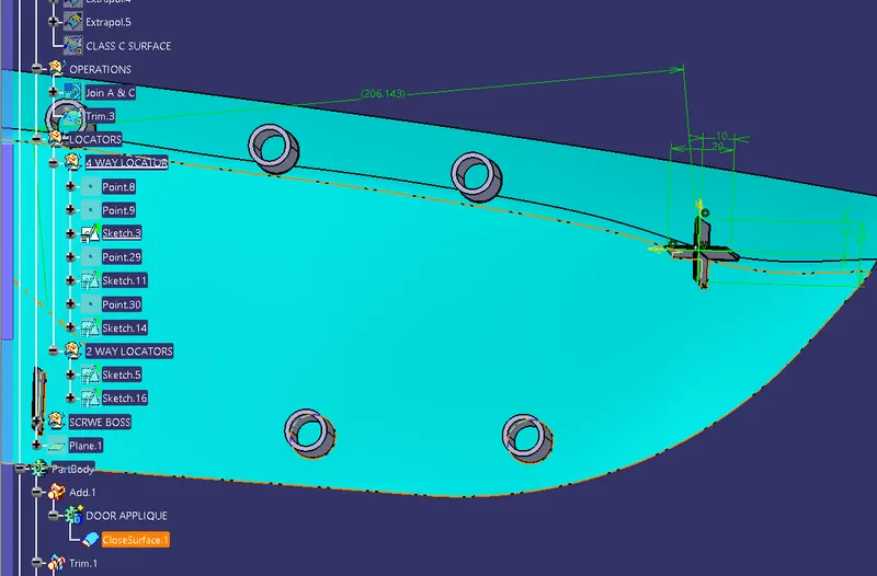
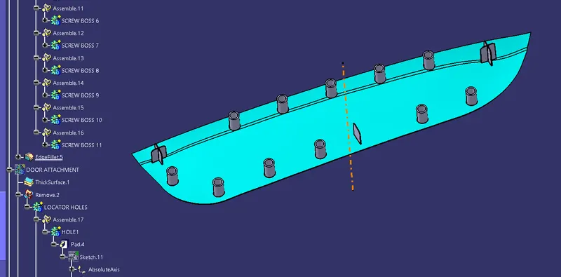
- To create 4 Way locators, the ribs should be created intersecting with each other.
- Open the Sketcher Workbench and Draw 2 lines intersecting each other and constraint it.
- Exit the Sketcher Workbench and Pad the Sketch with a thickness of 1.2 mm.
- Now, provide a draft of 0.5 degrees to the faces. Here the pulling direction is the tooling axis and the neutral face is the top face.
- Provide the chamfer of 3*45 to the edges of the locators.
- For the 2-way locators, only a single line needs to created and the rest procedure is the same as 4-way locators.
TRANSLATION:
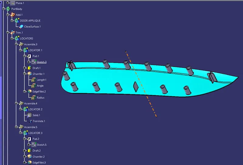
Translate the 4 way locator at required position.
HEAT STAKES:
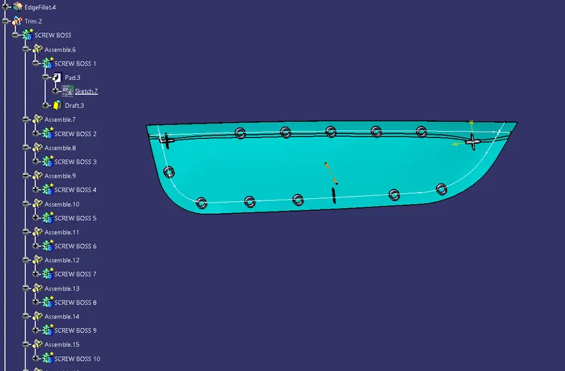
- To create the heat stakes, open the Sketcher Workbench and Draw 2 circles with the Diameter of 7 and 5 mm.
- Exit the Sketcher Workbench and Pad the Heat Stakes and draft it to 0.5 degrees.
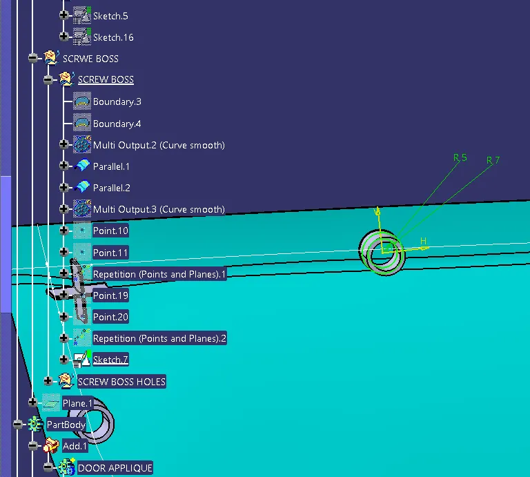
First, the boundary curve is extracted and then this curve is parallel to 15 mm.
Create the repetition of the points instances as required.
Now, copy the heat stakes and again paste it and then use translate by a point on this copied heat stakes.
Assemble all heat stakes into a body and later assemble them with the door applique.
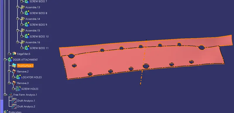
create the solid surface from attachment part using thickness command by 2.5 mm.
MAKING THE HOLES ON THE DOOR ATTACHMENT COMPONENT:
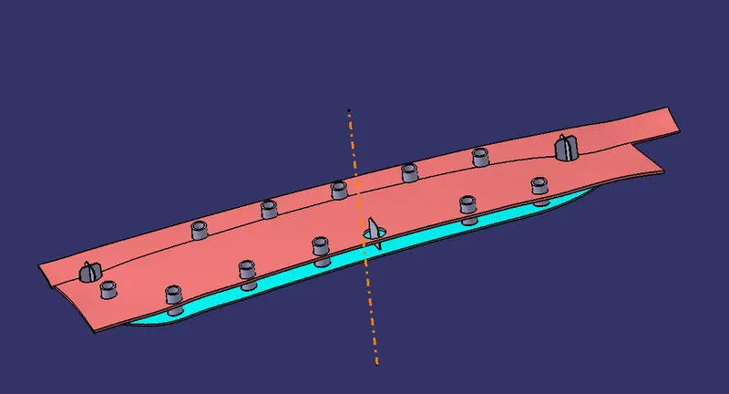
For the created Locators and Heat skates created, there should be holes created such that the component gets fixed in the Door attachment component constraining the Degrees of freedom.
The clearance with the near edges should be 0.1 for locators and 0.5 for heat stakes.
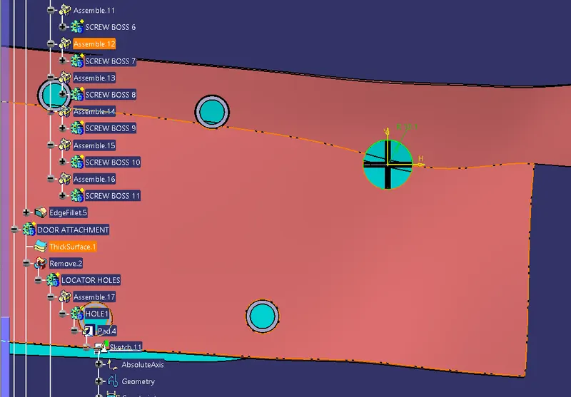
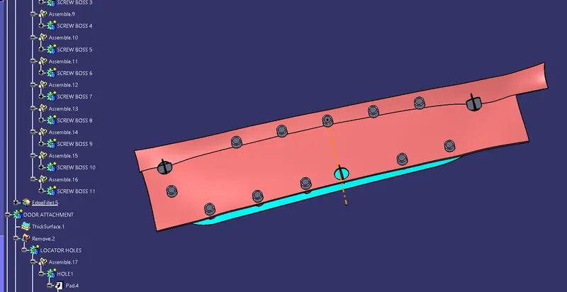
This is the final part which created with attachment engineering features like 4 way locators, 2 way locators and heatstakes.
DRAFT ANALYSIS:
Finally performing draft analysis for both Door applique part and Engineering features along with tooling axis.
DOOR APPLIQUE COMPONENT WITH ENGINEERING FEATURES.
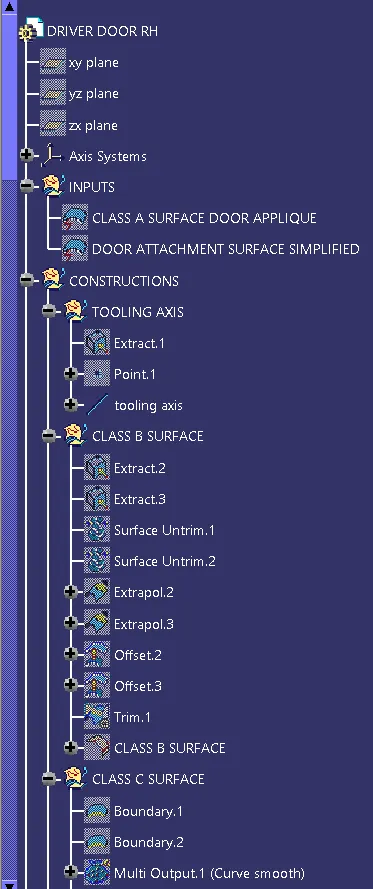
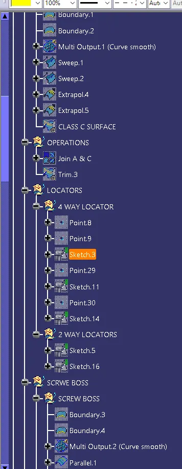
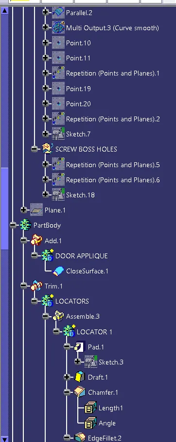
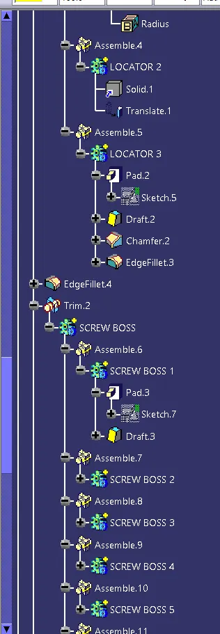
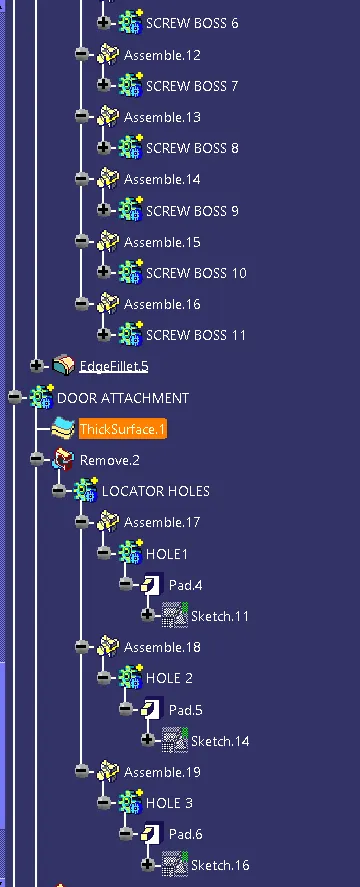
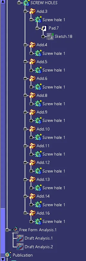
TREE STRUCTURES.
CONCLUSION:
Thus, the Door Applique is developed by using given Class A surface.2 and 4 Way locators have been designed in order to fix the position of the applique with the mating door panel and also designed the heat stakes which used to fix the component with the mating panel by melting.