Week -2
1.
AIM:To creat Simulink model of Doorbell using solenoid block.
SIMULINK AND SIMSCAP BLOCKS USED:
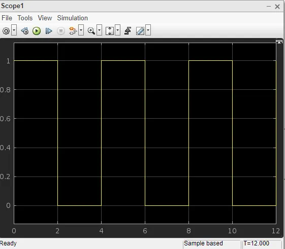
Pulse Generator:It is used to creat time delay of 2sec in solenoid.
Scope:To display the inputs in graphical form.
Simulink-ps converter: Simulink signals can't be accepted in simscap blocks so it converts into physical signal.
PS-simulink converter:The PS-Simulink Converter block converts a physical signal into a Simulink output signal. Use this block to connect outputs of a Simscape physical network to Simulink scopes or other Simulink blocks.
Battery: It gives power supply to doorbell.
Switch: It is used to ON and OFF the power supply to given circuit.
Electrical Reference: The Electrical Reference block represents an electrical ground. Electrical conserving ports of all the blocks that are directly connected to ground must be connected to an Electrical Reference block. A model with electrical elements must contain at least one Electrical Reference block.
Solenoid: The Solenoid block represents the electrical characteristics and generated force for the solenoid in the following figure:
The return spring is optional. To remove the effects of this spring from the model, set the Spring constant parameter to 0.
To show the direction in which the solenoid acts, the block icon changes dynamically based on value of the Motion direction under excitation parameter.
Ideal Translational Motion Sensor block: Motion sensor in mechanical translational systems,The Ideal Translational Motion Sensor block represents a device that converts an across variable measured between two mechanical translational nodes into a control signal proportional to velocity or position.
Mechanical Translational Reference block:The Mechanical Translational Reference block represents a reference point, or frame, for all mechanical translational ports. All translational ports that are rigidly clamped to the frame (ground) must be connected to a Mechanical Translational Reference block.
Solver Configuration:Each physical network represented by a connected Simscape™ block diagram requires solver settings information for simulation. The Solver Configuration block specifies the solver parameters that your model needs before you can begin simulation.Each topologically distinct Simscape block diagram requires exactly one Solver Configuration block to be connected to it.
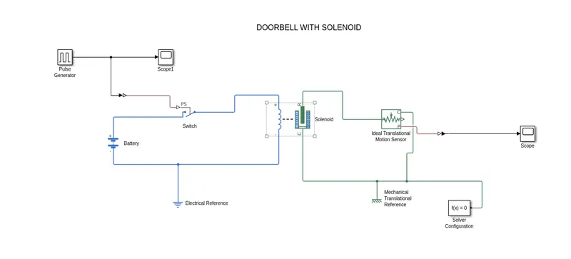
Block diagram:
Pulse generator graphical representation for 2sec runtime and 2sec rest.
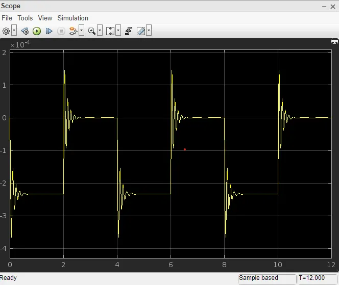
RESULT: Graphical representation of doorbell with solenoid for 2sec runtime and 2sec rest.
2.
AIM: To Use a thermistor to sense the temperature of a heater & turn on or turn off the fan.
SIMULINK AND SIMSCAP BLOCKS USED:
Scope:To display the inputs in graphical form.
Simulink-ps convetrer: Simulink signals can't be accepted in simscap blocks so it converts into physical signal.
Battery: It gives power supply to circuit.
Switch: It is used to ON and OFF the power supply to given circuit.
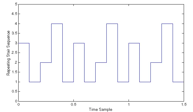
Repeating sequence stair:
The Repeating Sequence Stair block outputs and repeats a stair sequence that you specify with the Vector of output values parameter. For example, you can specify the vector as [3 1 2 4 1]'. A value in Vector of output values is output at each time interval, and then the sequence repeats.
PS-simulink converter:The PS-Simulink Converter block converts a physical signal into a Simulink output signal. Use this block to connect outputs of a Simscape physical network to Simulink scopes or other Simulink blocks.
Controlled Temperature Source:The Controlled Temperature Source block represents an ideal source of thermal energy that is powerful enough to maintain specified temperature difference across the source regardless of the heat flow consumed by the system.
Thermal Reference:The Thermal Reference block represents a thermal reference point, that is, a point with an absolute zero temperature, with respect to which all the temperatures in the system are determined.
Thermister: Negative temperature coefficient thermistor using B-parameter equation.
Voltage sensor:The Voltage Sensor block represents an ideal voltage sensor, that is, a device that converts voltage measured between two points of an electrical circuit into a physical signal proportional to the voltage.
Resistor: It resists the power supply and allows minimum power to flow through it.
Constant: It allows to give input values.
Display: It displays the results coming out from the voltage sensor.
Electrical reference:The Electrical Reference block represents an electrical ground. Electrical conserving ports of all the blocks that are directly connected to ground must be connected to an Electrical Reference block. A model with electrical elements must contain at least one Electrical Reference block.
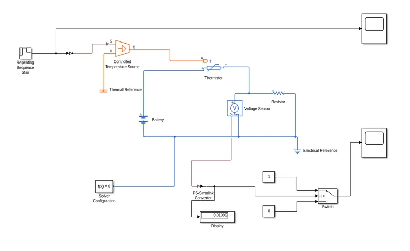
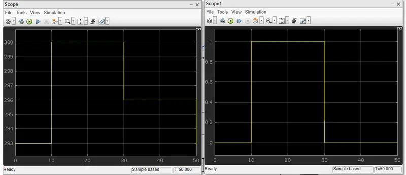
Graphical representation of repeating sequence stair and final graph for temperature source: 20 °C from 0 to 10 seconds, 27 °C from 10 to 30 seconds, 23 °C from 30 to 50 seconds,Fan conditions: ON if the temperature above 25 °C, OFF otherwise