Week 9 - Project 1 - Door Applique Design with Engineering Features
Door Applique Design with Engineering Features
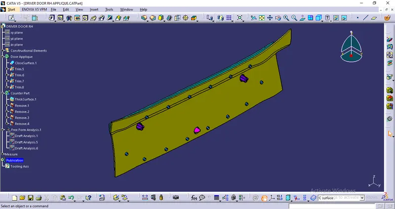
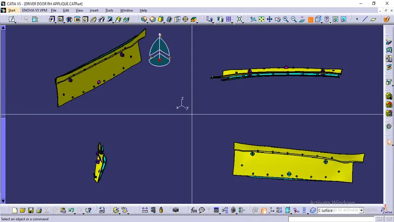
Create the Door Applique Plastic component through the given Class-A surface. Perform the Draft analysis on the model. Create the Heat Stakes and the locators considering the design rules.
Create the door applique plastic component with locators and heat stakes using CATIA v5
1. Create Door Applique
Create class A surface for door applique from provided scanned skin file -
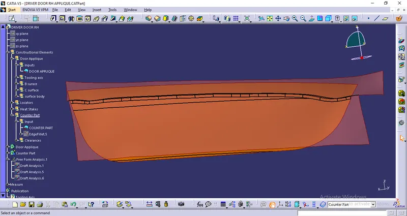
Create tooling axis-
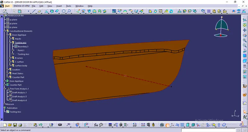
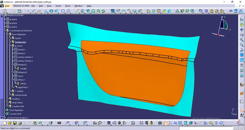
Create B surface-
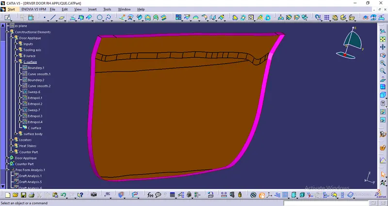
Create Class C surface-
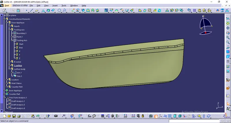
Using Class A, B and C surface create create Surface body-
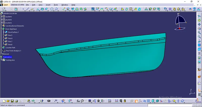
Using fill surface create solid body from surface body-
2. Create Locators on Door Applique body
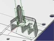
We have two objectives when mounting a part in a fixture.
- Accurately position the part at the desired coordinates.
- Restrict all six degrees of freedom so that the part cannot move.
A widely used method of accomplishing these two objectives uses the 3-2-1 principle, so-called because it entails three steps that employ three, then two, then one fixed points of known location. Since that adds up to six fixed points, it’s also known as the six point method.
In the three steps of the 3-2-1 method, three mutually perpendicular planes, called datum planes, are introduced, one at each step. These three planes define the workpiece position, and together with opposing clamping forces fully constrain the part. For this locators comes into play.
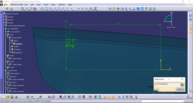
Create sketch for 4 way locators
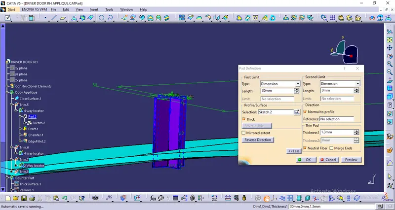
Extrude the sketch and proved draft of minimum 0.5 degree-
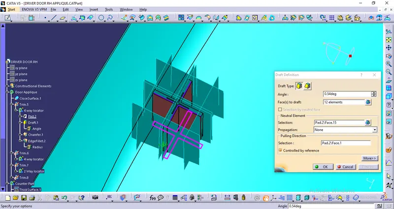
Provide chamfer on edges and fillet with maximum 0.25 mm radius-
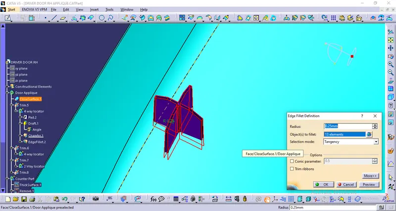
After translating to as many positions as required union trim locator body with main body-
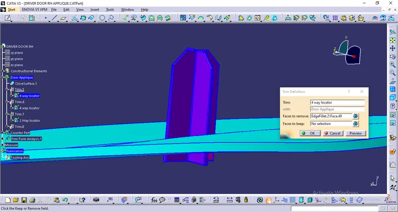
Create sketch for 2 way locator-
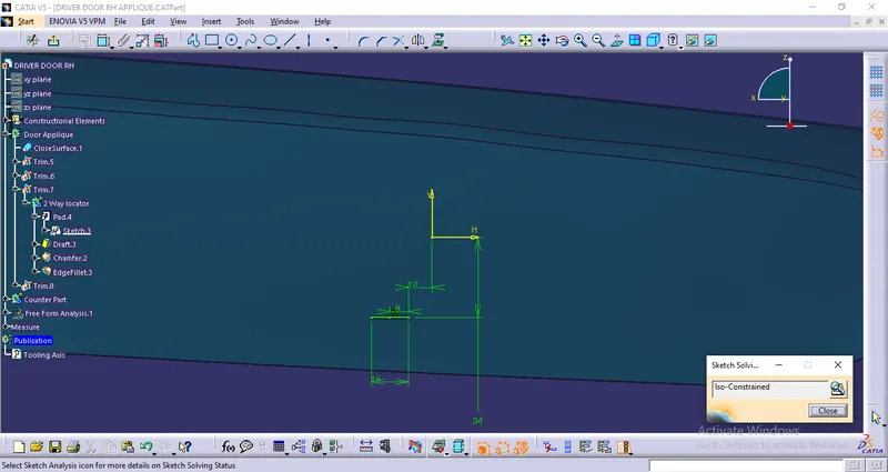
Extrude the sketch and proved draft of minimum 0.5 degree-
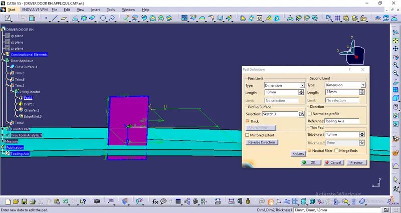
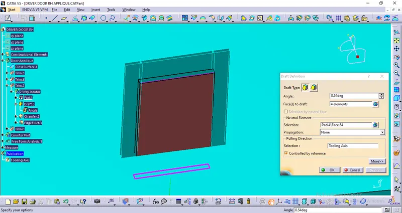
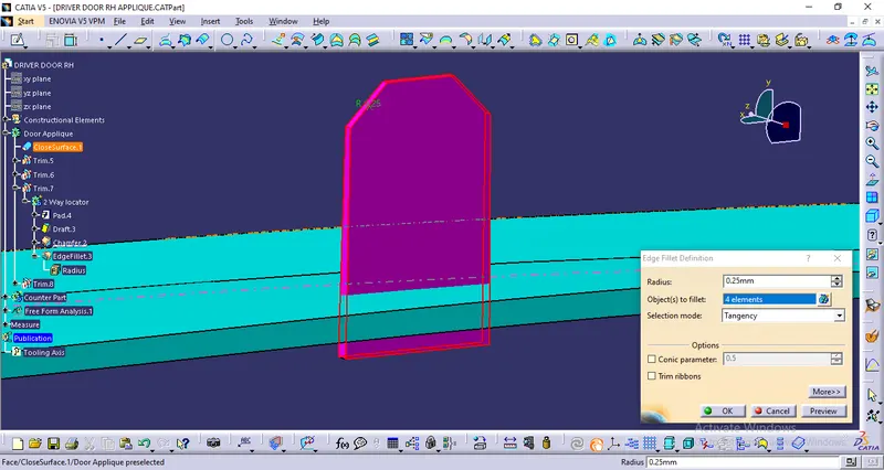
Provide chamfer on edges and fillet with maximum 0.25 mm radius-
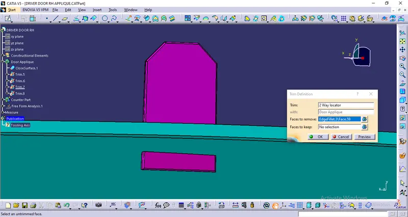
After translating to as many positions as required union trim locator body with main body-
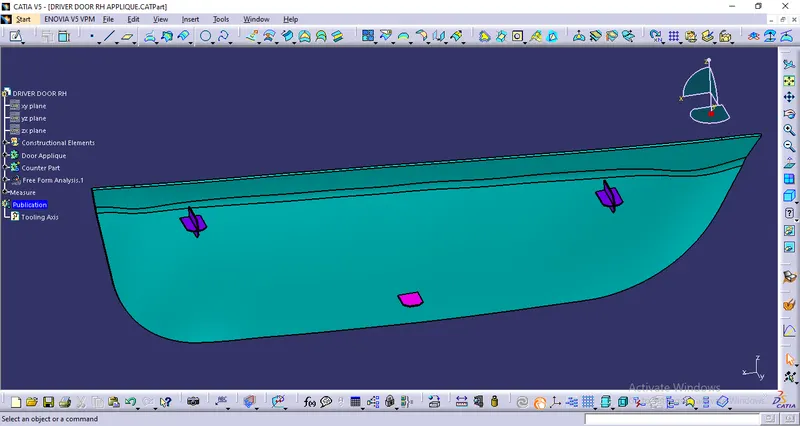
Door Applique with both types of locators-
3. Create Heat stakes to join Door Applique body with counter part
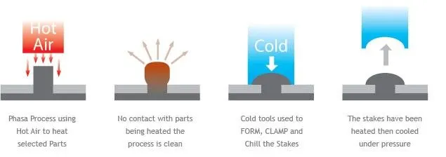
Heat staking also known as thermoplastic staking is the process of joining two dissimilar materials together. In heat staking we use local heating and cooling to raise the temperature of plastic components and allow plastic reforming to be carried out. This reforming can be used in a wide variety of applications.
Applications range from staking plastic boss’s for assembly of car door panels to joining PCB’s to plastic housings. Benefits of this technique include; no vibration damage, no particulates, the ability to stake metalized coated applications and the capability to stake in difficult to access or restricted areas.
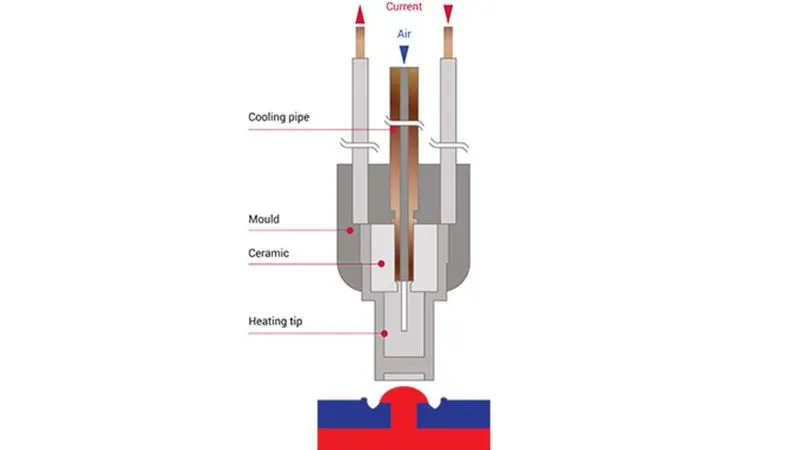
Types -
Standard Flared Stake
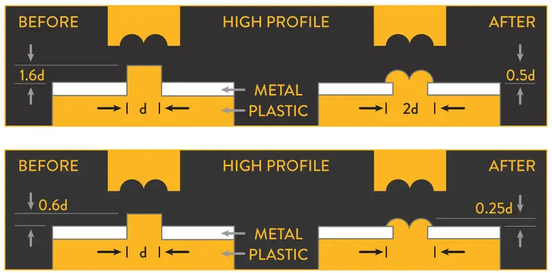
Shperical stake
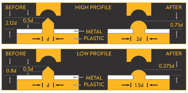
Knurled stake
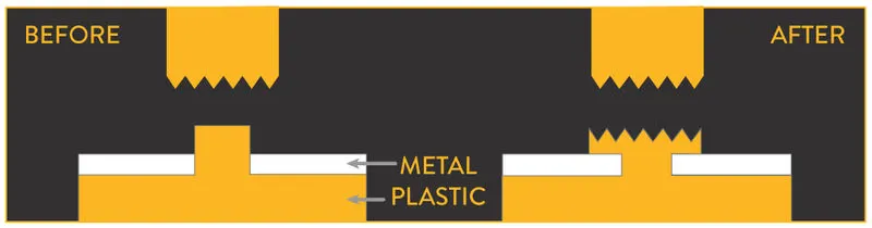
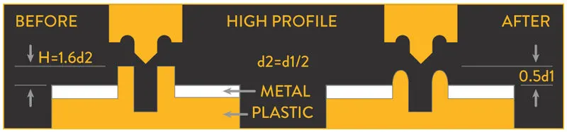
Hollow Stake
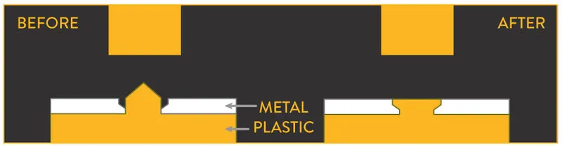
Flush Stake
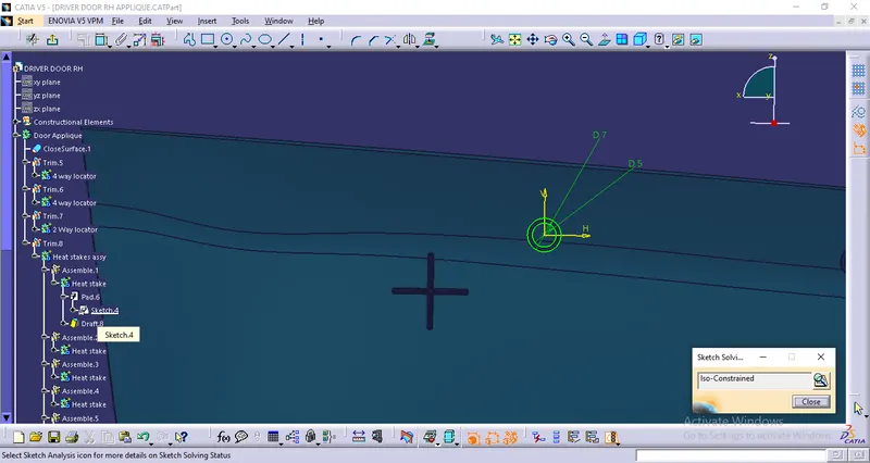
Create sketch for the heat stake on door applique-
Extrude the sketch and proved draft of minimum 0.5 degree-
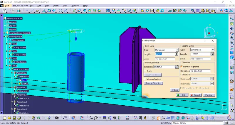
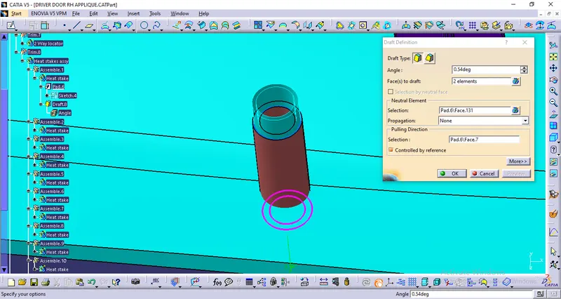
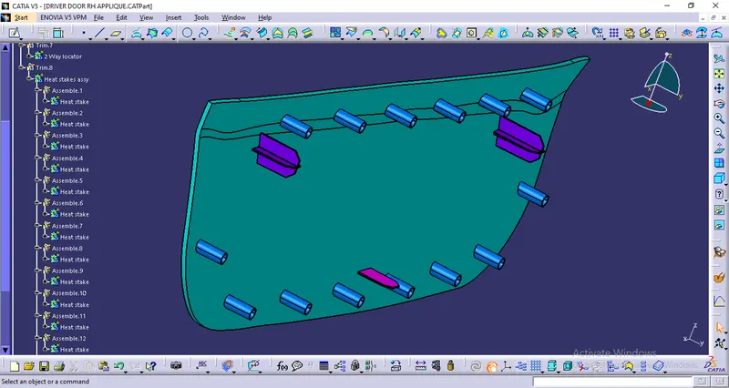
Translate heat stakes to as many positions as required-
Draft analysis -
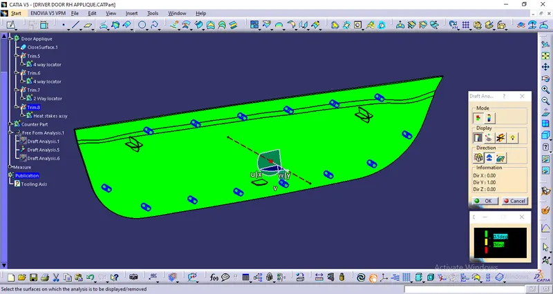
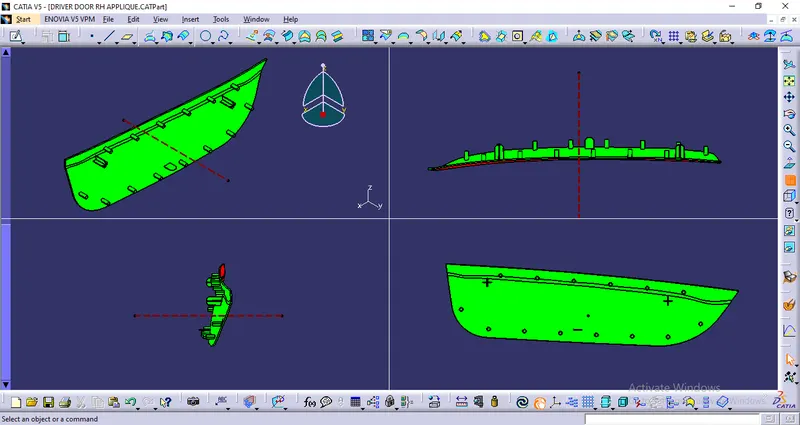
4. Create clearances for locators and heat stakes on counter part
Create the Class A surface for Counter part
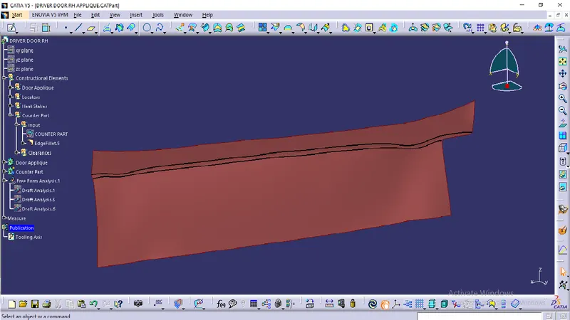
Thicken the surface to get the counter part body-
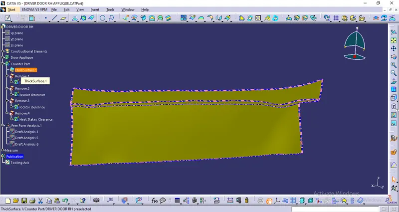
Using the sketch of locators and heat stakes create clearance holes with 0.1mm on counter part-
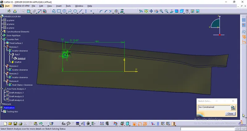
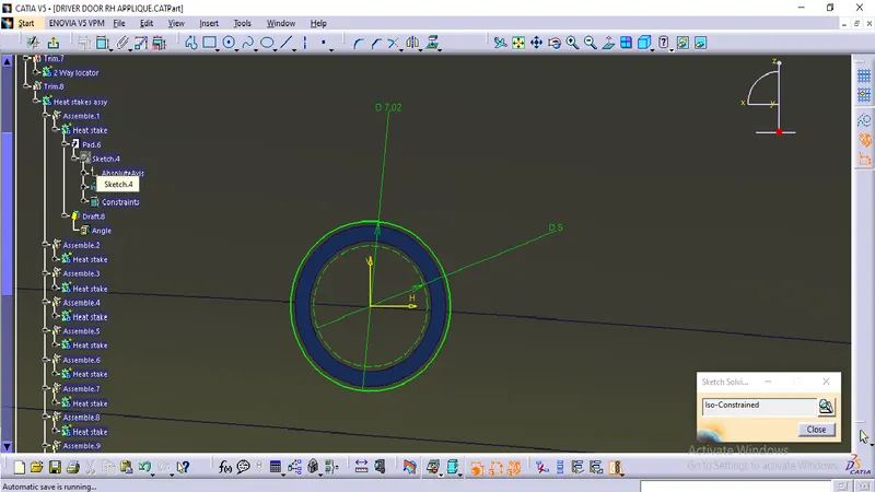
Extrude the sketch and provide required draft of minimum 0.5mm-
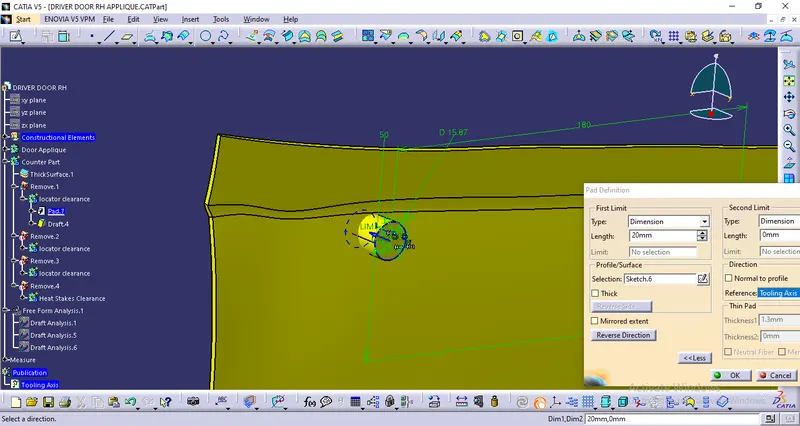
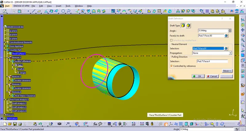
Using boolean operation remove the extruded body from main part body to create hole for locators and heat stakes with clearance 0.1mm -
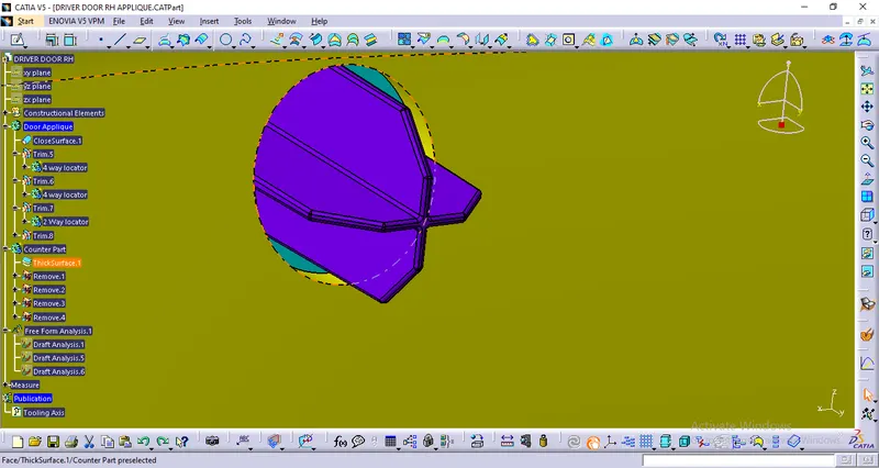
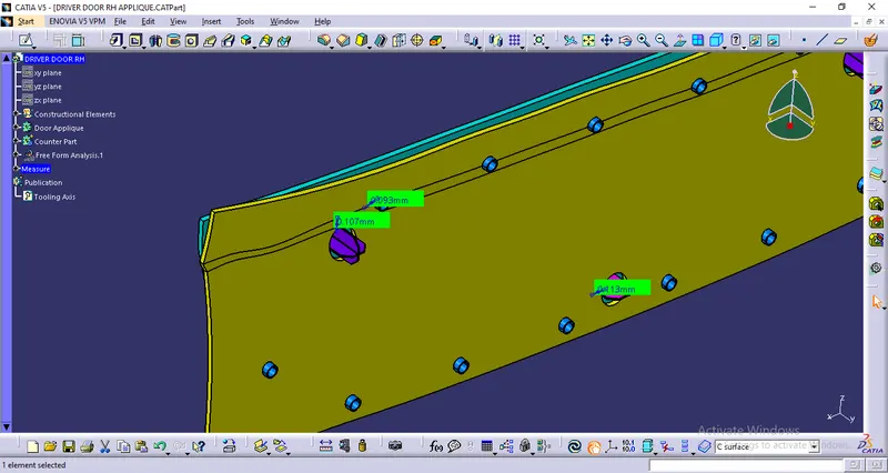
Draft Analysis-
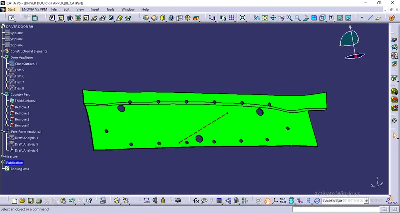
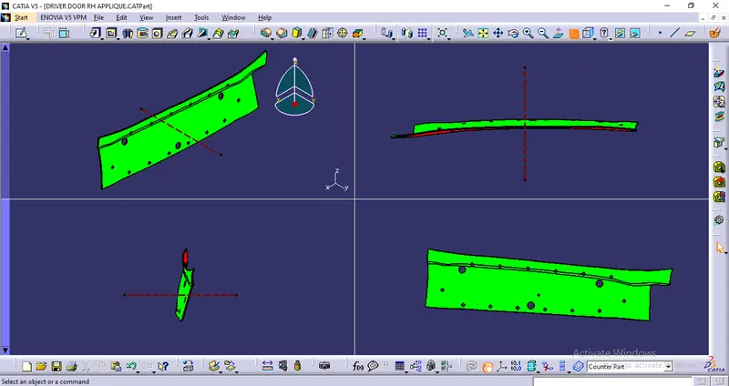
Final Model-