Hood design-Week 2
HOOD DESIGN
Design of car hood outer panel, inner panel and necessary reinforcements following EURO-NCAP regulations.
DEFINITION-

Car Hood or Bonnet is a engine covering part which provides stlying for outer car body and also provides the strength to the front end of car. It is hinged and can be opened to allow access in the engine compartment.It has to be opened first from driver compartment by a butten and then manually from front by sliding a lever attached to the latch.
Other than basic functionality, hood can also provide safety to the passengers by distributing the impact force during an accident to sideways towards the hinge so that passenger comparment has to bear minimum impact. In this report this will be further discussed.
COMPONENTS-
A hood consists of these following componets.
1. Outer panel
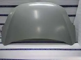
This is the visible part of the hood it needs to look aesthetic to complement the outer body of a car. Thickness 0.65-0.75 mm
2. Inner panel
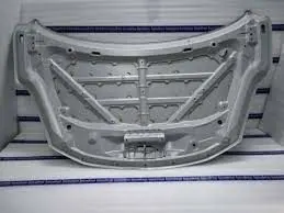
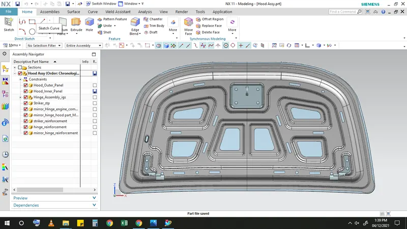
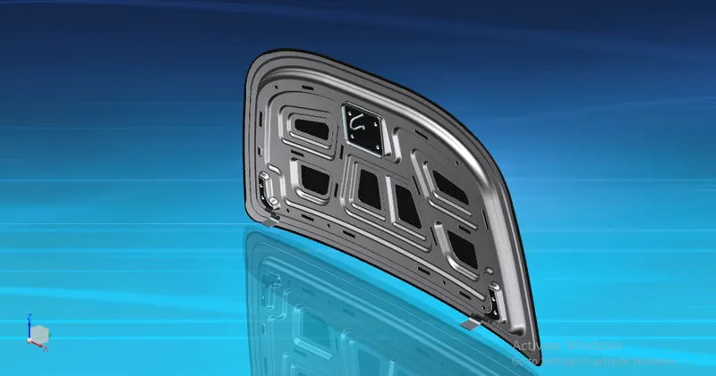
This is most complicated yet most important part of a hood. Inner panel provides the required strength to the outer panel without compomising the look of the outer panel a whole lot of R&D goes into developing this part to make it effecient and cost effective.Thickness 0.65-0.75 mm
3. Striker
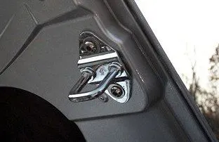
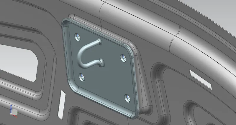
This is the U-shaped part placed on inner panel which goes into latch to lock the hood while closing.
4. Hinge
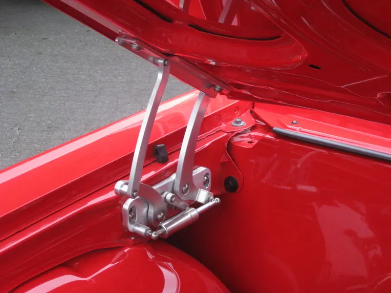
There are generally two hinges on both side of inner panel so that hood can be open and close.
5.Reinforcements
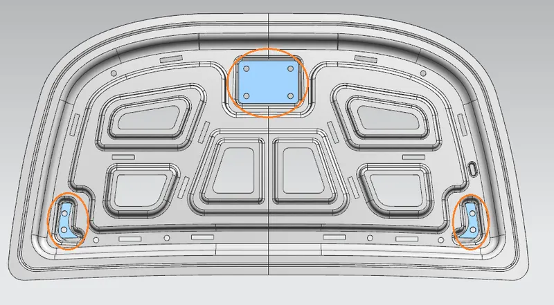
At the position of striker and hinges the innder panel need to have more strength. So there come the role of Reinforcements, to strengthen the inner panel.
6. Support rod/gas stay
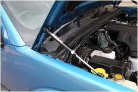
support rod or gas stay both enables the hood to keep in open state during the maintenance work. This is very cruicial part because its size and positioning decides the opening angle of the hood.
CONSIDERATIONS-
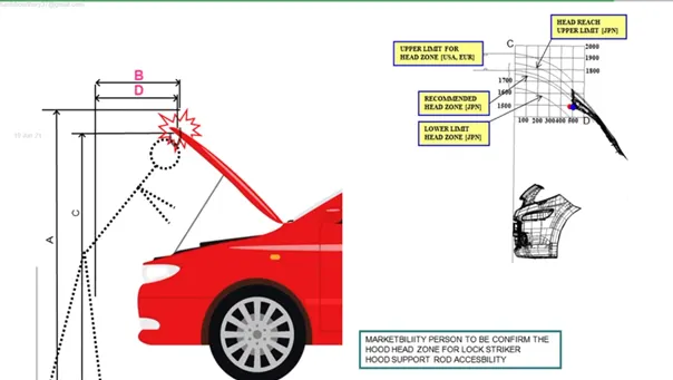
1. Head clearance- This changes from country to country depending upon average heght of peope is that country.
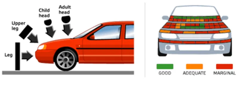
2. Padestrian safety (Euro-NCAP regulations)  - The European New Car Assessment Programme (Euro NCAP) is a European voluntary car safety performance assessment programme. This study concludes the head impact zone for child and adult which will take place during a crash, so that impact can be minimized by increasing the green zone in hood area by increasing space between engine commodity and inner panel.
DESIGN OF HOOD COMPONENTS USING NX CAD-
1. Outer panel and inner panel
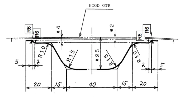
Given - Master section
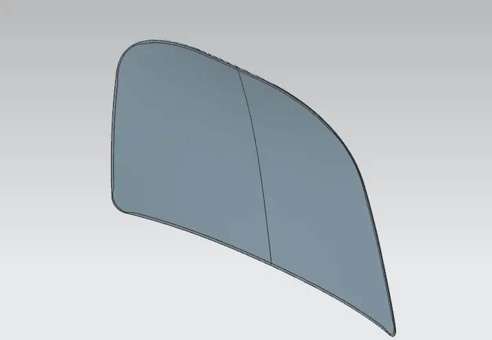
1.Construct the surface of the hood outer panel with the provided skin.
2.Using the given master section prepare the outer surface of inner panel.
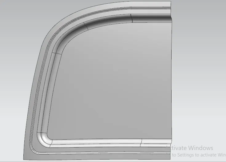
Emboss-
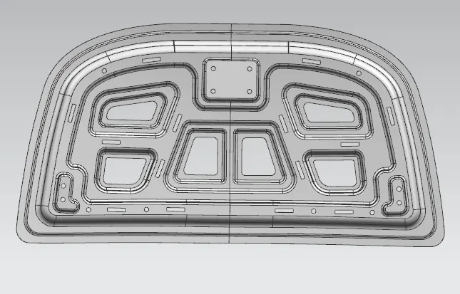
Emboss need to be design by taking manufacturing process deep drawing into the account. So it is necessary to provide required draft.
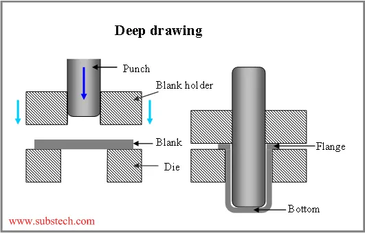
Further this design will be analyzed by CAE team and give their feed back.
3.Provide embosses on the inner panel by providig space for hinge and striker placement.
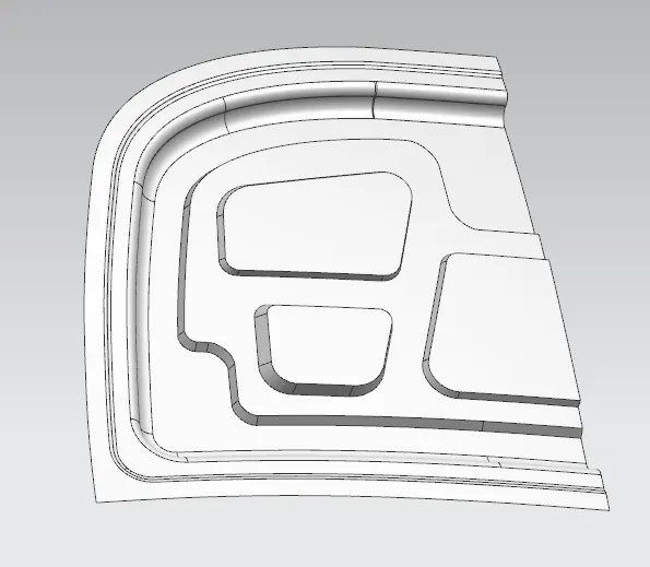
4.Embossing process may be take place in several stages.
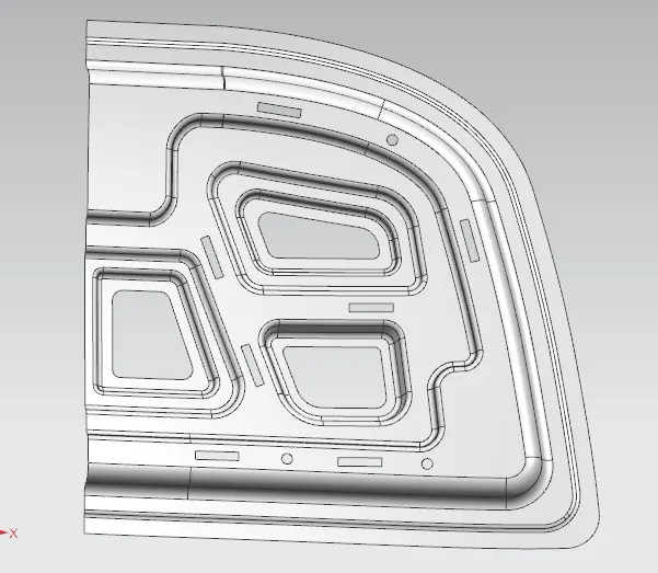
5. Provide a embosses for hinge and striker placement with the flat surfaces.
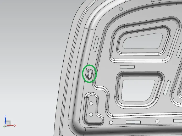
6. Provide a seperate emboss for the Support rod placement during opening the hood.
2. Hemming outer panel over inner panel.
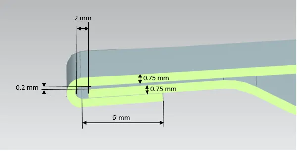
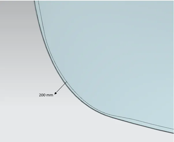
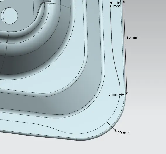
Given- Hemming data
Theory-
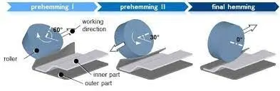
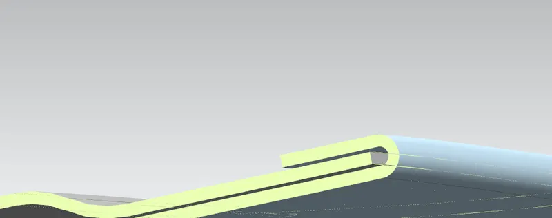
Hemming is a sheet metal forming process in which sheets are joined by bending it to 180°. Automotive body panels and automotive parts such as deck-lids, trunk-lids, doors, hoods and tailgates are formed by hemming process. In this process, usually a sheet is bent with the help of inner sheet in three different stages.
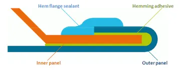
To keep the aesthetic looks intact while joining riviting or welding are not preferable. Here comes the role of Mastic, there is adhesive placed between two sheets to join them together. After this hemming process finla stage is to apply sealant.
To join properly and avoid NVH, outer panel join wiht inner panel by applying many adhesive at various portion called mastic points.
1. Offsetting the outer panel to make wrap around surface over inner panel considering the parameters given in the hemming data.
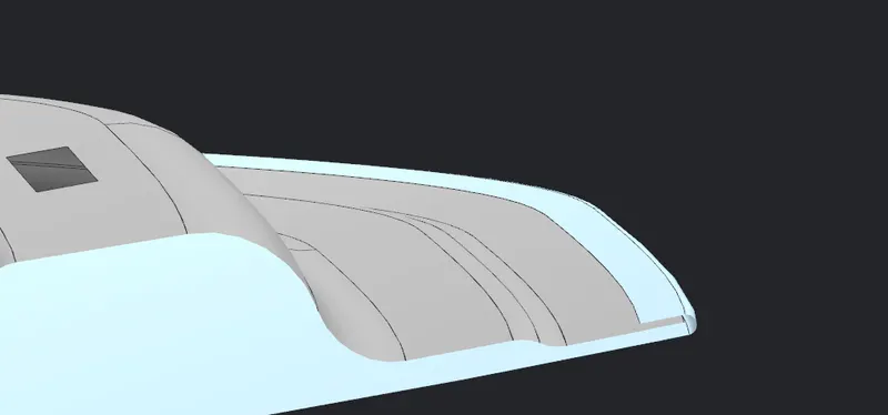
2. Provide relives at the cornors for effective hemming, as per the data.
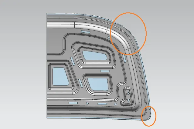
3. After mirroring thicken the surfaces with 0.75 mm.
3. Hinge and Striker placement
1. place the hinge on the flat embossed surface and mirror it.
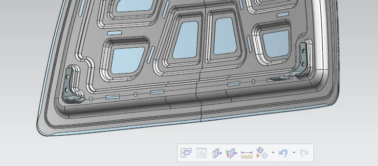
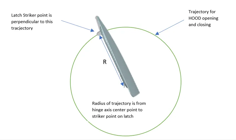
2. Make latch trijectory from middle of hinge axis to define the position of the striker in assembly interface.
(As it is obvious that this is a top down Approch so the inner panel finalization and Stirker placement will take place simantainously.)
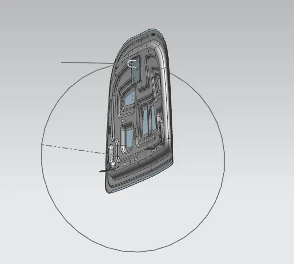
Theory-
For every moving part like doors, tail gate and hood this study is applicable. In this we check wheather the position of the hinge axis is right or not by checking the perpendicularity of the trajectory and striker position.
3. By using wave linker geometry prepare emboss for striker placement.
4. Reinforcements for hinges and striker
1. Using Wave linker geometry create surface for Reinforcements and move Them beind the inner panel.
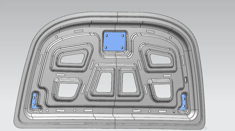
2. Apply necessary assembly constraints and thicken them.
Final Assmebly-