Week 9 - Project 1 - Door Applique Design with Engineering Features
Aim :- Create the Base Bracket Plastic component through the given Class-A surface. To begin with, the tooling axis for the given Class-A Surface is created meeting the requirements of the draft angle and at the end perform the Draft analysis on the model.
Create the Heat Stakes and the locators considering the design rules.
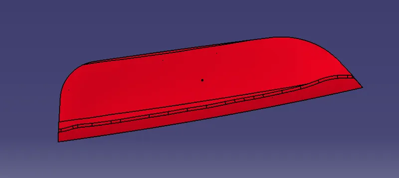
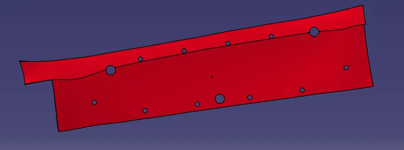
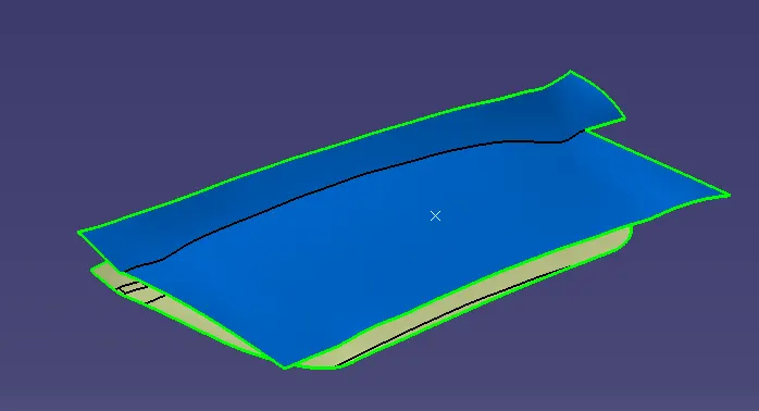
Given surfaces :- (Door Applique and attachment surface).
Procedure :-
- To create loctators and heat stakes on the given surface of a side door. the main purpose of these are they act as fixtures bwtewwn the two components. locators are used to lock the degrees of freedom and while the heat stakes are used to attach them firmly.
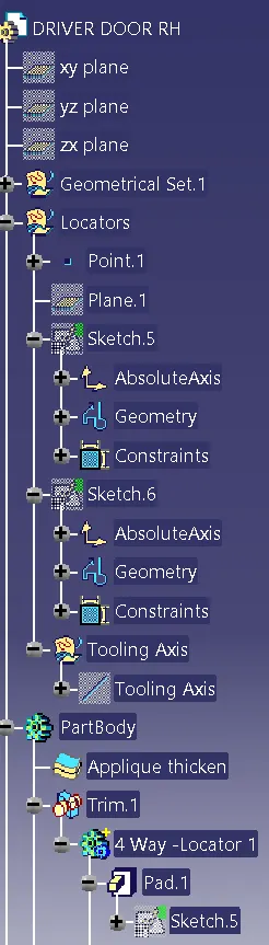
- Insert a geometrical set naming locators.
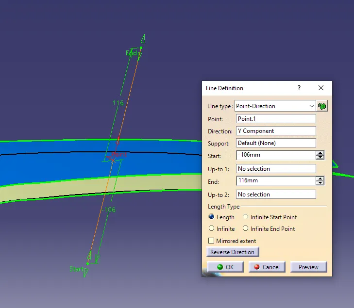
- Create a point on the upper surface and crearte a plane parallel through that point in the direction parallel with the surface. insert another geometrical set and name it as Tooling axis. create a line throught the created point in Y-direction. and extend it enough.
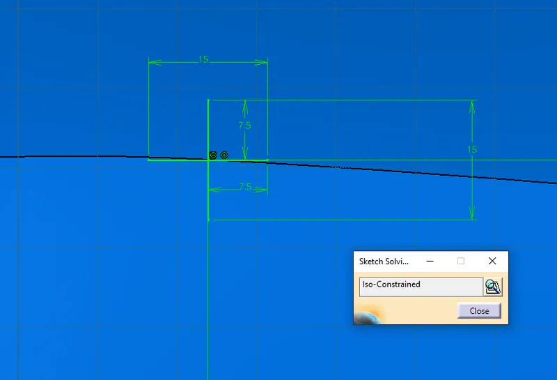
- Create a positioned sketch through the point created and the reference as the plane parallel through the point. draw the 4 way locator sketch with required dimensions. make sure the sketch is place at approperiate location and is iso-constrained.
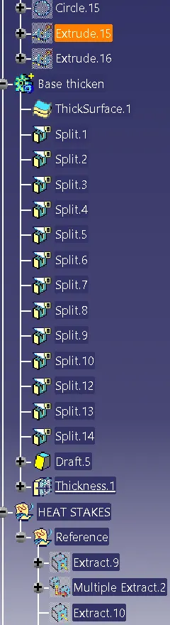
- Now Goto part body and thicken the two surfaces with 2.5mm as thickness. thicken both the surfaces in approperiate directions.
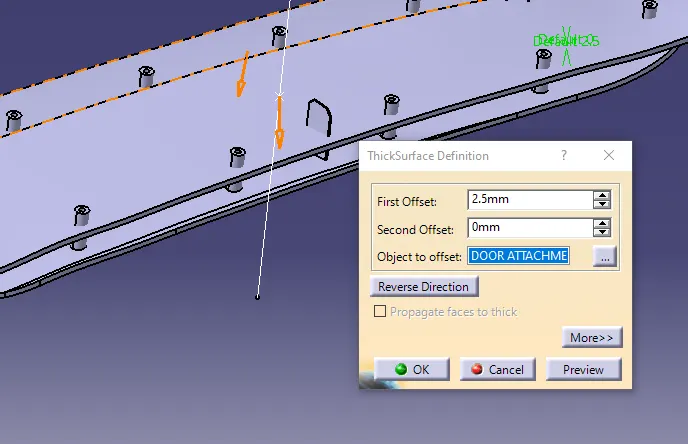
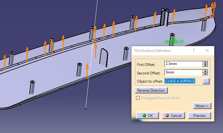
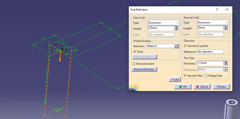
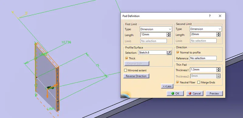
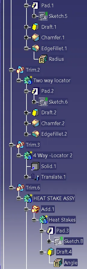
- Pad the created sketch with thickness 1.3 mm neutral fibre and extend in one limit. insert a separate part body and rename it as 4 way locator 1 and define it.
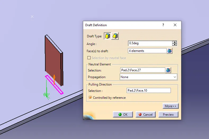
- Draft the faces of the locator with 0.5 degrees and neutral element as the base of the locator , choose the tooling axis as pulling direction.
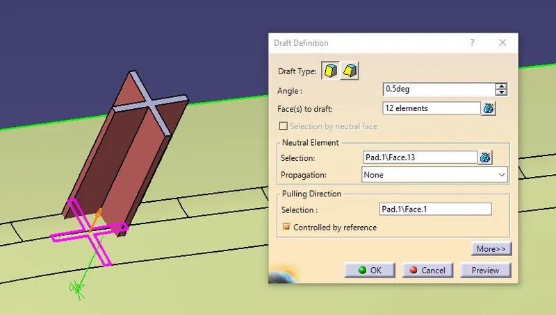
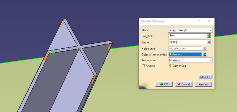
- Add chamfers to the edges on top with 45 degrees radius 2mm length.
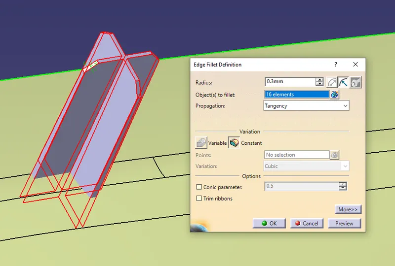
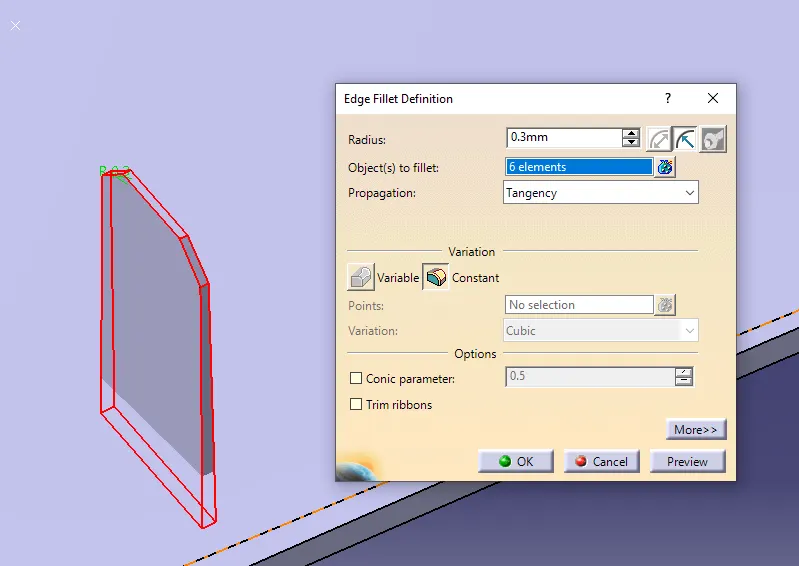
- Similarly add edge fillets to all the faces with 0.3mm as radius.
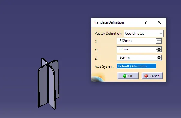
- Now to create another similar 4-way loactor in different location,. copy paste the part body and paste specials.. in the main folder use translate command to replicate the same body in different loaction use co-ordinate system to translate. make sure the heights of the locators should be similar from the attachment surface.
- Now to create a two way locator define the locators geometrical set and create positioned sketch with the refrence point and plane as direction. draw the two way locator sketch and constrain it with the axis system. exit the sketch and insert a part body rename it as two way locator.
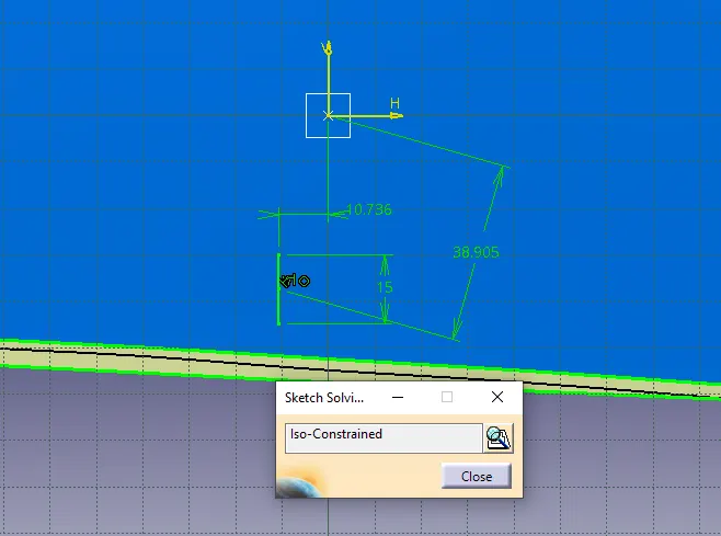
- Similarly Pad the sketch to the similar height that of the 4 way locator and with 1.3mm thickness and neutral fibre option.
- Draft the side faces of the locator with 0.5 degrees and select the base of the surface as neutra element and tooling axis as pulling direction.
- Add edge fillets and chamfer similarly as that of the 4 way locators.
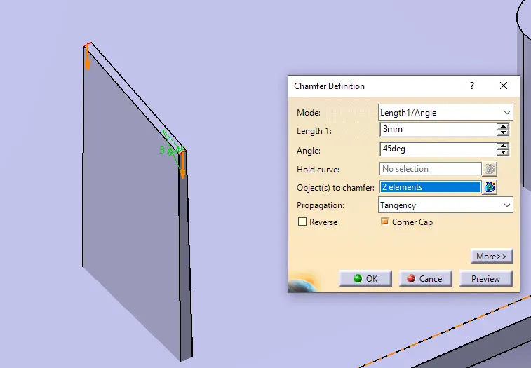
- Now using Boolean operation- ADD the 3 part bodies two 4 way locators and one 2 way locator to the main part body .
- Heat stakes are created in at the boundries of the surface. make sure that the heat stakes are a min of 50mm apart from eachother. insert a a geometrical set and name it as heat stakes and define it.
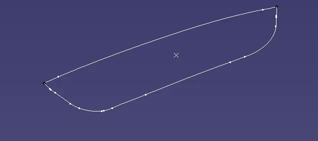
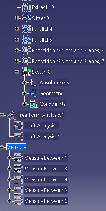
- Now unhide the upper surface and using multiple extract option extract the boundries using tangent propogation.
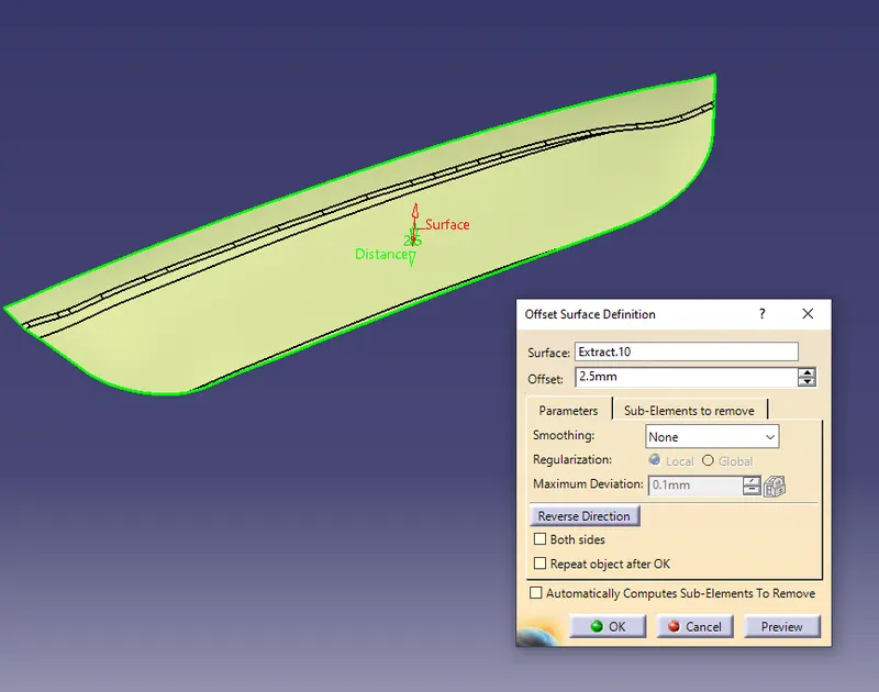
- Extract the surface of the attachment and off-set it to 2.5 mm upwards as the thickness of the component is 2.5mm
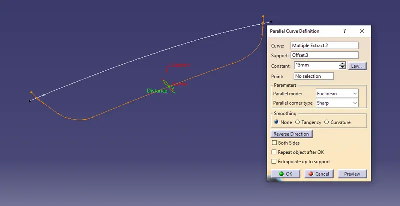
- Since the heat stakes are placed with certain distance away from the boundries. use the parallel curve option and 15mm distance the created boundries and the off-set surface as base.
- Now using the points repetetion option create multiple points on the parallel curve. unhide the soli body and make sure the heat stakes arent interfering the locators.
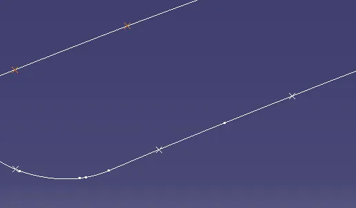
- Now create a positioned sketch through the points created on the parallel curve. let the outer diameter be 7 and the inner diameter as 5.
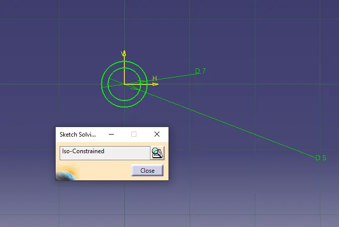
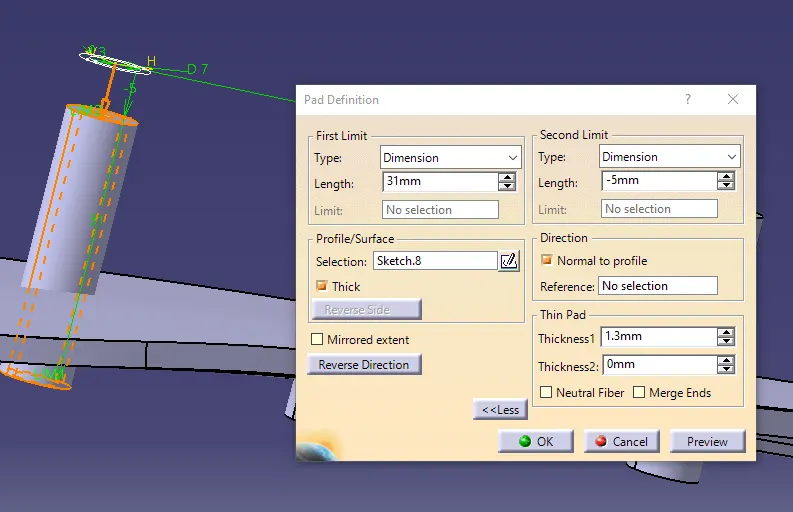
- Exit the sketch and insert a part body and rename it as heat stakes and define it. pad the sketch to 1.3mm thickness and 35mm height /neutal fibre.
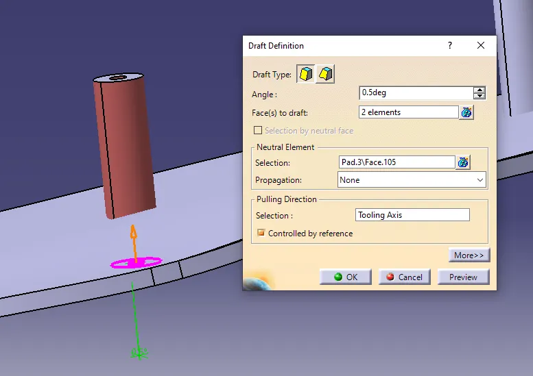
- Draft the faces of the heat stakes with 0.5 degree and neutral surfaces as the base and tooling axis as pulling direction.
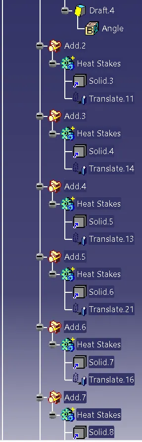
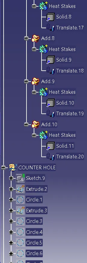
- Now copy- paste special.. the heat stakes part body to the main folder and translate it to the other points on the parallel curve with point to point option. similarly perform the same procedure to transalet it to the other points on the parallel curve.
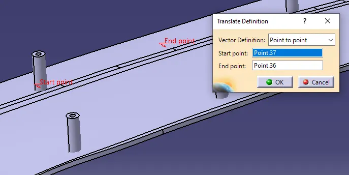
- Now using Boolean operation- ADD the part bodies of heat stakes to the main part body. add edge fillets with 0.3mm radius to all the heat stakes created.
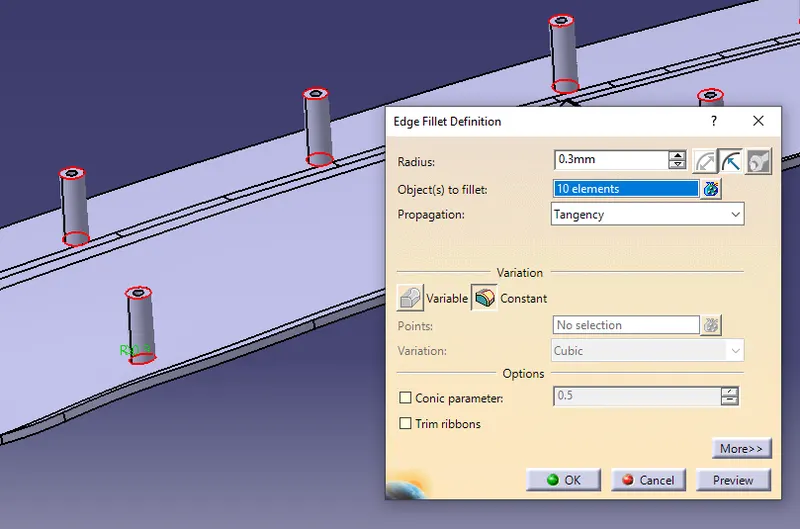
- Hence the heat stakes and locators are created according to the design guidlibnes on the applique surface. now counter holes need to be created on the attachment surface.
- Insert a geometrical set and rename it as Counter holes and define it. we can create in two different ways one by creating a positioned sketch through the reference point from the previous sketch or by goint to part design and creating a a circle through the points on the parallel curve. use point-radius option.
- Make sure the clearance between the surface and the features created is a minimum of 0.5mm. hence increase the diameter of the circle by 0.5mm
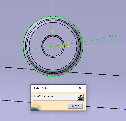
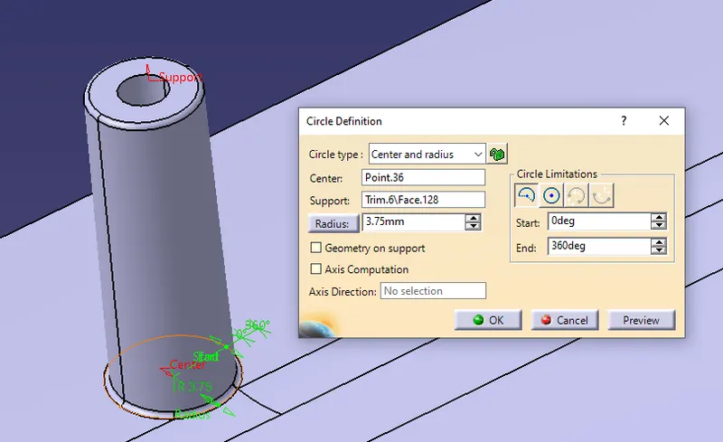
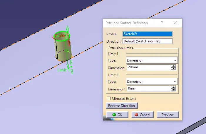
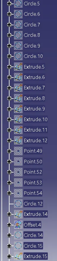
- Now extrude the circle to certain height and define the attachment solid part and through part body design SPLIT the extruded surface with the solid part to get a counter hole
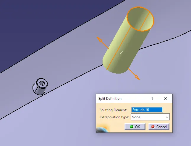
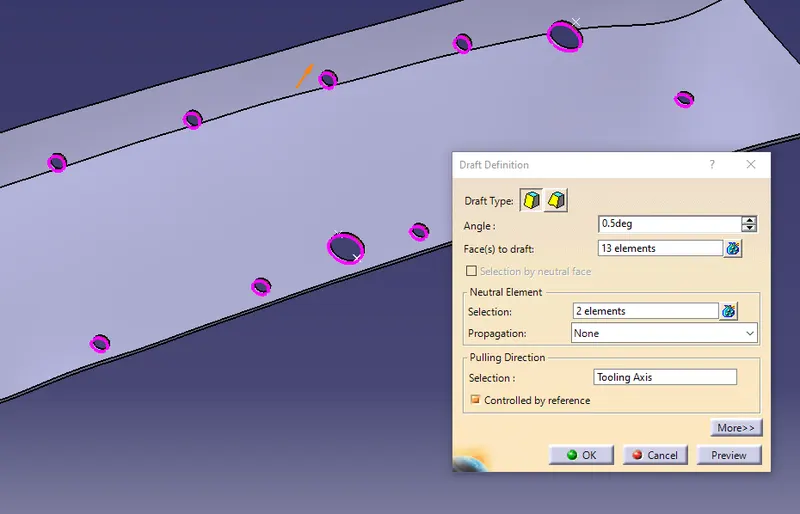
- Now Draft the counter part surface with 0.5 degree with the tooling axis.
- Using the measuring tool check for the clearance between the attachment surface and the locators and heat stakes created .
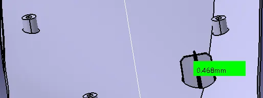
- Hence the aim of creating locators and heat stakes on the applique part and clearing them through the attachment surface following the design rules.
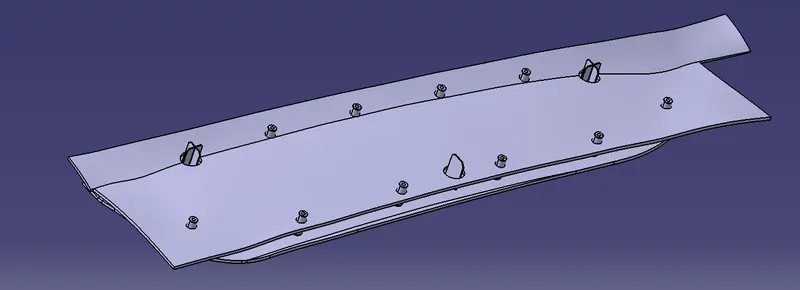
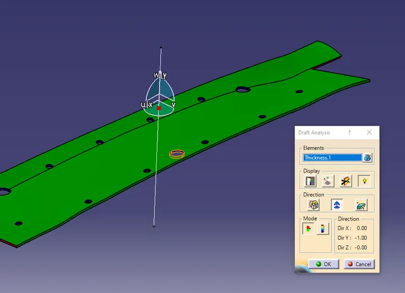
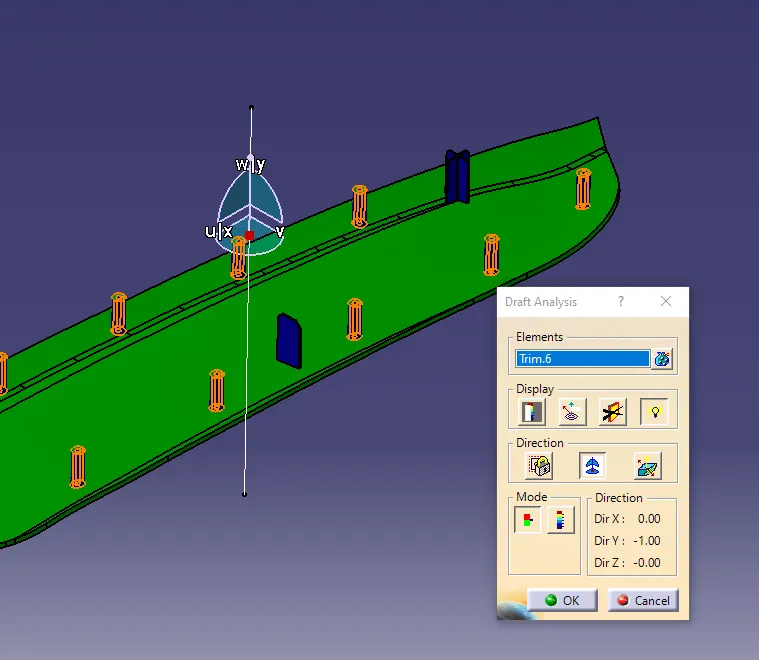
- Now perform the Draft analysis on the components. goto Insert- Analysis - Feature Draft analysis. select the attachment surface and place the compass on the tooling axis. inspect the component visually.
Model tree :-
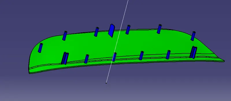
Result :-
Isometric view -
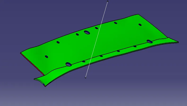
Top view -
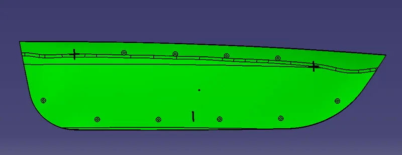
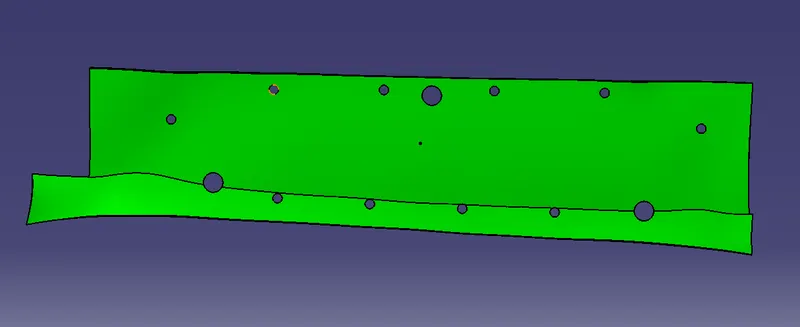
Side View -
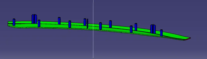
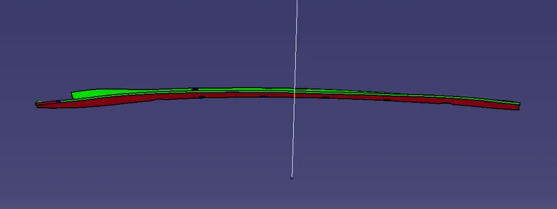
Bottom view-