Week 9 - Project 1 - Door Applique Design with Engineering Features
DOOR APPLIQUE DESIGN WITH ENGINEERING FEATURES
Door applique is one of the main component which is assembled on to the car door. It is fixed in the door as mentioned in the figure below.
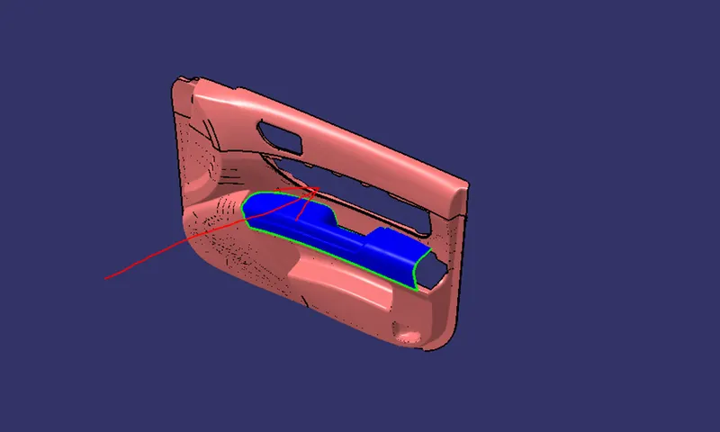
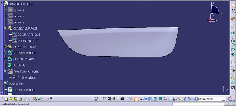
Now our task is to design the full door applique including the engineering features, which will help us to fix the component into the main body. The Class A Surface of the door applique is been provided to us as shown in the figure below.
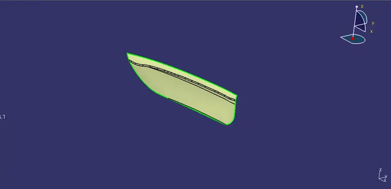
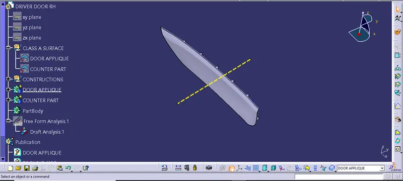
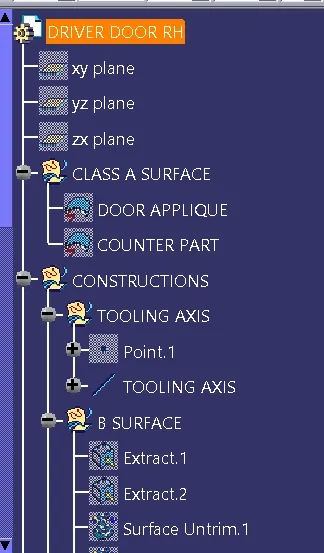
Now our task is to convert the Class A Surface into the solid manufacture-able product. But before that we need to check if the given product can be manufactured or not. So initially the tooling axis drawn which confirms that the product can be manufactured as shown in the figure below.
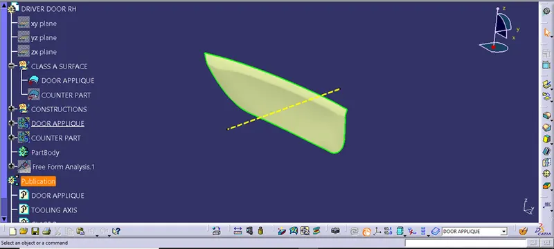
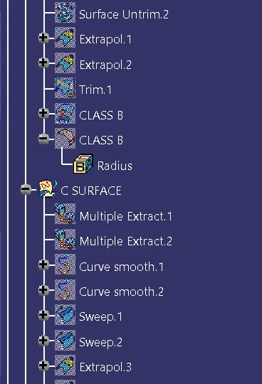
Now we have to initially create the Class B Surface, so the Class A Surface is been extracted, untrimmed and is offset 2.5mm in the inside direction as shown in the figure below.
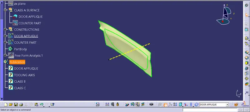
The upper surface is Class A and the lower surface is Class B Surface.
Our next task is to create the Class C Surface. So to create the C Surface initially the boundary is extracted, then the smooth curve option is used in order to make the extracted curve smooth. And then the sweep command is used to create the Class C Surface. The angle of the sweep given is 3degree. Here the direction of the sweep selected is outward direction and finally the edges of the sweep is extrapolated and is trimmed as shown in the figure below.
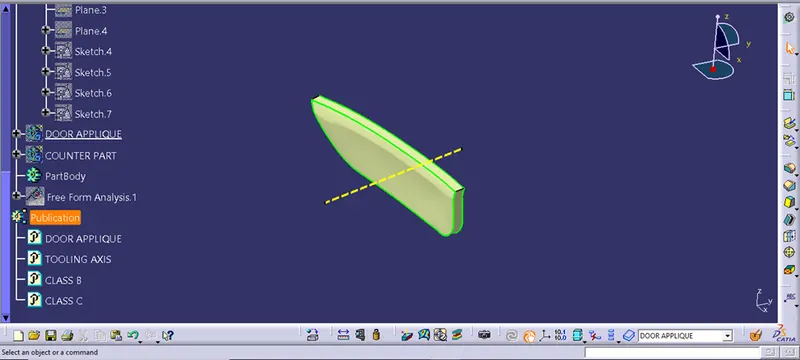
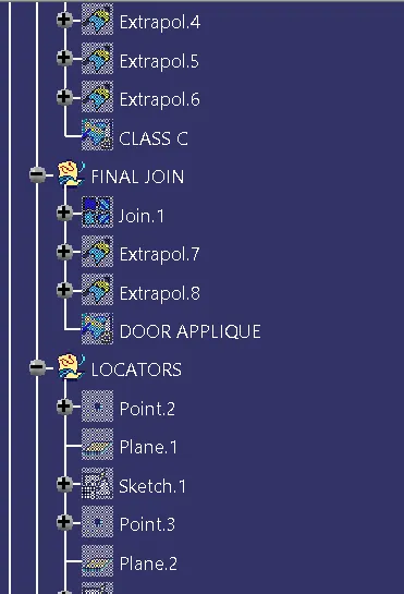
Now initially the Class A and the C surface is join with the tolerance of 0.001mm. Then the Class B Surface is trimmed with the whole body and hence we get the final design of the product as shown in the figure below.
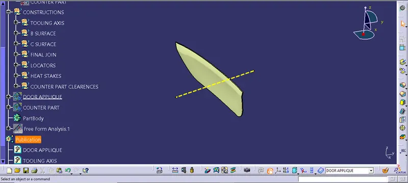
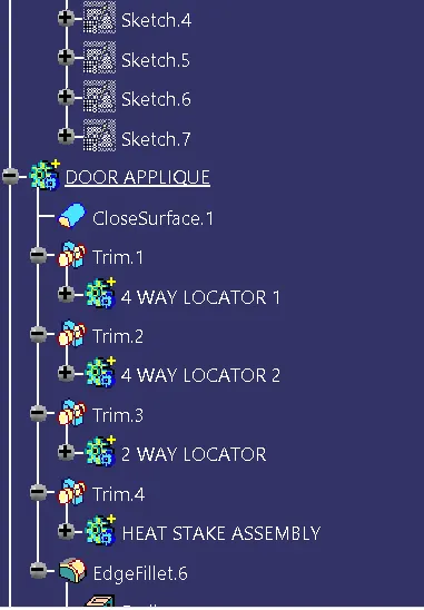
Now the new body is inserted and the closed surface option is used to convert the body into the solid as shown in the figure below.
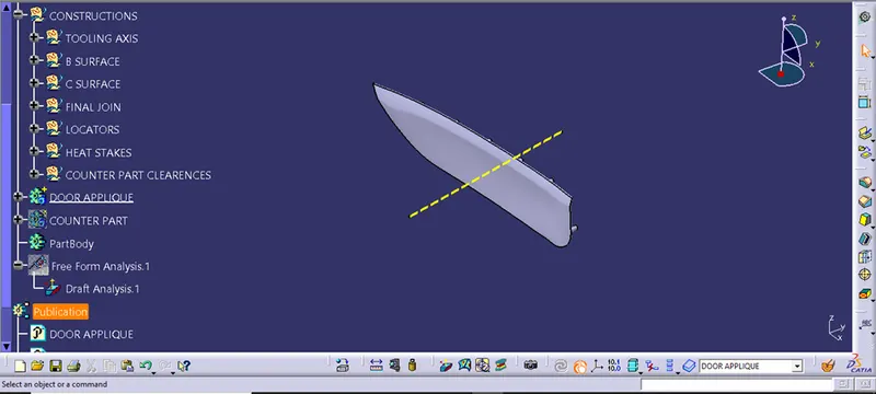
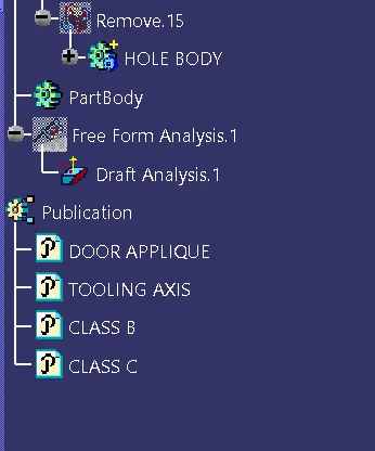
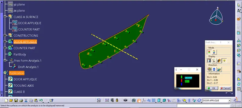
Now the draft analysis is done to check if the tooling direction drawn is correct as shown in the figure below.
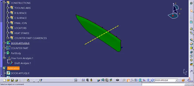
Now our whole door applique is designed, our next task is to design all the engineering features on the B side surface in order to fix the component with the main body.
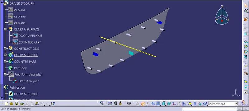
Now the new geometrical set is inserted and it is named locators. A point is drawn on the b side of the component along with the XZ plane, then the sketch of the 4 way locator is drawn and is pad along the downward direction and the draft of 0.5mm is given as shown in the figure below.
The design rules of the locator are as follows :-
Locators are designed on to the component to restrict the degree of freedom of the particular component.
As such there is no rule for the height of the locator, it depends upon the size of the component, although the clearance of the locator should be 0.1mm not more than that.
Here both the lines have dimension of 15mm i.e 7.5mm each side and is at certain distance from the tooling axis.
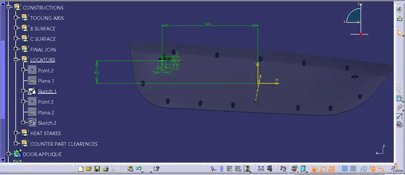
Now the same locater is paste special along with the link and is translated to the right most corner of the component as shown in the figure below.
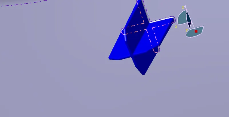
Now the 2 way locater is sketched on the same sketch plane and is pad by inserting the new body in the downward direction as shown in the figure below.
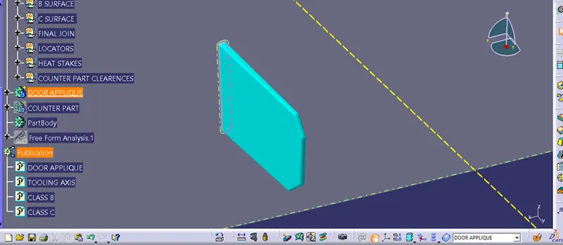
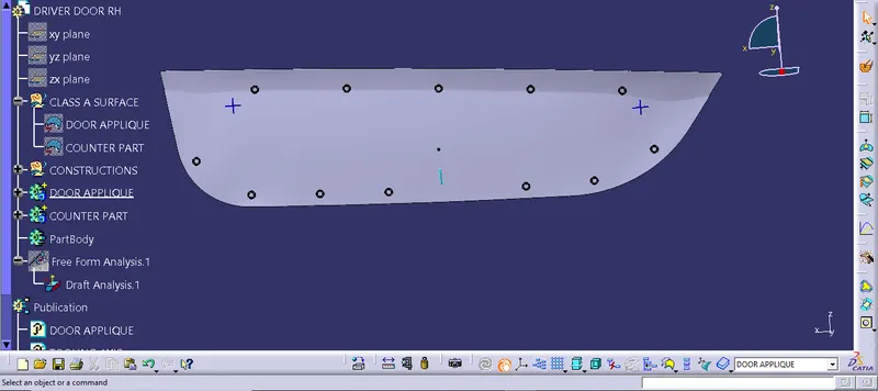
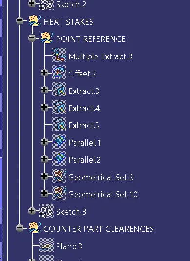
Here comes the main part where we have to mark the reference points and to find the number of heat stakes which we have to design. So initially the Class A Surface is extracted and is offset 2.5mm in the inward direction. Now the boundary is extracted and the parallel curve option is used on both the extracted curves and finally the points and plane repetition command is used and the points are drawn on to the curves with some instances as shown in the figure below.
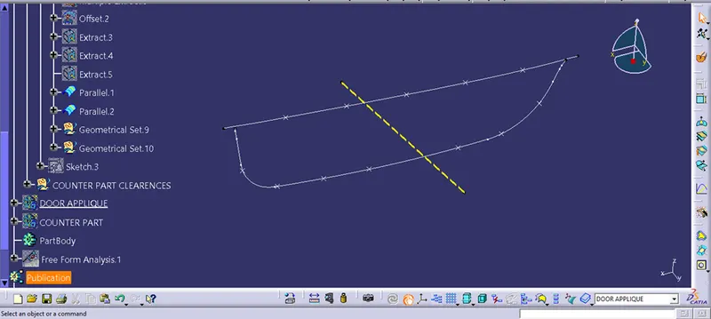
Now the sketch is drawn of the heat stakes on the one point with the outer diameter 7mm and the inner diameter 5mm and is pad in the downward direction and then the draft of 0.5mm is given as shown in the figure below.
The design rules of the heat stakes :-
There should be minimum of 50mm gap between two heat stakes.
Here also there is no rule for the diameter of the heat stakes unless and until the sink mark is form in Class A Surface.
Here the outer diameter is taken as 7mm so the inner diameter will be
The thickness of the component is 2.5mm so,
2.5/2= 1.25mm one side wall
So it will be 1.25+1.25+2.5= 5mm the inner hole diameter.
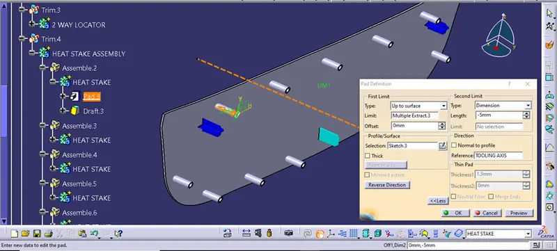
Now this heat stake, pad is copied and is paste special as a result link and then it is translated along all the points as shown in the figure below.
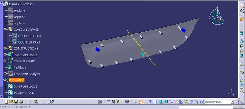
Now the door applique is fully designed along with the engineering features. So now our next task is to design the counterpart clearances. So initially the thickness of 2mm is provided to the counterpart as shown in the figure below.
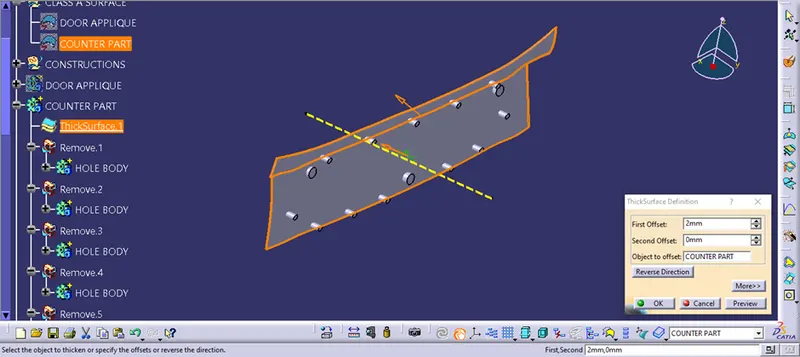
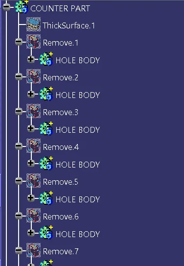
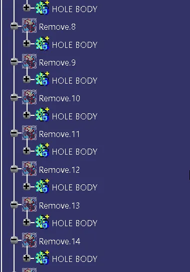
Now for the clearance initially the locator sketch is copied and is paste into the new sketch, and according to the design rules for the locators 0.1 mm should be the clearance so 15.2 mm circle is drawn and is pad in the downward direction. This same process is done along with all the locators and then finally the counter part is defined in work and then the pad is removed from the counterpart as shown in the figure below.
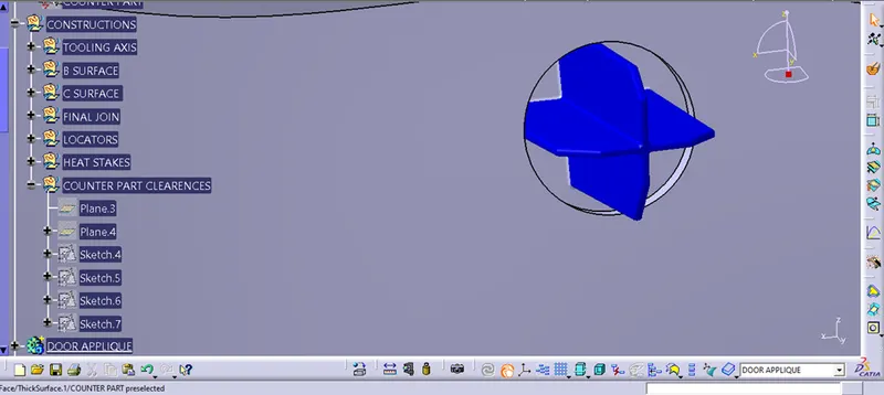
The same is the process with the heat stakes but here only one time pad is created and then this pad is paste special with result link according to the number of heat stakes and then simply it is translated and finally it is removed from the counterpart as shown in the figure below.
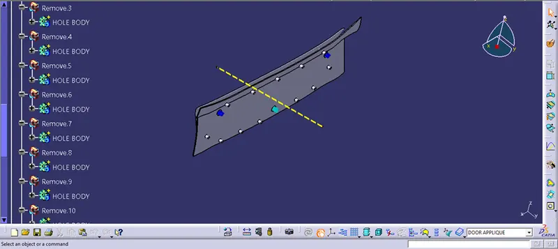
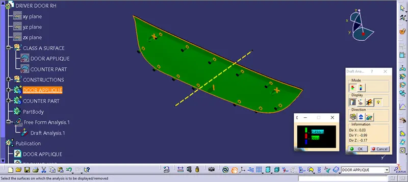
The draft analysis is also performed on to the engineering features to ensure that the given draft is correct and the product can be manufactured or not.
Hence our product is fully designed and is ready to manufacture.
DRAFT ANALYSIS OF THE COMPONENT :-
Draft analysis of the door applique :-
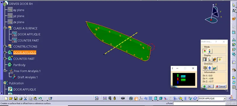
Draft analysis of the engineering features :-
IMAGES :-