Week 9 - Project 1 - Door Applique Design with Engineering Features
AIM:
Create the Door Applique Plastic component through the given Class-A surface. To begin with, the tooling axis for the given Class-A Surface should be created meeting the requirements of the draft angle and at the end perform the Draft analysis on the model.
OBJECTIVE:
- Creating tooling axis
- Creating Class-B surface
- Creating Class-C surface
- Create locators
- Create heat stakes
- Draft analysis
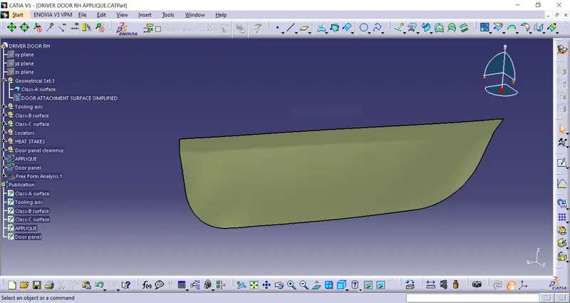
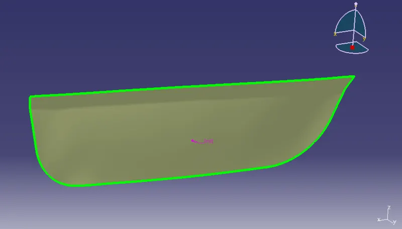
Given Class-A surface:
First I need to check whether the surface has some boundary irregularities and any open boundaries.
Tooling axis creation:
The Tooling Direction is basically the direction that the mold pulls apart. The mold is built in two separate pieces, basically. You have a Cavity side and you have the Core side. The Core pulls apart from the Cavity and that's the Dyeline or the Tooling Direction.
- analyzing the model visually to see the most efficient side suitable for the tooling axis from the image below image.
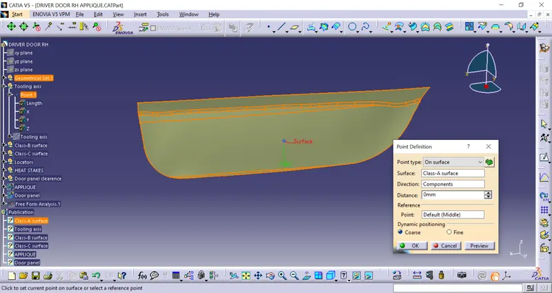
- Create a point on the class-A surface at 0mm.
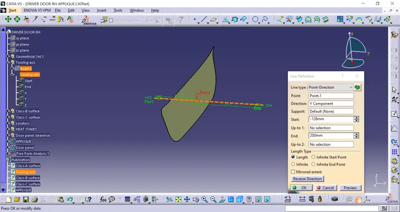
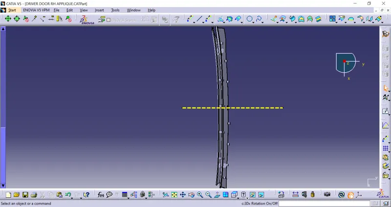
- Create an axis line towards Y direction
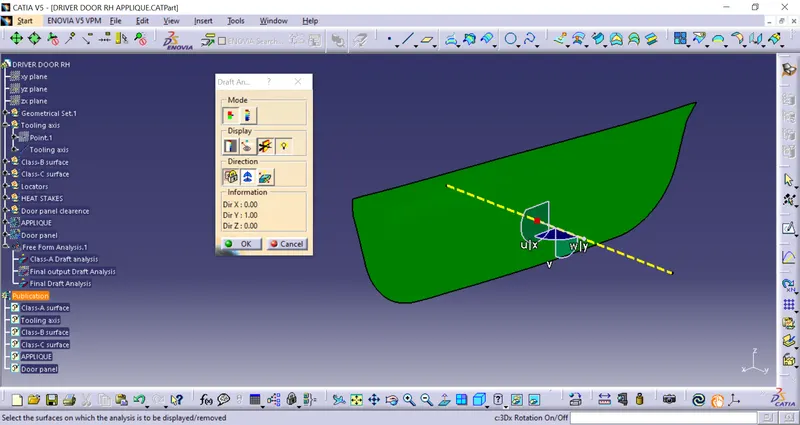
Now perform draft analysis to check whether the tooling axis has some negative draft
Creation of Class-B surface:
By extracting the Class-A surface untrimming the surface and extrapolating for trimming the surface and giving the fillets and offset distance by 2.5mm thickness which forms as the Class-B surface.
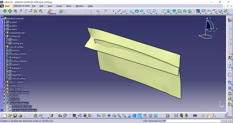
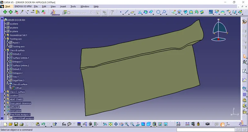
Creating Class-C surface:
By extracting the boundary from the Class-A surface required for class-C surface. sweep the boundary with respect to the class-A surface, and trim Class-A with a sweep to combine, next trim class-C surface with the class-B surface to form the final output.
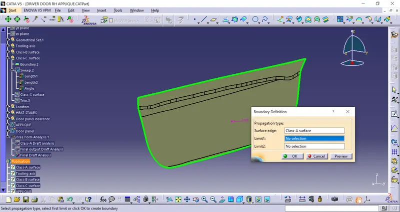
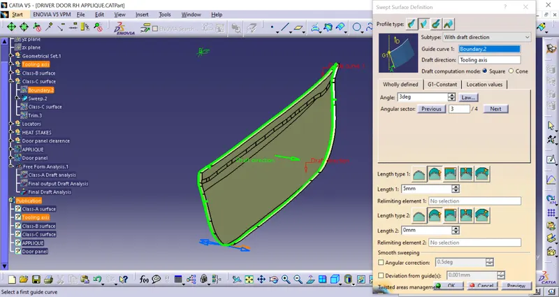
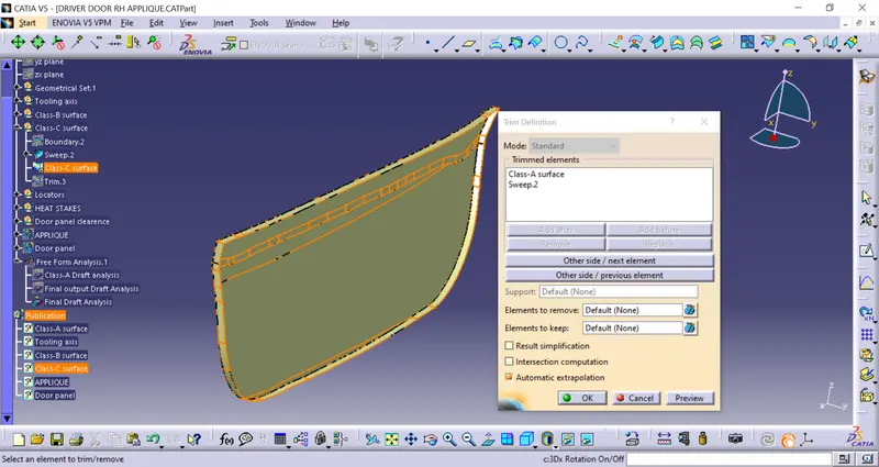
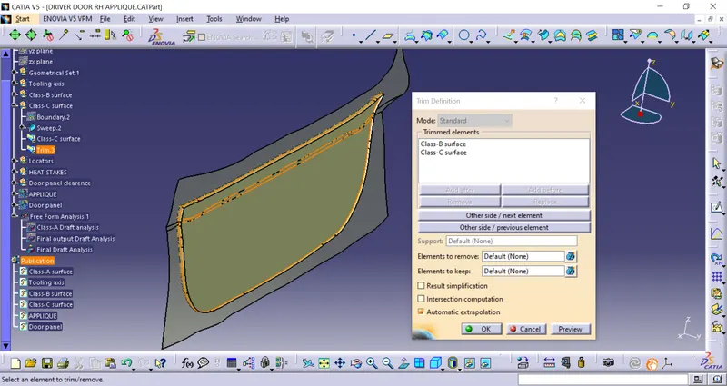
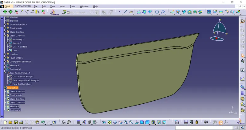
Final output:
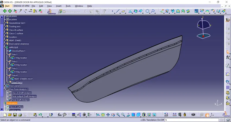
After getting the final output go to Partworkbench to convert the closed surface.
Drafting Analysis of the Final output:
- After creating the solid body we will perform the draft analysis of the whole part body.
- First, change the parameter to material mode and then go to perform draft analysis Go to Insert > analysis > feature draft analysis.
- Click on the compass icon & align with the tooling axis.
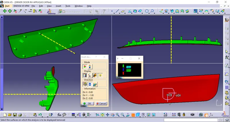
After designing the Class-B and Class-C surface we will continue to the Designing of locators
DESIGNING OF LOCATORS:
What are locators?
Locators work as The 3-2-1 principle of location (six-point location principle) is used to constrain the movement of the workpiece along the three axes XX, YY, and ZZ. This is achieved by providing six locating points. There is a total of 12 degrees of freedom, 6location, and 9 translation.
In this, I need to fix any 11 degrees of freedom permanently and anyone to be clamped or fixed temporarily.
4-Way locators and 2-Way locators
Create a plane on the surface to start a sketch.

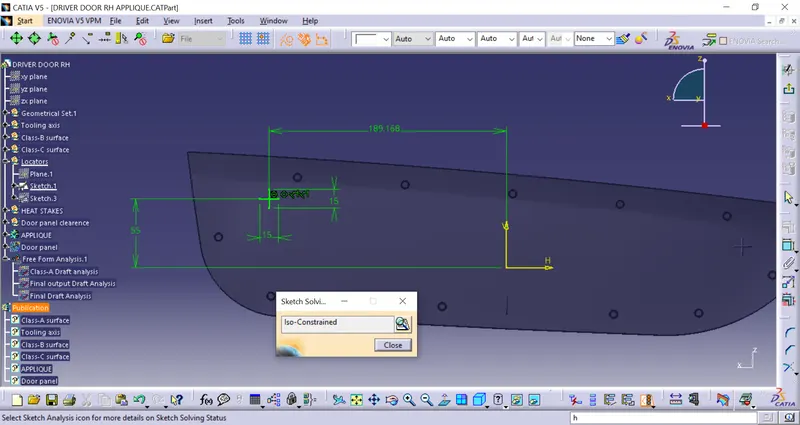
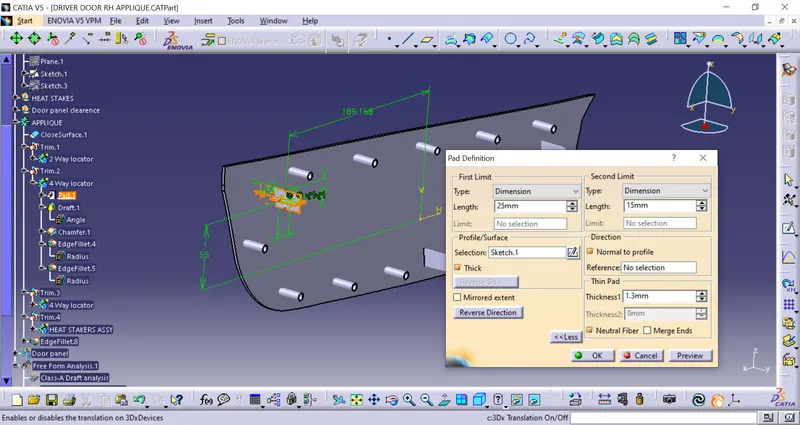
Pad the sketch for certain length on both direction
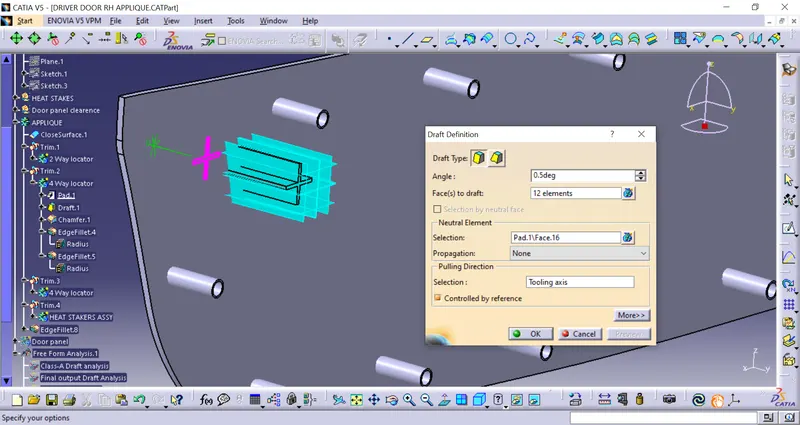
Draft the $-way locator on all direction of 0.5Degrees
Provide the chamfer of 3x45 degree
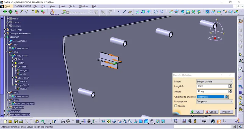
Given the radius value of 3mm on the top edges.
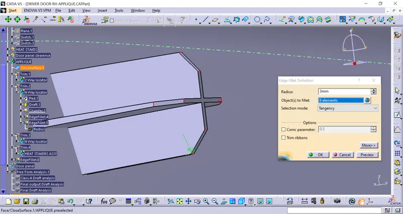
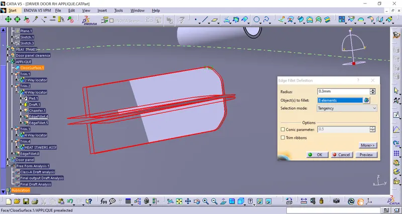
Fillet all edges around 0.5degree
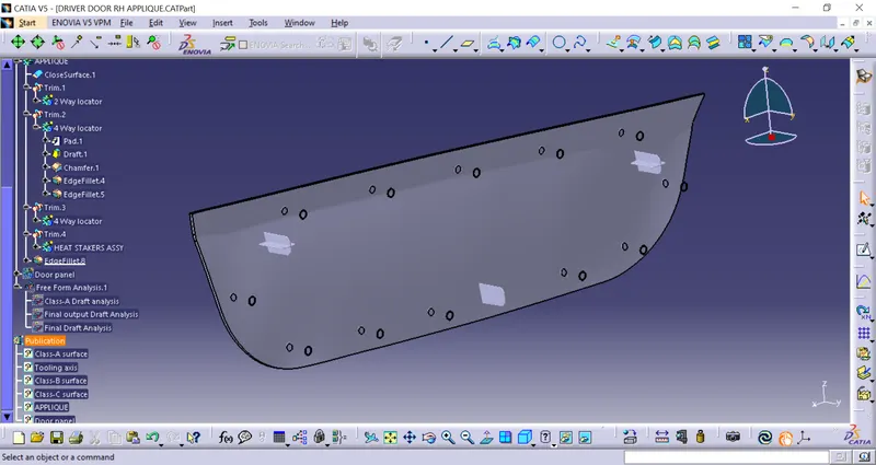
While making a locator the distance of all locators from the surface should be equal for all.
HEAT STAKING:
This is also a fixing method of a plastic component to another dissimilar or similar surface. But in this process, both of them are joined together by thermal welding and can not be removed. A boss or a stud is made on the plastic part, which is then protruded onto the opposite part and reformed after the locators are fixed.
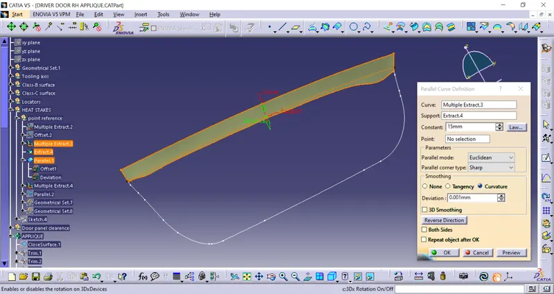
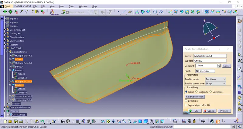
Use POINTS & REPETITION for the equal splitting of points on the parallel boundary.
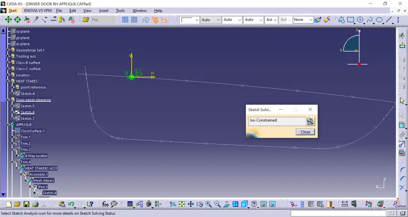
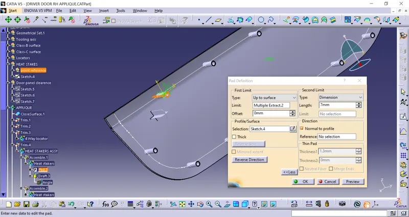
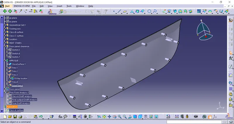
THICKEN THE DOOR ATTACHMENT SURFACE AND CREATE CLEARANCES FOR LOCATORS AND HEAT STAKES
Thicken the door attachment surface by 2mm in part workbench.
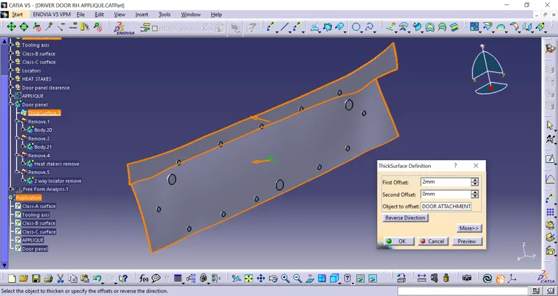
Now the locator sketch copies the sketch into a new geometrical set and draws a circle and makes the old sketch as construction lines were making the clearance for locators.
Pad the circle to an offset distance below the door attached surface and draft to 0.5degrees.
by boolean operation remove the pad from the thickened surface. so the clearance gap between the wall and the clearance wall should be 1mm to lock the motion.
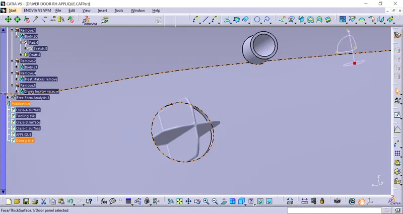
Do the same process for the remaining locators and heat stakes by creating the clearance gaps where the clearance gap for the heat staker be 1mm.
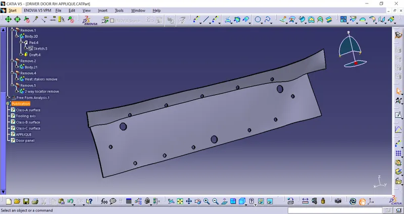
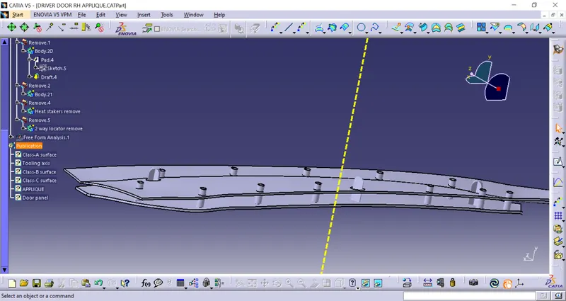
Drafting Analysis:
- After creating the solid body we will perform the draft analysis of the whole part body.
- First, change the parameter to material mode and then go to perform draft analysis Go to Insert > analysis > feature draft analysis.
- Click on the compass icon & align with the tooling axis.
various orientations of (Isometric, Front, Side, and Top View)
Isometric view:
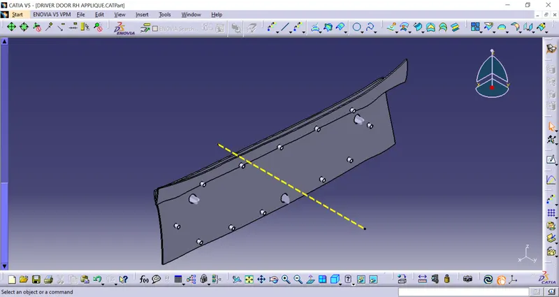
Right side view
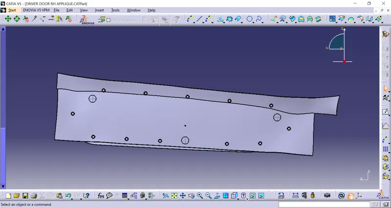
Front side view:
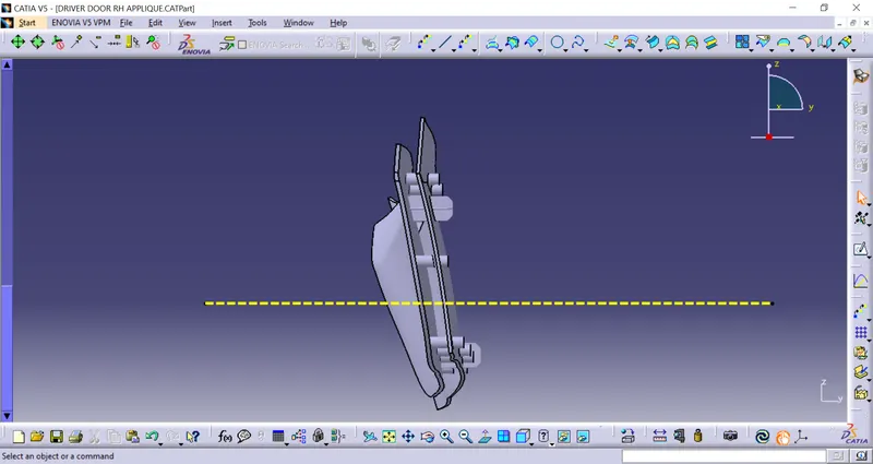
Top view:
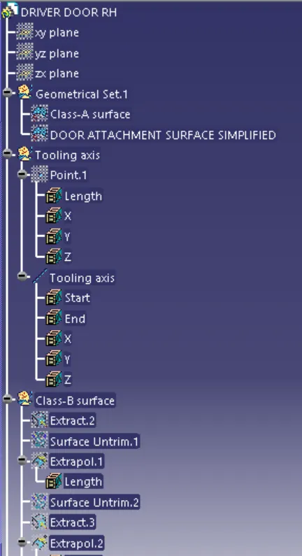
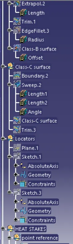
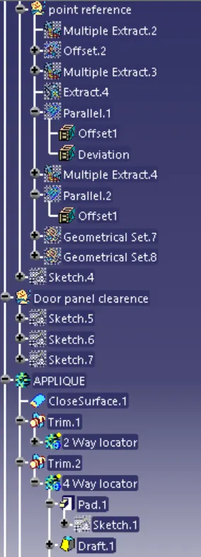
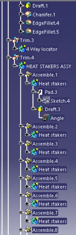
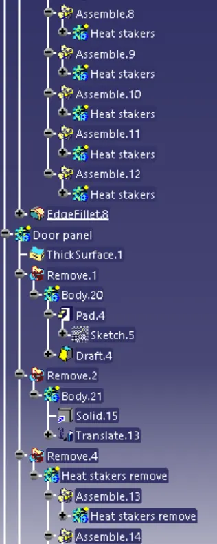
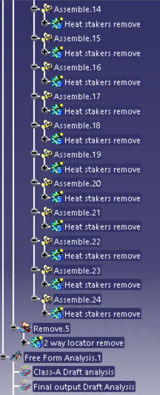
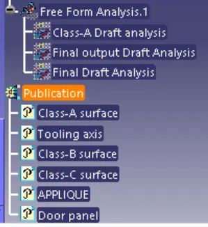
TREE STRUCTURE: