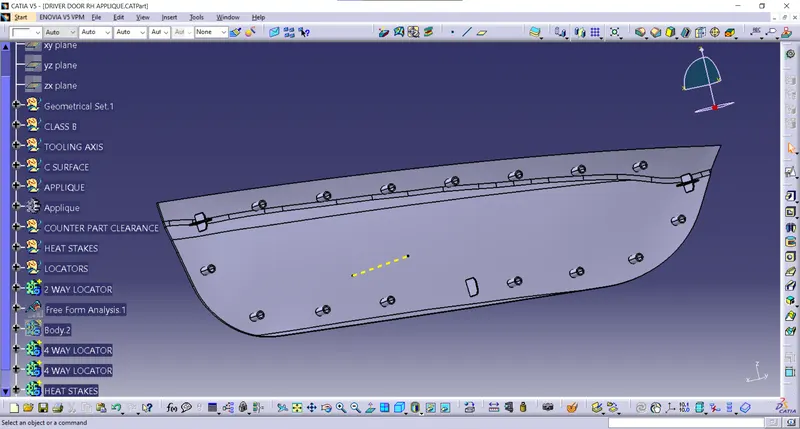
Week 9 - Project 1 - Door Applique Design with Engineering Features
Objective:- Objective of this challenge is to Creation of Door Applique Design with Engineering Features and add thickness to it using CATIA Software. And also create Class A surface, Class B surface and Class C surface and Solid Pattern for manufacturing.
Tooling Axis:- The direction in which mold opens or Core and cavity get separated, is called the Tooling axis.
Class A Surface:- It is a surface that we get as input from Alias software.
Class B Surface:- It is a surface that we create at offset thickness from Class A surface.
Class C Surface:- It is a surface that we create to join Surface A and Surface B.
I've created the tooling axis by point and direction method.
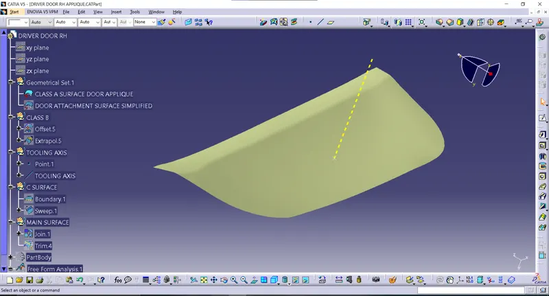
CLASS A surface is given as input so I offset it to 2.5mm, to get B surface.
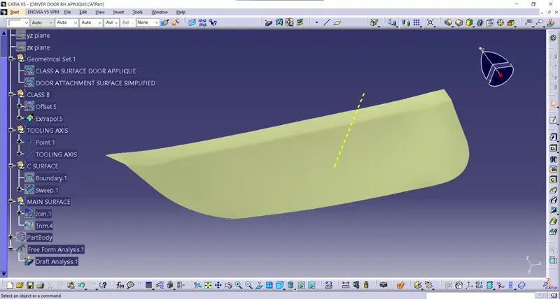
I've took the boundary of A surface and swept it in tooling direction with draft angle.
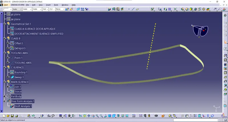
Trimmed A, B and C surface using trim command.
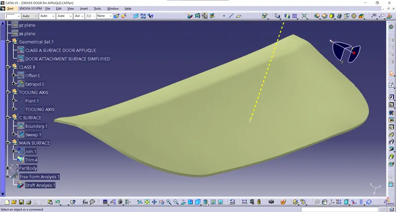
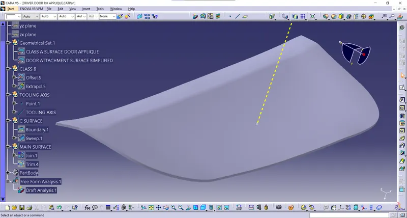
Created a solid applique using close surface command.
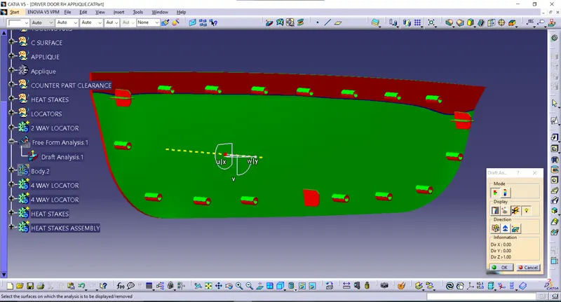
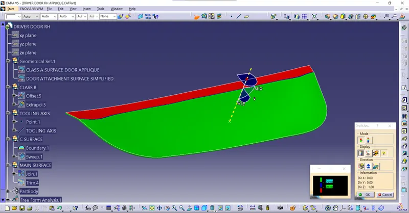
Draft analysis in tooling direction
Final Applique
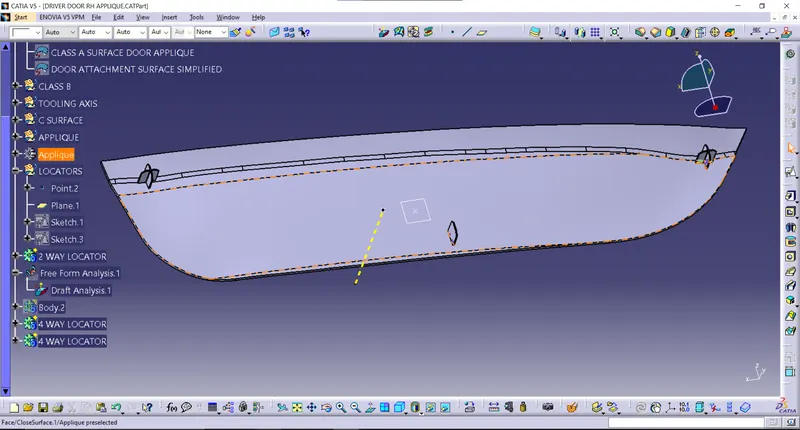
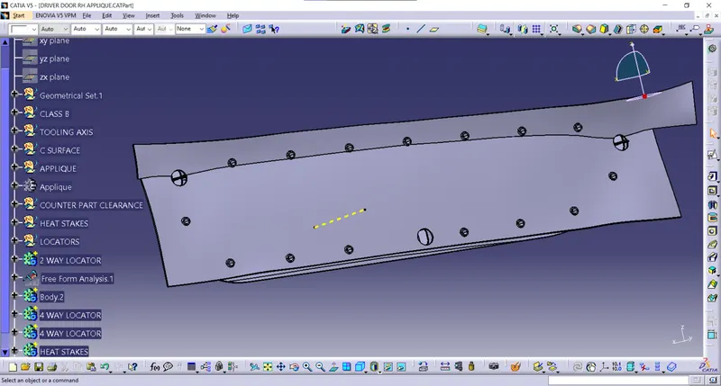
Created 2 4-WAY locator and One 2-WAY locator to restrict the movement
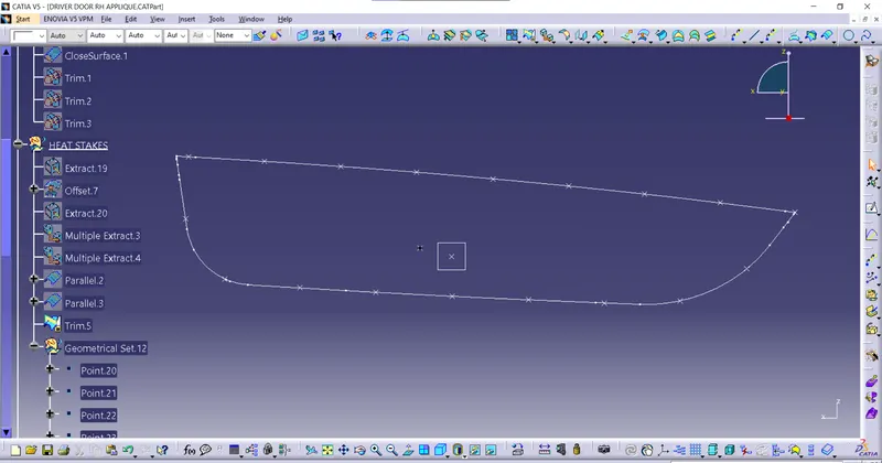
By parallel cureve created points for Heat stakes.
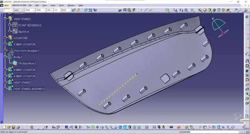
Created heat stakes by padding th circles.

Different view
Created clearance for 2-WAY, 4-WAY locator and heat stakes by padding the cicle and then removing from door surface.
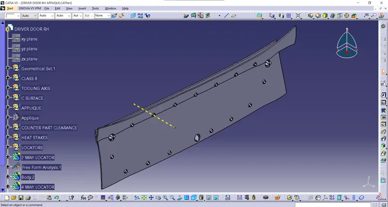
Different view
Final product