Photo Realistic Rendering
Title:- Modelling of American Chopper Bike
Objective:- The main objective of this project was to get command on SOLIDWORKS. In this course, I've learnt many basic and advanced command of SOLIDWORKS. Some of the key-points of this project are below mentioned:-
- To do part Modelling of different parts.
- To learn the sketching concept.
- To learn how to ideate any project.
- To learn the assembly of different parts.
- To learn different types of mates.
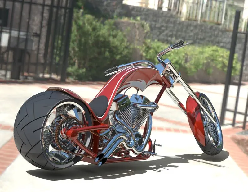
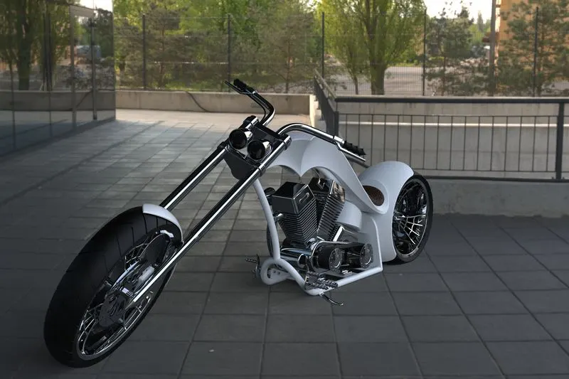
- To do a photo-realistic rendering of the American Chopper Bike.
Introduction:- American Chopper Bike started in 2003 and was one of the most popular motorcycling shows. It focuses on Paul Teutul Sr, his son Paul Teutul Jr, and their company, Orange County Choppers. It is located in Orange County, New York, and was founded in 1999. They focus on restorations and customizations of choppers built in the US.
It was interesting mostly because of the differences between the visions and styles between father and son. Intense arguments and fights were regular. Of course, they made some great bikes over the years.
Design Methodology:-
Flowchart
- Part Modelling:- In part Modelling, I've modelled 13 below mentioned parts:-
- Transmission Belt
- Kickstand
- Pedal
- Chassis
- Front Fender
- Rear Fender
- Front Fork
- Front Wheel
- Rear Wheel
- Oil Tank
- Chain
- Gas Tank
- Engine
I've used different tools for modelling like sketch, extruded boss, revolved boss, swept boss, lofted boss, extruded cut, revolved cut, swept cut, lofted cut, fillet, chamfer, linear pattern, circular pattern, shell, mirror, dome etc. I've also used some surface features for modelling of some parts.
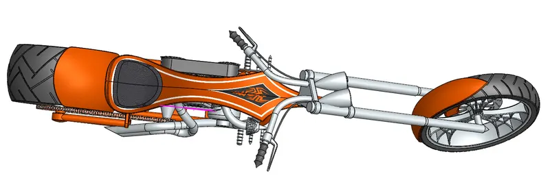
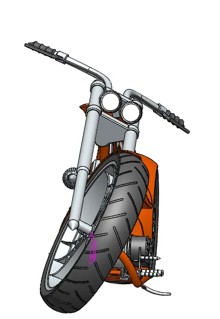
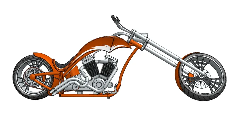
- Assembly:- I've Assembled those 13 modelled parts using a different kind of mates and features. I've used coincident mate, concentric mate, distance mate, limit angle mate, width mates, angle mate, parallel mate, tangent mate etc. mates for assembly of American Chopper Bike. I've also used mirror function to mirror some parts in the assembly.
- Photo-realistic rendering:-
Title:- Modelling of American Chopper Bike
Objective:- The main objective of this project was to get command on SOLIDWORKS. In this course, I've learnt many basic and advanced command of SOLIDWORKS. Some of the key-points of this project are below mentioned:-
- To do part Modelling of different parts.
- To learn the sketching concept.
- To learn how to ideate any project.
- To learn the assembly of different parts.
- To learn different types of mates.
- To do a photo-realistic rendering of the American Chopper Bike.
Introduction:- American Chopper Bike started in 2003 and was one of the most popular motorcycling shows. It focuses on Paul Teutul Sr, his son Paul Teutul Jr, and their company, Orange County Choppers. It is located in Orange County, New York, and was founded in 1999. They focus on restorations and customizations of choppers built in the US.
It was interesting mostly because of the differences between the visions and styles between father and son. Intense arguments and fights were regular. Of course, they made some great bikes over the years.
Design Methodology:-
Flowchart
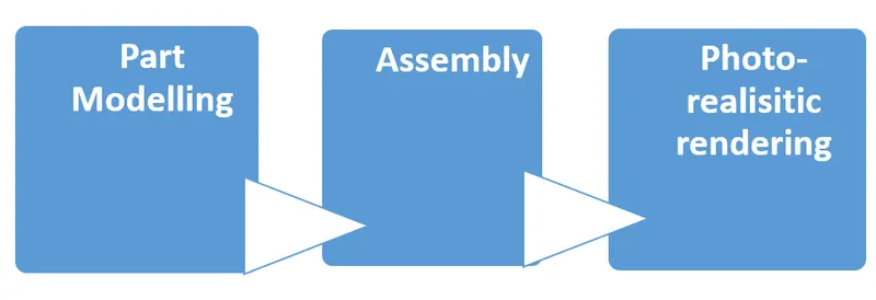
- Part Modelling:- In part Modelling, I've modelled 13 below mentioned parts:-
- Transmission Belt
- Kickstand
- Pedal
- Chassis
- Front Fender
- Rear Fender
- Front Fork
- Front Wheel
- Rear Wheel
- Oil Tank
- Chain
- Gas Tank
- Engine
I've used different tools for modelling like sketch, extruded boss, revolved boss, swept boss, lofted boss, extruded cut, revolved cut, swept cut, lofted cut, fillet, chamfer, linear pattern, circular pattern, shell, mirror, dome etc. I've also used some surface features for modelling of some parts.
- Assembly:- I've Assembled those 13 modelled parts using a different kind of mates and features. I've used coincident mate, concentric mate, distance mate, limit angle mate, width mates, angle mate, parallel mate, tangent mate etc. mates for assembly of American Chopper Bike. I've also used mirror function to mirror some parts in the assembly.
- Photo-realistic rendering:- Rendering is a process after which we got an image of real view of the product i.e. after rendering of bike I can see how it will look like in reality after manufacturing. There are different tools available for rendering but I've used Photoview 360, SOLIDWORKS Visualize and Key shot. In rendering different settings of the scene, decals, environment and camera should be done.
Description:- In this section, I'll explain How I modelled different parts in SOLIDWORKS.
- Transmission Belt:- It is used to transmit the power from driver pulley to driven pulley. Generally, it is made up of rubber. Here is an image of Transmission Belt:-
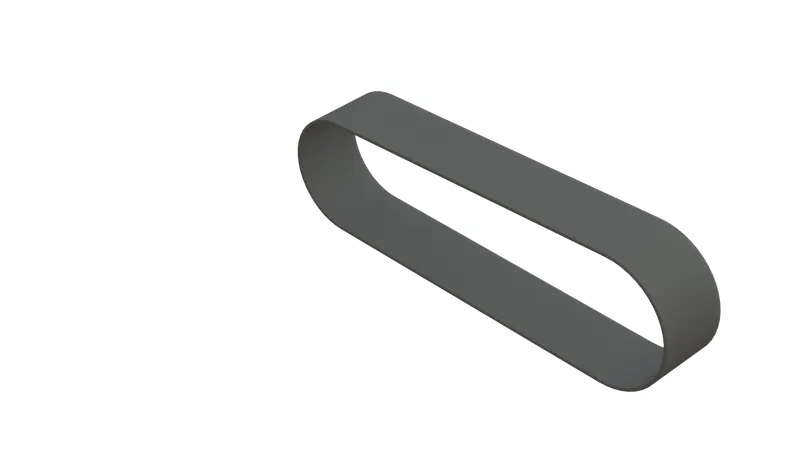
Features Used:- I've used the following features in modelling of Transmission Belt:-
1. Slot
2. Offset
3. Extruded Boss/Base
4. Fillet
5. Material apply
Procedure:- First I've selected Front plane for 2D sketching, after that on that plane I've created a 2D slot. Then I've applied dimension to it, then I've extruded it, then I've applied fillet at sharp edges. And At last, I've applied material and appearance and then rendered it and saved it.
2. Kickstand:- Kickstand is used to support the bike in a stationary condition. It is used to put the bike stable on the ground without human support. It is a lever mechanism. It is generally made of metal as it has to bear the weight of the vehicle. Here is an image of the kickstand:-
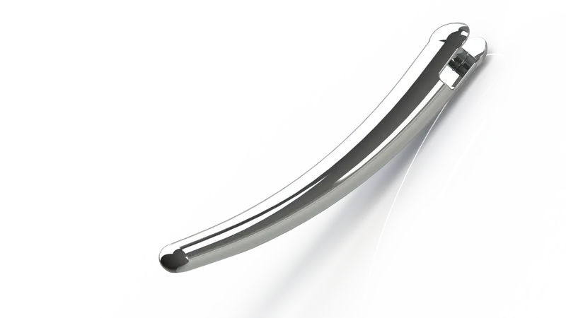
Features Used:- I've used the following features in modelling of Kickstand:-
1. Reference Plane
2. Ellipse
3. Lofted Boss
4. Dome
5. Cut Extrude
6. Split
7. Extruded Boss
8. Fillet
Procedure:- First I've selected Front plane for an offset plane building and 2D sketching, after that on Front plane and newly created plane plane1 I've created ellipse. Then I've applied dimension to it, then I've created a guided curve on top plane then I've lofted 2 ellipses through guided curve, then I've applied Dome at elliptical edges. Then I've created a cut extrude on big elliptical size to give it movement, then I split to create a flat bottom on small elliptical side and then I've applied fillets at sharp edges. And At last, I've applied material and appearance and then rendered it and saved it.
3. Pedal:- It is used as a footrest. It is also used for rear brakes. It is generally spring-loaded. It is made up of metal. Here is an image of the Pedal:-
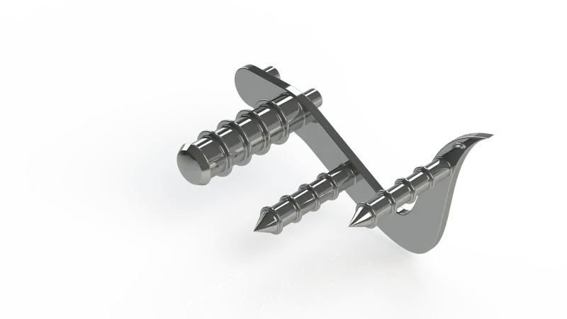
Features Used:- I've used the following features in modelling of Pedal:-
1. Sketch
2. Boss-Extrude
3. Fillet
4. Revolve
5. Dome
6. Chamfer
7. Linear Pattern
Procedure:- First I've made the sketch on the front plane than using above given features I've modelled this pedal.
4. Chassis:- Chassis is a major support system of any vehicle. It provides support to the fuel tank, engine, gas tank, seat etc. It is generally made up of metal. Here is an image of Chassis:-
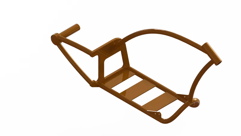
Features Used:- I've used the following features in modelling of Chassis:-
1. Projected Curve
2. Swept Extrude
3. Mirror
4. Boss Extrude
5. Cut Extrude
6. Chamfer
7. Fillet
8. Dome
9. Reference Plane
10. Split
11. Combine
12. Revolved Boss
13. Sketch
Procedure:- First I've made the sketch on the midplane than using above given features I've modelled this Chassis.
5. Front Fender:- Front fender is used to protect the driver from mud and dirt. It is made up of metal. It also protects tires from external damage. Here is an image of front fender:-
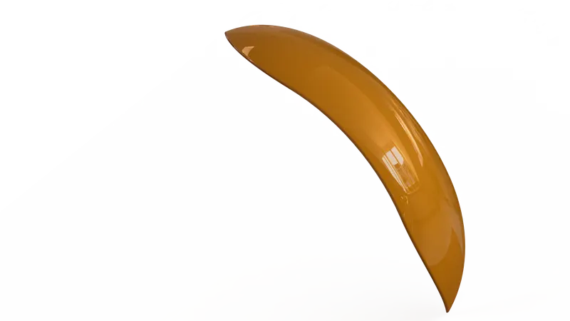
Features Used:- I've used the following features in modelling of Front Fender:-
1. Sketch
2. Revolved Boss
3. Split
4. Fillet
Procedure:- First I've made the sketch on the right plane than using above given features I've modelled this Front Fender.
6. Rear Fender:- Rear fender is used to protect the driver from mud and dirt. It is made up of metal. It also protects tires from external damage. Here is an image of rear fender:-
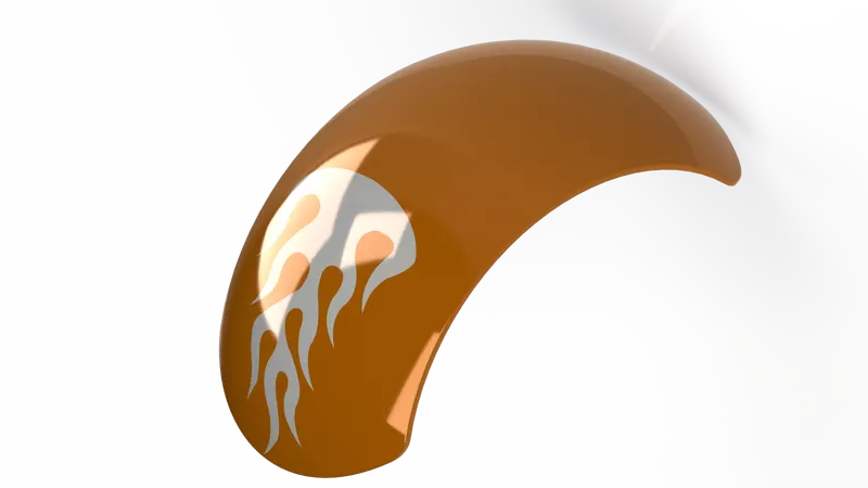
Features Used:- I've used the following features in modelling of Rear Fender:-
1. Sketch
2. Revolved Boss
3. Split
4. Fillet
5. Shell
Procedure:- First I've made the sketch on the right plane than using above given features I've modelled this Rear Fender.
7. Front Fork:- Front fork is used to steer the vehicle. It helps, in turn, the vehicle in the required direction. It is made up of metal. It also supports to hand for rest. Here is an image of Front Fork:-
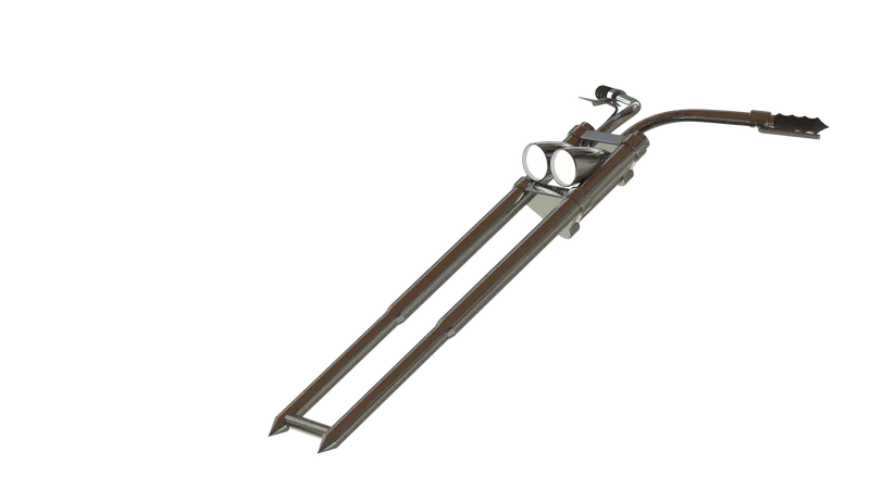
Features Used:- I've used the following features in modelling of Front fork:-
1. Sketch
2. Revolved Boss
3. Extruded Boss
4. Fillet
5. Linear Pattern
6. Extruded Cut
7. Dome
8. Revolved Cut
9. Move body
10. Projected Curve
11. Swept Boss
12. Reference Plane
13. Mirror
14. Combine
Procedure:- First I've made the sketch on the Front plane than using above given features I've modelled this Front Fork.
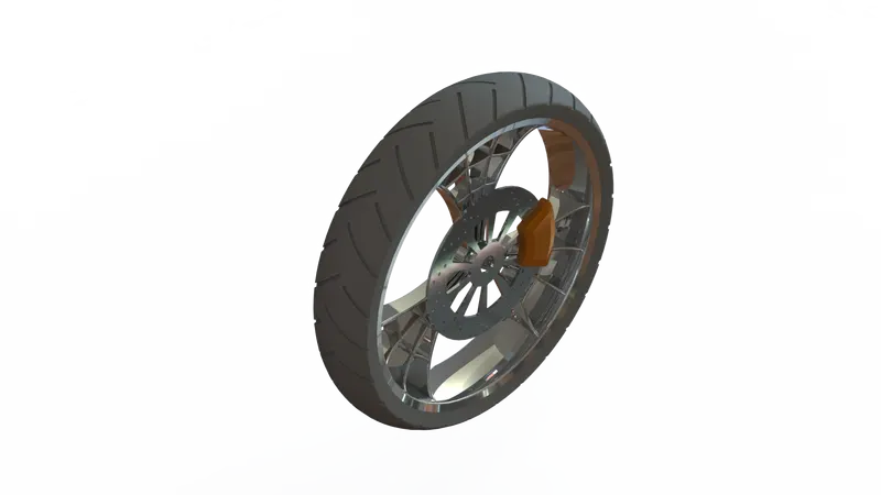
8. Front Wheel:- Front-wheel is used to support the front part of the vehicle. It consists of the disc, caliper, rim, and tire. The tire is made up of rubber. Rim is made up of steel. Caliper is made of metal and rubber. The disc is made up of metal. Here is an image of Front Wheel:-
Features Used:- I've used the following features in modelling of Front wheel:-
1. Sketch
2. Revolved Boss
3. Extruded Boss
4. Fillet
5. Circular Pattern
6. Extruded Cut
7. Combine
8. Revolved Cut
9. Chamfer
Procedure:- First I've made the sketch on the Front plane than using above given features I've modelled this Front Wheel.
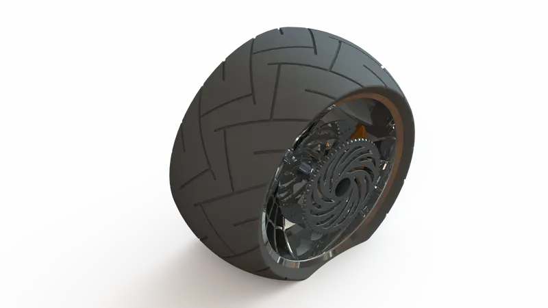
9. Rear Wheel:- Front-wheel is used to support the rear part of the vehicle. It consists of the disc, caliper, rim, sprocket, and tire. The tire is made up of rubber. Rim is made up of steel. Caliper is made of metal and rubber. The disc is made up of metal. The sprocket is made up of metals and it has teeth on its circumference. Here is an image of the Rear Wheel:-
Features Used:- I've used the following features in modelling of Rear wheel:-
1. Sketch
2. Revolved Boss
3. Extruded Boss
4. Fillet
5. Circular Pattern
6. Extruded Cut
7. Combine
8. Revolved Cut
9. Chamfer
10. Combine
Procedure:- First I've made the sketch on the Front plane than using above given features I've modelled this Rear Wheel.
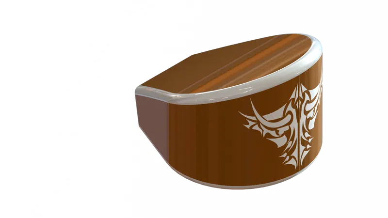
10. Oil Tank:- Oil tank is used to store the oil fuel for the vehicle. It is made up of metal. Here is an image of the Oil tank:-
Features Used:- I've used the following features in modelling of Oil Tank:-
1. Sketch
2. Combine
3. Extruded Boss
4. Fillet
5. Shell
Procedure:- First I've made the sketch on the Top plane than using above given features I've modelled this Oil Tank.
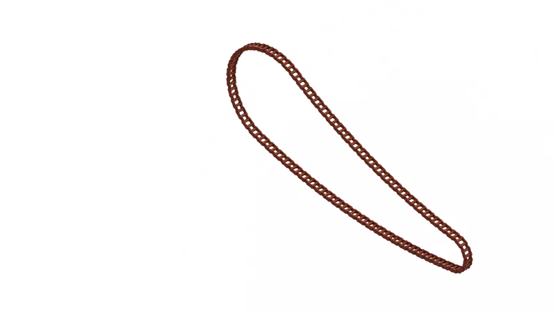
11. Chain:- Chain is used to transmit power from the engine to rear wheel vehicle. It contains many small links which are connected by pins. It is made up of metal. Here is an image of the Chain:-
Features Used:- I've used the following features in modelling of Chain:-
1. Sketch
2. Curve driven pattern
3. Extruded Boss
4. Fillet
5. Shell
6. Mirror
7. Delete body
Procedure:- First I've made the sketch on the midplane than using above given features I've modelled this Chain.
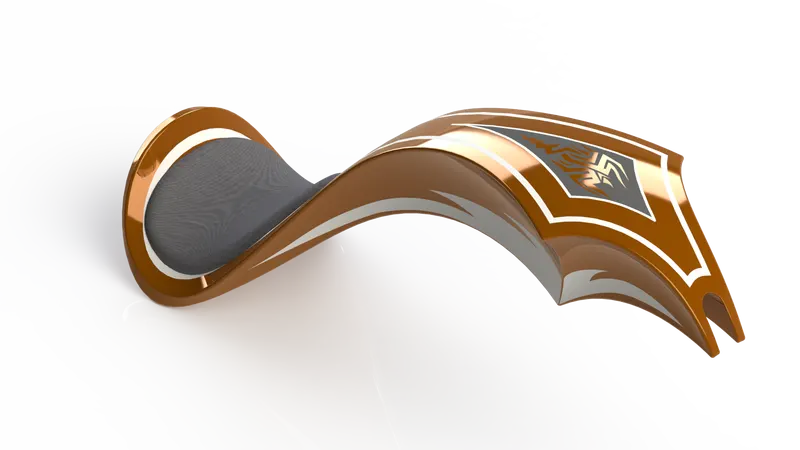
12. Gas Tank:- The gas tank is used to store the gas fuel for the vehicle. It consists of a gas tank and seat. The gas tank is made up of metal. The gas tank is made up of foam and rexine. Here is an image of the Gas tank:-
Features Used:- I've used the following features in modelling of Gas tank:-
1. Sketch
2. Swept Surface
3. Boundary Surface
4. Fillet
5. Surface Trim
6. Split Line
7. Surface knit
8. Boundary Surface
9. Surface Loft
10. Swept Cut
11. Shell
Procedure:- First I've made the sketch on the midplane than using above given features I've modelled this Chain.
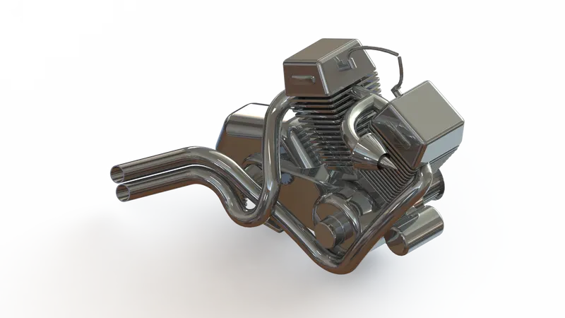
13. Engine:- Engine is used to generate power for running the vehicle. It is a 2 cylinder engine. It has to do 4 processes suction, compression, combustion and exhaust. It consists of a cylinder, exhaust, starter motor and fuel lines. It is made up of metal. Here is an image of the Engine:-
Features Used:- I've used the following features in modelling of Engine:-
1. Sketch
2. Extruded Boss
3. Fillet
4. Revolved Boss
5. Reference Plane
6. Circular Pattern
7. Dome
8. Extruded cut
9. Chamfer
10. Linear Pattern
11. Mirror
12. Split
13. Swept Boss
14. Combine
15. Projected Curve
16. Composite curve
Procedure:- First I've made the sketch on the Front plane than using above given features I've modelled this Engine.
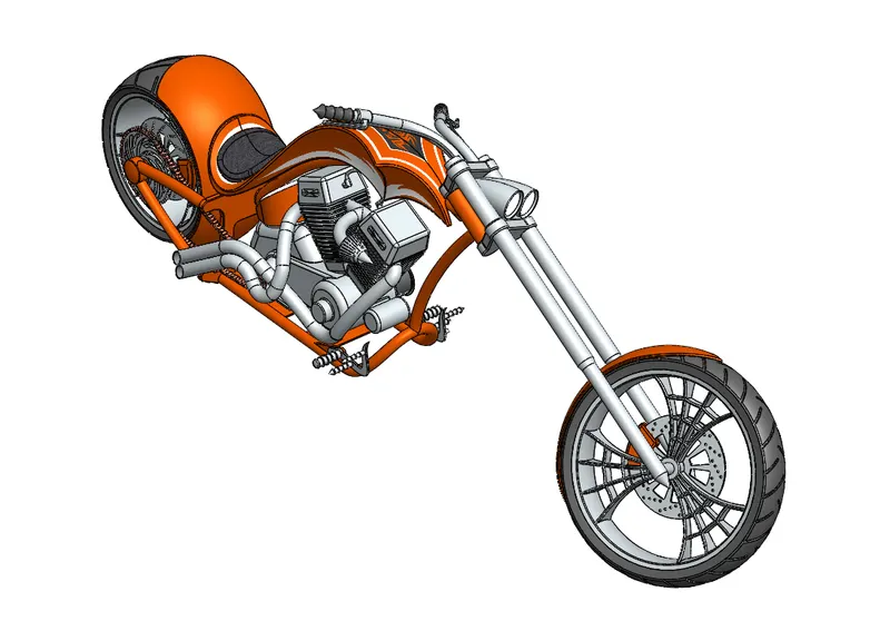
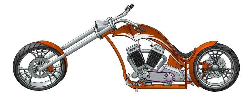
Assembly:- After modelling these 13 parts I have assembled them using different mates. I have assembled them in the following sequence.
Chassis => Engine => Pedal => Kickstand => Transmission belt => Oil tank => Rear wheel => Rear fender => Chain => Gastank => Front fork => Front wheel => Front fender.
I have used the following mates for assembly:-
- Coincident mate
- Distance mate
- Concentric mate
- Limit angle mate
- Width mate
- Angle mate
- Parallel mate
- Tangent mate
Here are some snapshot of assembly:-
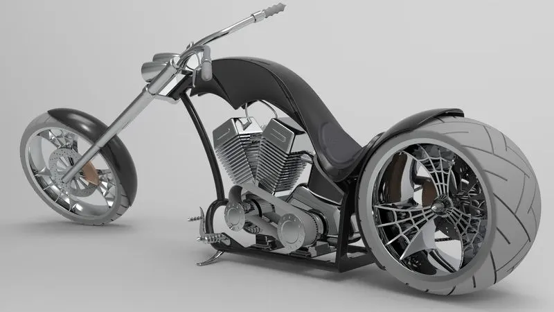
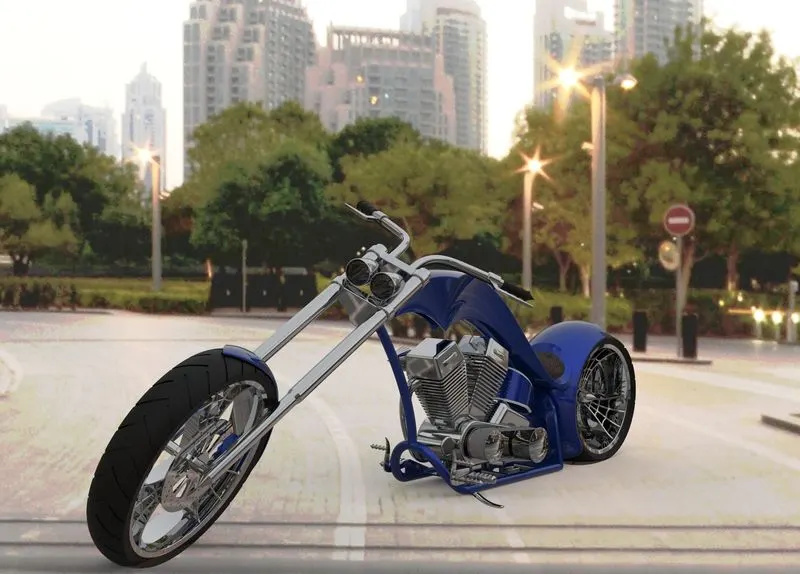
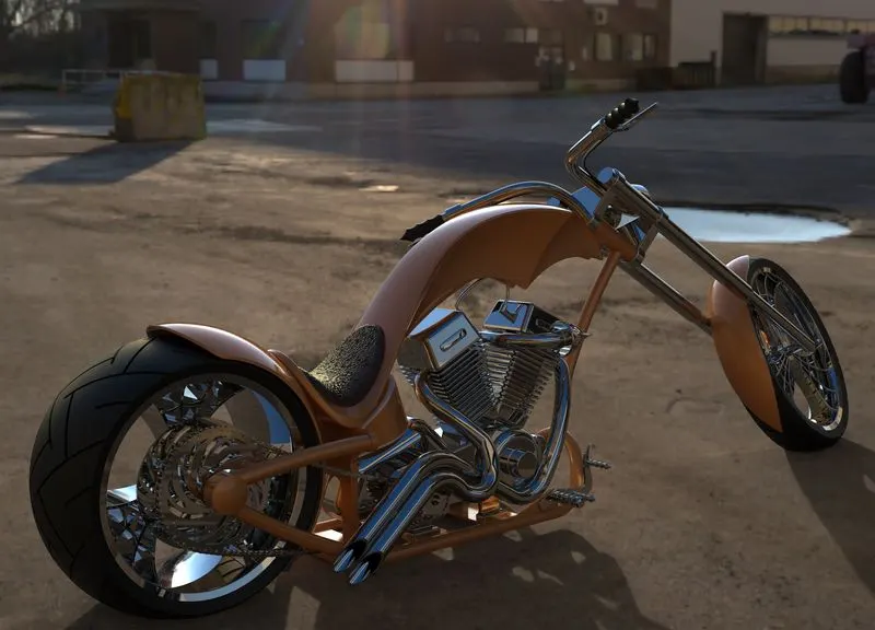
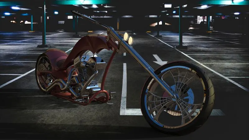
Here are some rendered images of the bike:-
Conclusion:- In this project I have learnt about many features of SOLIDWORKS. I have learnt Boss extrude, Sketch making, Swept, Loft, Fillet, chamfer, dome, mirror, pattern etc. It will help me in my next project of designing.