Week 8 - Challenge 1 - Draft Analysis on a Fan Cover
Objective:- Objective of this challenge is to do a Draft analysis of a Fan Cover using CATIA Software.
Tooling Axis:- The direction in which mold opens or Core and cavity get separated, is called the Tooling axis.
Phase 1:- In phase 1 we import Class A surface in Catia. That Class A surface may be in the different part surfaces, so we join them using JOIN Command in CATIA. For confirmation of joining we use BOUNDARY command, If boundary shows no error then we go for phase 2.
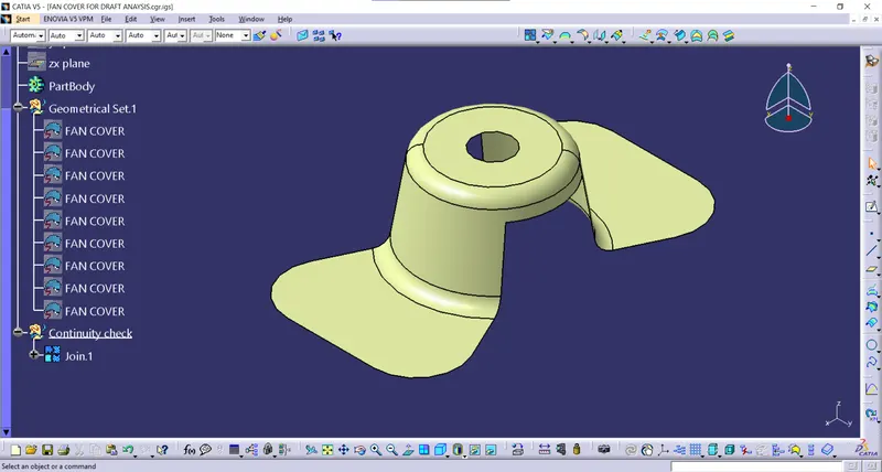
Phase 2:- In Phase 2 we create Tooling axis of the product then we do draft analysis of it.
We create a dummy tooling axis by visualizing the product. We choose dummy tooling axis such that product's manufacturing will be easy. In our Fan cover along Z axis will be our dummy tooling axis.
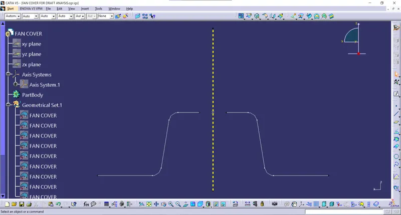
After creating dummy tooling axis, we check for clearance along different directions. In our case, it'll be along X-axis and along Y-axis. First, we'll check for Y-axis so here is image. We create intersection curve along Y-axis then check for directions parallel or angeled less than 90 to the dummy tooling axis. Then we create bisecting line using those 2 parallel lines and that will be our tooling line for the Y Intersection curve.
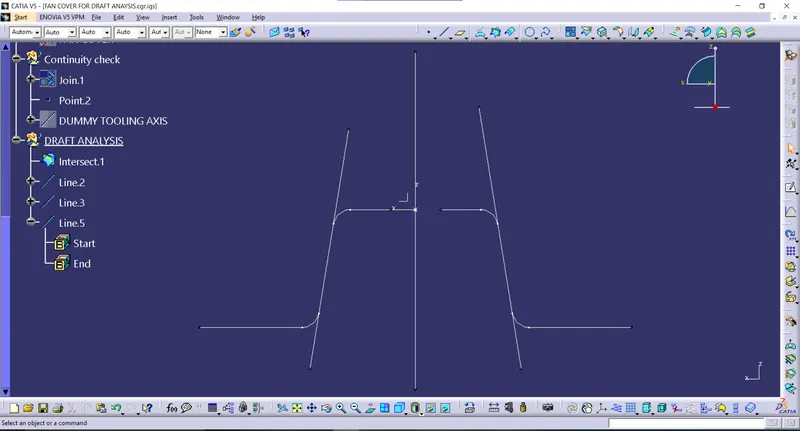
Now, we'll check for X-axis so here is image. We create intersection curve along X-axis then check for directions parallel or angeled less than 90 to the dummy tooling axis. Then we create bisecting line using those 2 parallel lines and that will be our tooling line for the X Intersection curve.
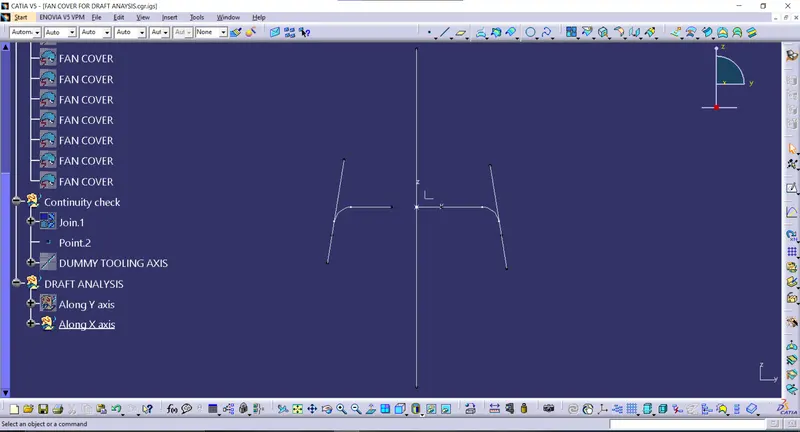
After that we create a bisecting line of X tooling Line and Y tooling line. And it'll be our Final tooling Line.
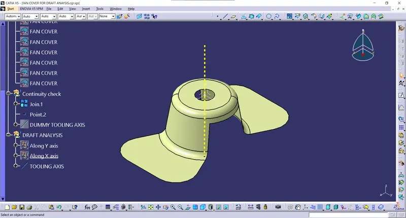
After that do the draft analysis of our product using the feature draft analysis tool. We do draft analysis for 3 Degree and here are the images of the same.
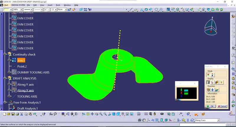
Different views of draft analised product.
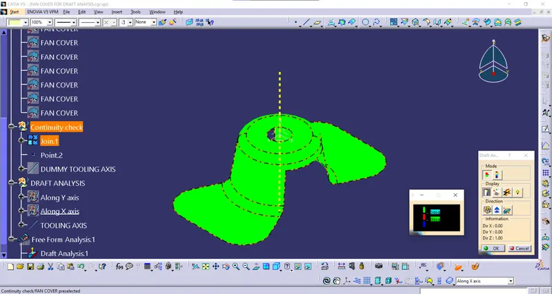
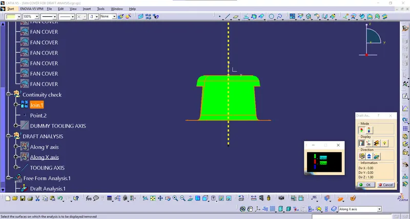
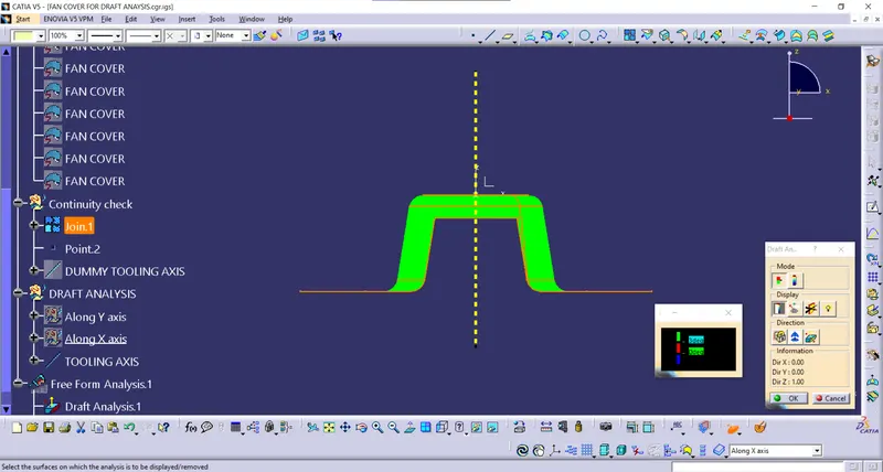
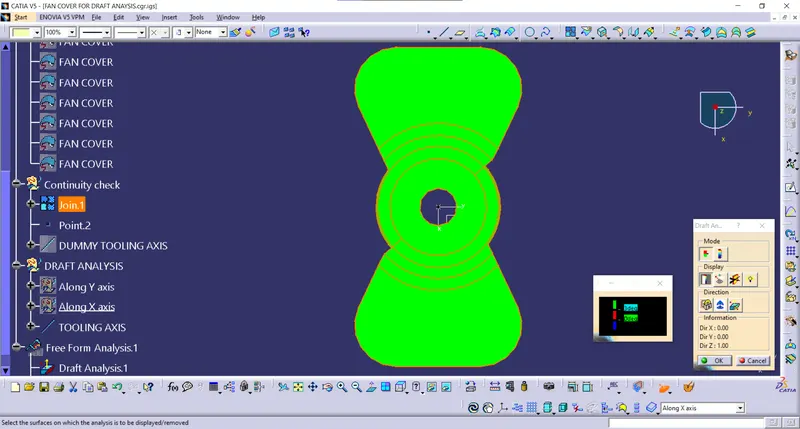
Result:- Draft analysis was successful and the product is found perfect for 3 degree draft manufacturing.