Week 9 - Project 1 - Door Applique Design with Engineering Features
DESIGN OF DOOR APPLIQUE WITH ATTACHMENT FEATURES
Objectives:
- Generate tooling axis for the given part
- Make the 3d solid part using the given class A surface using shape design
- Draft analysis of the solid model
- Design Locator pins on the B surface
- Design heat stakes
- Construct the required details on the door attachment surface
Software used: DS CATIA P3 V5 2018- PART DESIGN, GENERATIVE SHAPE DESIGN WORKBENCHES
Introduction:
The simplest form of attachment feature for a plastic part is known as heat stakes. The advantage of heat stakes over the other features is that it doesn't require additional materials or complex tools/machinery to do the assembling process. Heat stakes are simply some projections given the class B side of an object which can be joined with other parts by the application of heating. The progressive melting of the plastic under continuous pressure makes the head of the stake.
- This process helps to reduce manufacturing time and cost.
- Simplification of machinery
- Allows multiple fastening points
- Allows higher density of welds
This process can be used to attach lightweight elements or aesthetic components to their position. This project involves the construction of a door applique part and the elements required to do the heat stake joining process.
We know that, in order to fix components on position, we need to arrest all degrees of freedom. In mechanical industries, It can be done by the 3-2-1 principle. The 3-2-1 principle of location (six-point location principle) is used to constrain the movement of the workpiece along the three axes XX, YY, and ZZ. This is achieved by providing six locating points, 3 pins in the base plate, 2 pins in the vertical plane, and 1 pin in a plane that is perpendicular to the first two planes.
DESIGN METHODOLOGY:
Making the solid model using class B, class C surfaces from class A:
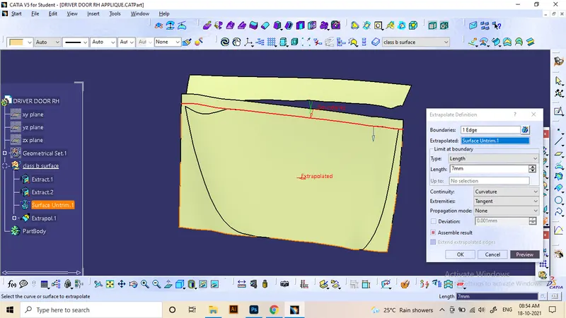
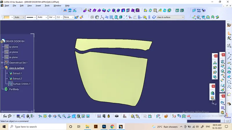
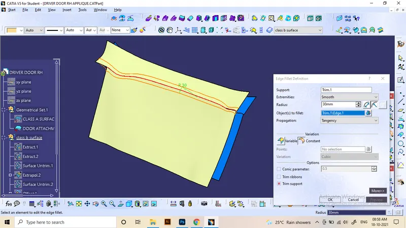
We use the method of surface design using generative shape design workbench for making the class B and C surfaces. Here the class A part constitutes 2 main surfaces that are inclined to each other and fillet of 30 mm between them.
We can use the extract, offset method to make class b surfaces
Tooling Axis:
To make proper drafts for the class C surface, we need tooling axis. Since it is a plane geometry, tooling axis can be made in the middle.
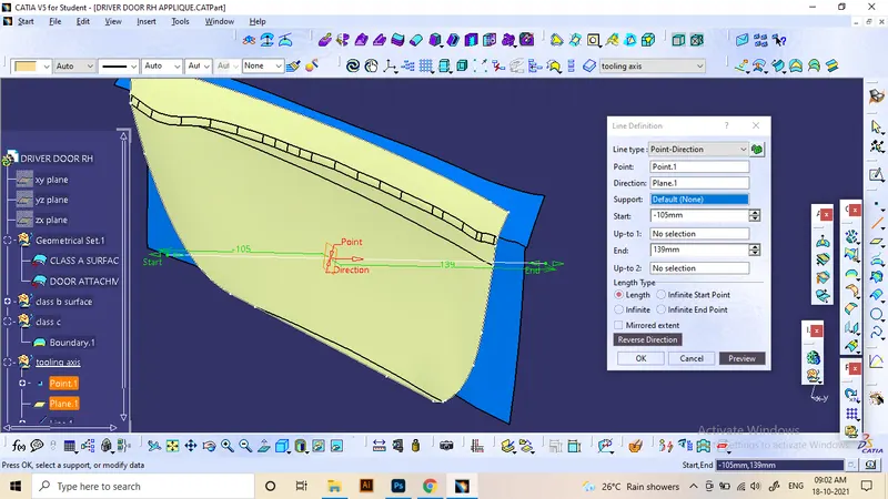
Class C parts comes at more than 3 degree draft angle at the boundaries of class A.
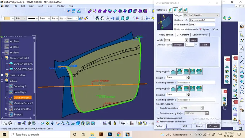
We need multiple surface patches to make class C surface. They are trimmed together.
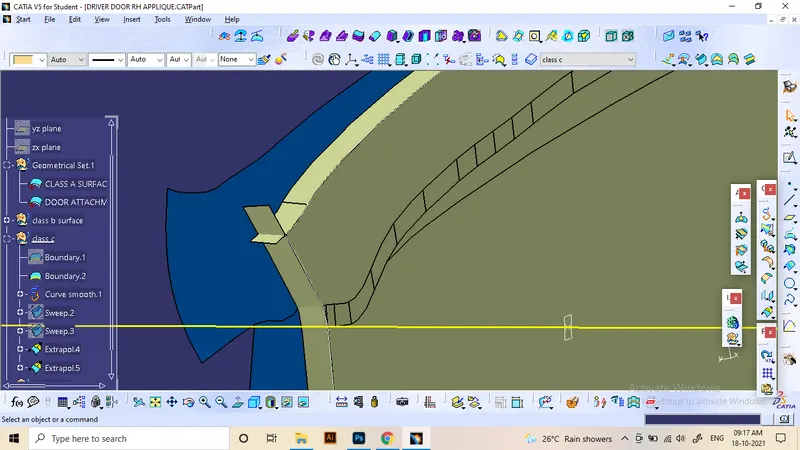
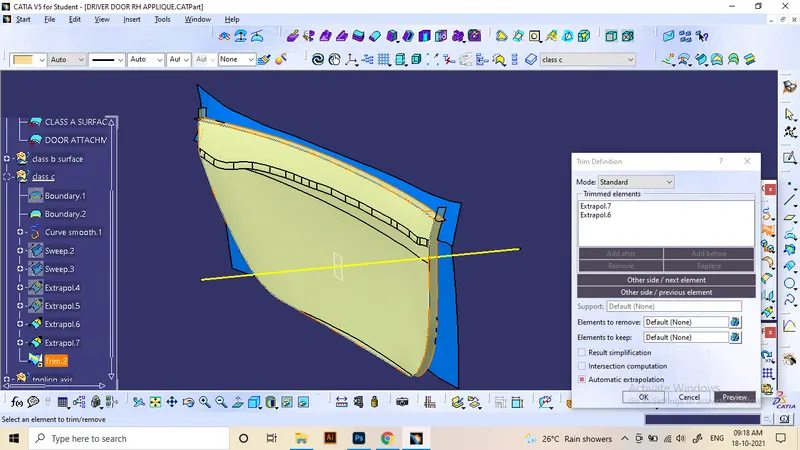
All surfaces will be trimmed into a single patch and used close surface to make solidpart.
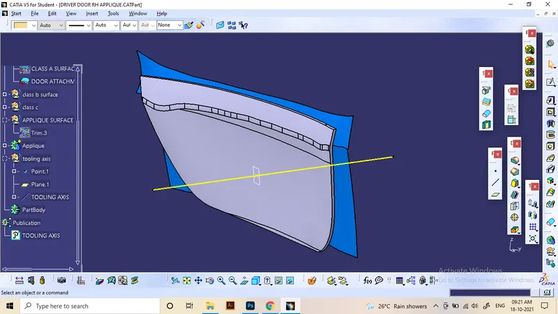
Draft anlysis:
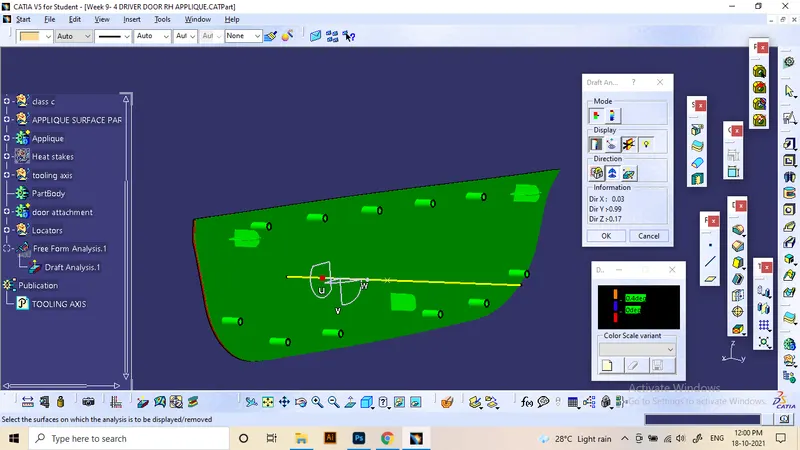
here is the result of draft analysis in the direction of tooling axis showing the surface draft angles check.
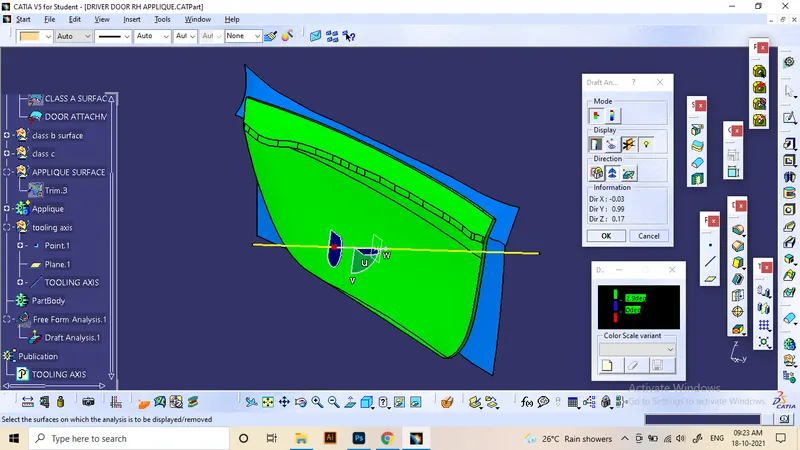
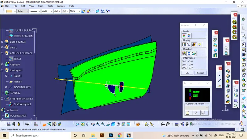
Class A and C surfaces are applicable for manufacture.
Design of locators:
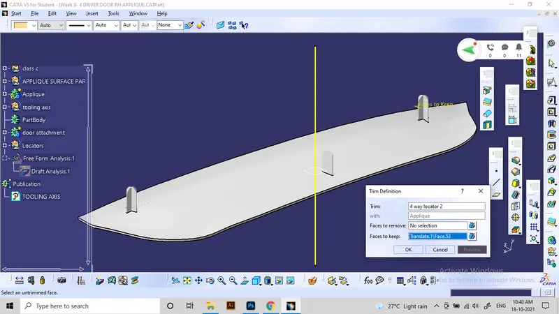
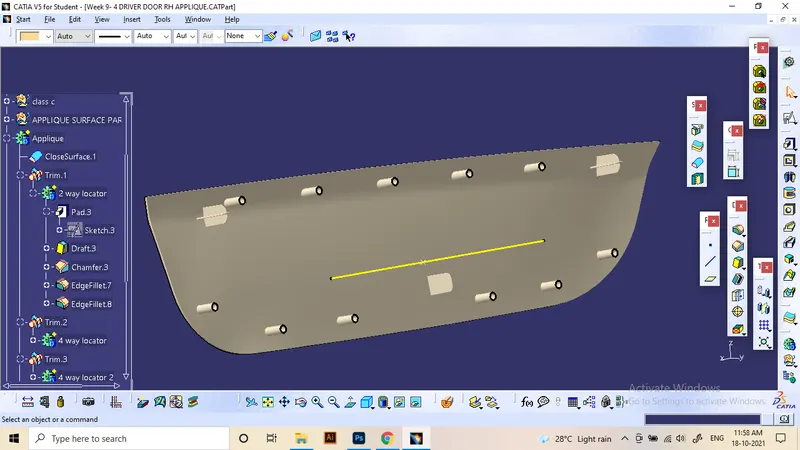
According to the 3-2-1 principle, we have to construct 3 locators for the fixing of this component on the class B side. It includes 2 number of 4-way locators at each end sides and a 2 way locator at the middle lower portion.
Each locators arrest different degrees of freedom. So these can position the applique rigidly to the attachment part of door trim.
Cross section of a 4-way locator is in a '+' shape and 2 way locator is a form of a vertocal line. Constructional features are shown below:
Thickness is given and 1.3 mm.
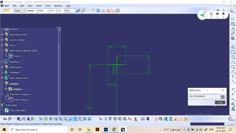
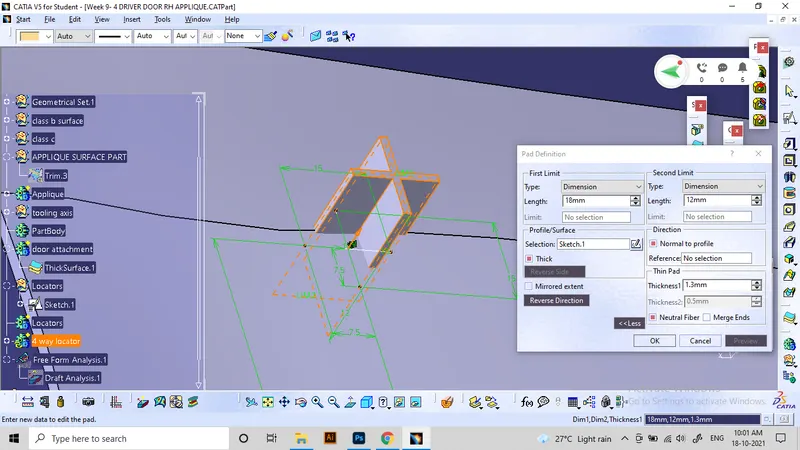
All objects and projections must be drafted for 0.5 degrees.
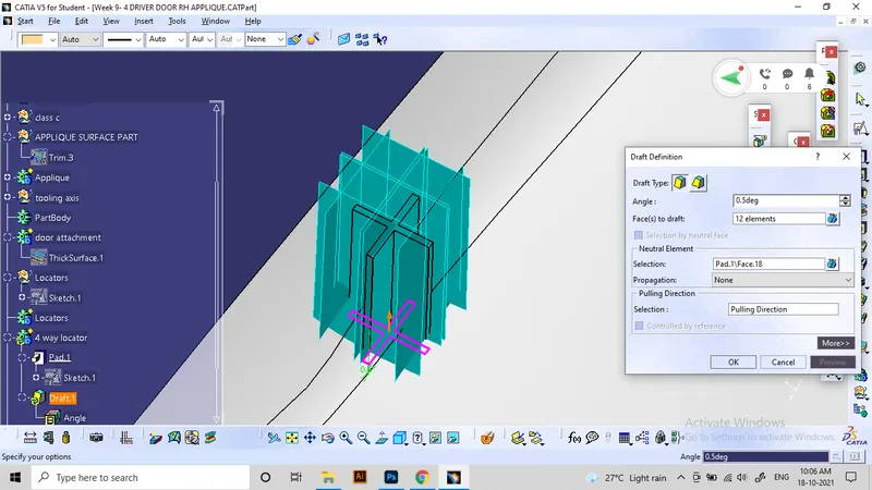
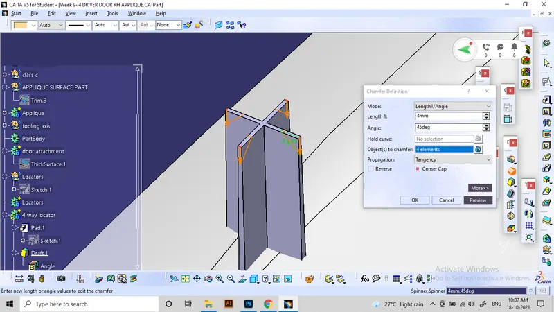
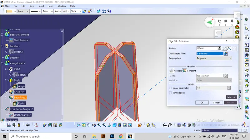
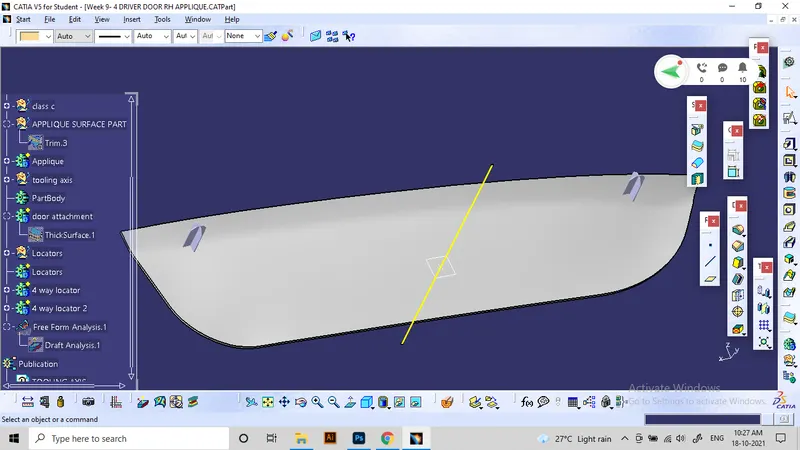
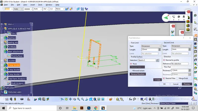
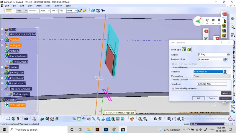
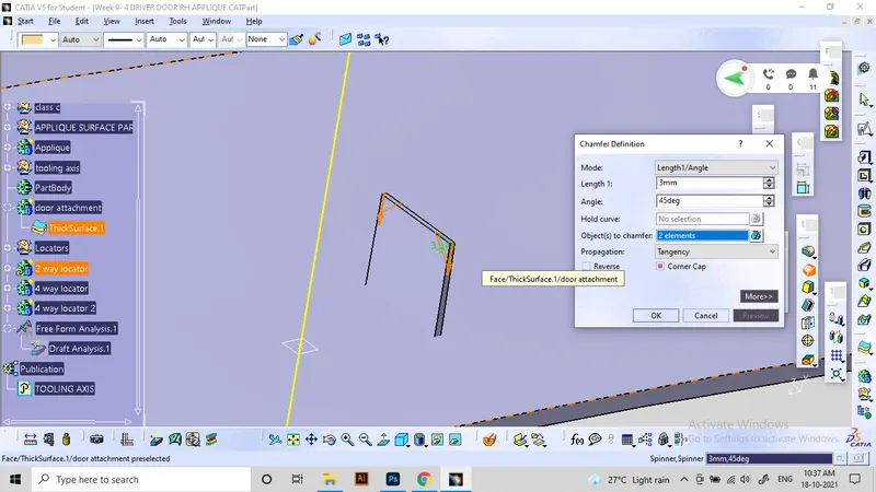
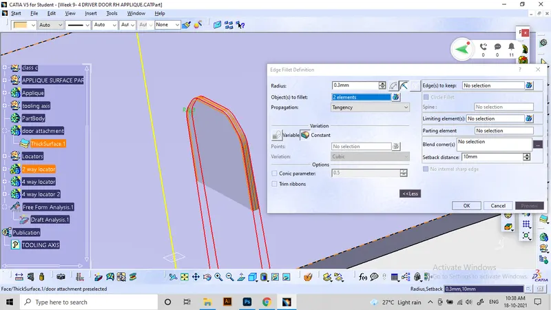
Locator parts are them union trimmed with solid model to make it into single object.
Heat stakes projections:
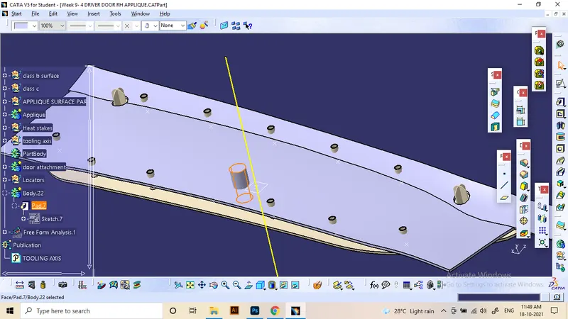
Projections required for heat stakes are in the form of a hollow cylinder. These will be used later for heating and melting to join with attachment part. Depending on the part and type of tools used for this process, multiple projetions are required spaced a common distance.
For constructing heat stakes, we need to make reference points spaced at equal distance around the class b part. It is possible by taking offset curves as references from the edge curves.
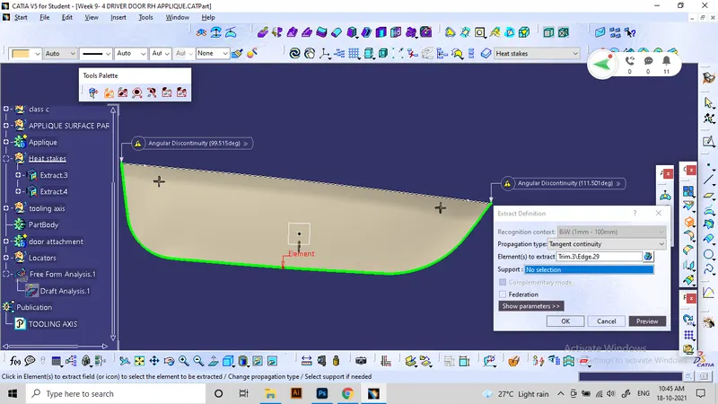
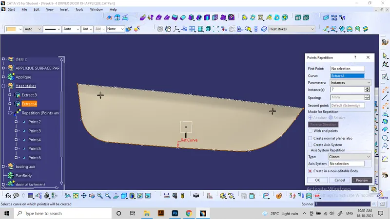
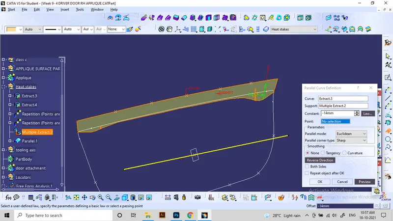
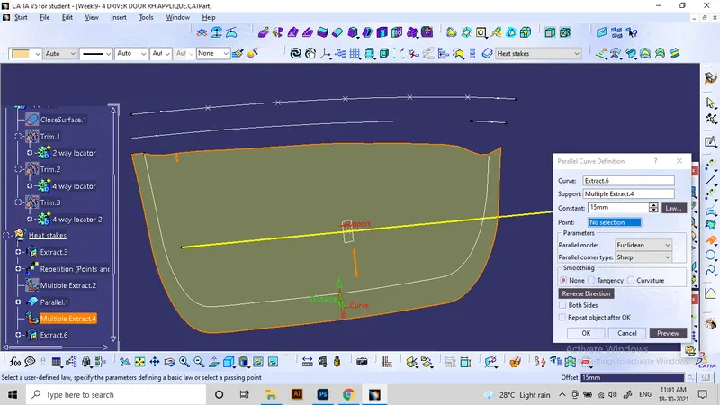
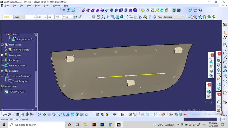
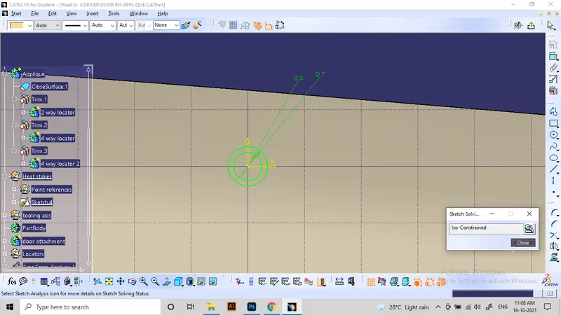
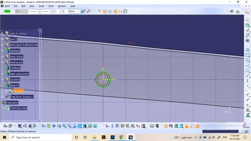
Use sketch to specify the dimeters of a single heat stake. Here i use 5mm internally, 7mm externally.
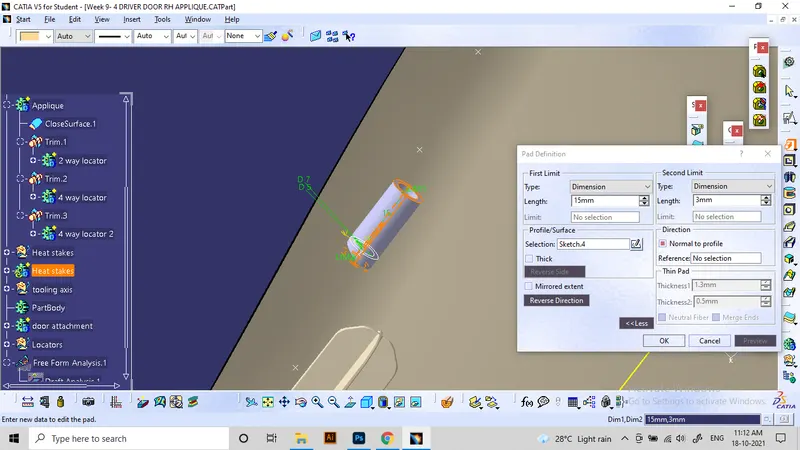
Pad this segment to make projection.
All elements needs to draft at 0.5 degree to the tooling axis direction.
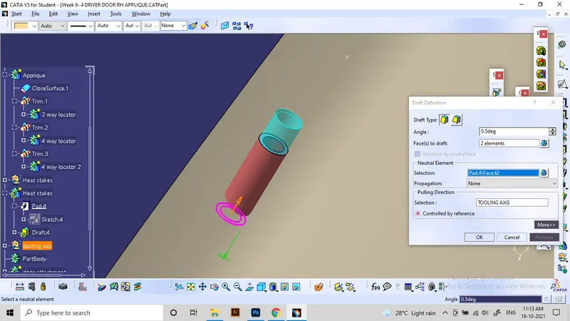
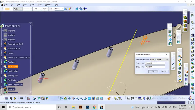
Copy and paste these segments and use translate option to align these to all points.
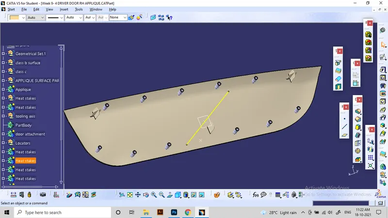
Adding heat stakes to applique by union trim. No projections must be visible at the class A surface.
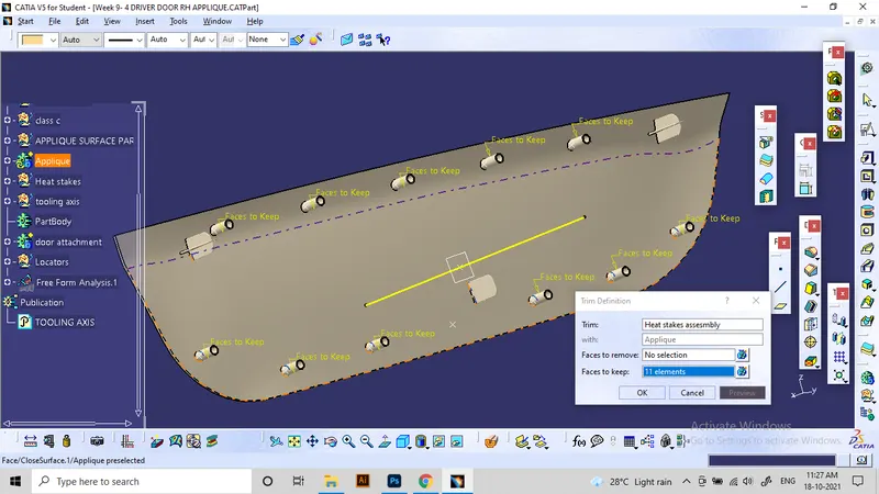
Door attachment part details:
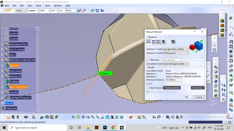
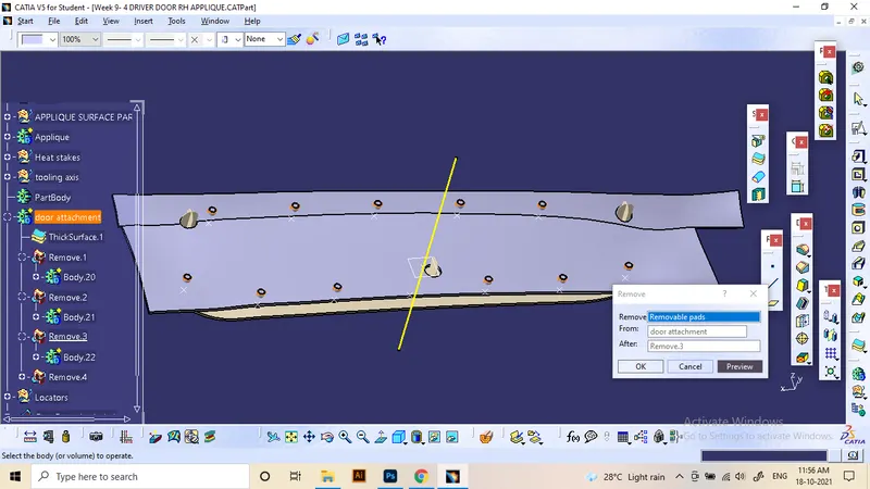
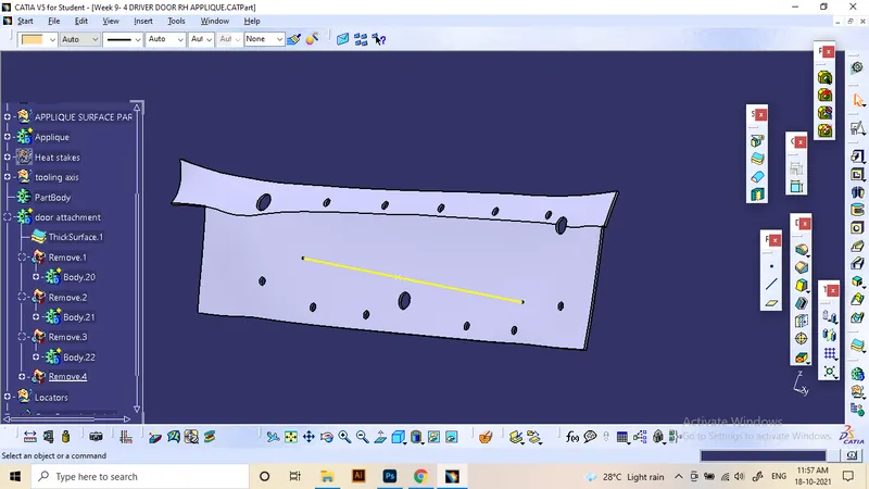
In order to fix these locators in position, proper holes have to be provided on the attachment surface. Use previous sketches to find center points of holes and pad them. Then the pads can be directly removed from the attachment part. Hole gap to locator pins have to be kept minimal.
Final Draft analysis- Results:
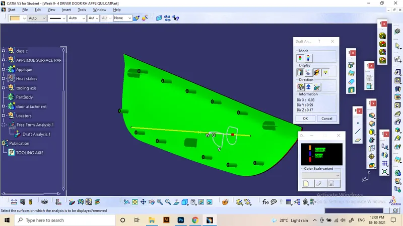
This is the result of draft analysis for class B side. All projections are drafted at 0.5 degrees.
Conclusion: The process of heat staking has been studied and implemented in the design of an interior component. Learned how the alignment and locators work for an attachment feature. This design will help to identify and generate proper assemblies in the future for plastic components.