Challenge 6 : Concept Modeling of Side Fender
Concept Modeling of Side Fender and hood
Objective: To model the given parts of a car using reference images.
Introduction: Proper flows of surfaces are an essential part of class a surfaces. In this exercise, I'm trying to develop 2 main components of vehicles, which are Side fender and hood.
Design methodology/approach
Setting up the workspace
↓
Importing canvas images
↓
Curve structure generation
↓
Surface formation with continuities
↓
Analyzing the model by visualization
↓
Finishing the work
Assignment 1 : side fender
I will be trying to generate a model of a side fender from the given single canvas image.
As usual, the modeling starts from a basic curve structure. Then the required surfaces will be created as positional or G2 curvature continuity as per the design given.
First setup the workspace on an orthographic view and import the canvas image to the workspace. it will be assigned as a reference in a layer and then the opacity will be reduced using marking menus> plane editor.
then start tracing the edges of the outer portion which is a basic flat curved region as we can see from the reference.
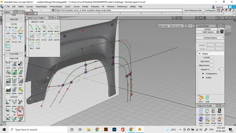
Then fill the region using square command. for the adjacent surfaces, we will be using a curve structyre as shown in figure, where the curves connecting the lines are a bit manipulated to form the crowns of the surface. This will help the model to get the required patches as seen in canvas.
This is the flow of surface i'm able to achieve.
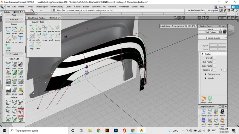
Then we move to build the sloped region of the fender. i use Msdraft for this. it helps to get an extruded plane from edges of patches at required angle and length. One surface we will make with ms draft and then the patches at it's near, will be created using rail. Those regions will be later trimmed.
For the upper region, we will use the method of intersection. That is, A crowned plane region or surface will be made using the usual curve generation method, and we will make that surface to be intersected with the slanted side. Later use intersect tool to make cos at the intersecting areas and then trim the unwanted region to make a proper form of surface.
For the patches at the right side, i'm extruding a surface which later to be trimmed as per the reference. As you an see here, the flow is normal and the edges are made in proper alignment.
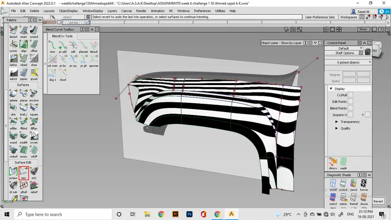
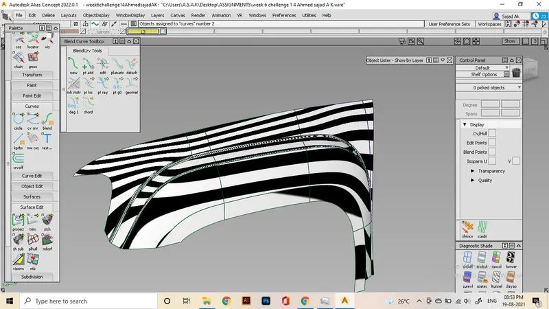
Now use srfillet tool to smoothen the edges of the patch. Use chord setting and G2 curvature for ensuring proper flow. And then for the alignment of edges we use various methods like trimming, and intersecting, maybe suing the square command as required.
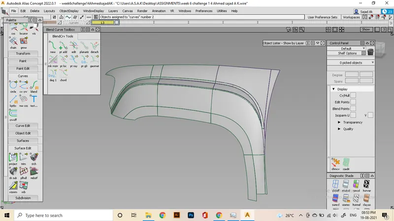
After cleaning out the surface and trimming exessive areas I achieved this result.
Assignment 2: Hood
For this project, it is actually a concept model. The reference i use is not an orthographic image so, the Accuracy of the model will be limited since i'm assuming the overall dimensions.
Making hood part is somewhat a simpler than that of fender, since it have less areas to take care of. Resulting in a better structure.
Method used is general that include all the Curve structures and curvature alignment. Since the hood mostly include flat region, i will build the flat parts first and later align the Curves as G2 to the edges of the flat part for reducing distortions.
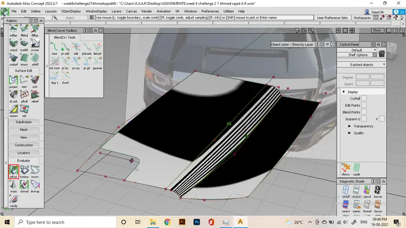
This is the main surface of hood, were i ensured G2 curvature for the joining edge.
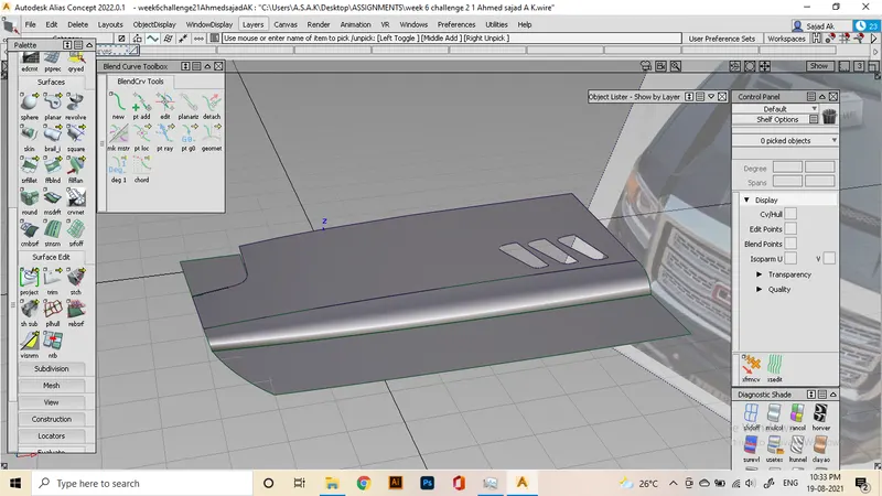
As you can see,The flow is normal. And i added the necessary details on the top part also.
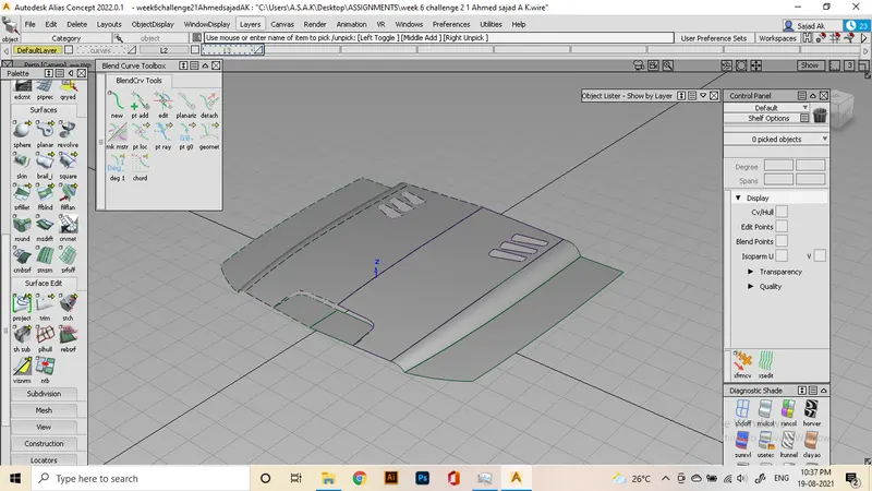
Since this is a symmetrical region, we use symmetry to project the other half of model.
Conclusion
Learned concept modelling basics for fast workflow, and understood how to analyse the structure of surfaces normally used to build complex parts of vehicles or other objects.