Challenge 7 : Concept Modelling of Steering Wheel
Concept Modelling of Steering Wheel
Objective: To study the anatomy of a steering wheel and model by reference.
Introduction :
A steering wheel is one of the complex geometrical elements in a car. It's an essential part of the interactive system between the driver and a vehicle. When looking closely at the shape of a steering wheel, we can understand that Most of the steering wheels are symmetrical elements. every single wheel is made up of the same principal elements that include, a wheel, horn, and switches. The shape of a steering wheel is constructed based on the ergonomics of the driver and they must reflect the overall design language of the interior of the car.
Design methodology/approach
Setting up the workspace
↓
Importing canvas images
↓
Curve structure generation
↓
Surface formation with continuities
↓
Analyzing the model by visualization
↓
Finishing the work
Description
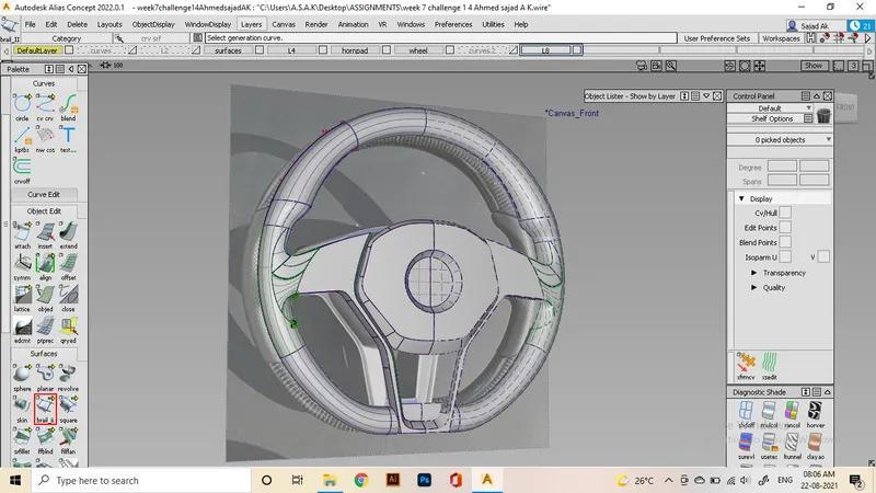
In this project, I'm creating a steering wheel of a mercedes benz AMG car. As you can see from the reference, It constitutes of Symmetrical elements with all basic parts. The structure is made up of 3 basic parts. The wheel, horn, and a metallic component that hold the horn pad and the control switches.
We will be making all three elements using the same methods studied in previous projects. Only the difference is in making the wheel of steering. For that, we will use curve generation using the rail command. first, I make a circle as the diameter of the full wheel and revolve another circle over it to make the wheel. Since the bottom part of the wheel is a bit straight, and there are some detailed areas in the middle portion, we divide the wheel into multiple sections.
Let's make the simple and basic element, which is the horn pad. we only make half of them. Start by tracing the shape of the horn with curves and then project it on a plane and trim to make the necessary part. after that, we use msdraft to make curved regions to the back and connect them using the freeform blend. in order to achieve positional and G2 curvature regions, this method will help. then i will use intersections and trimming to complete the horn process.
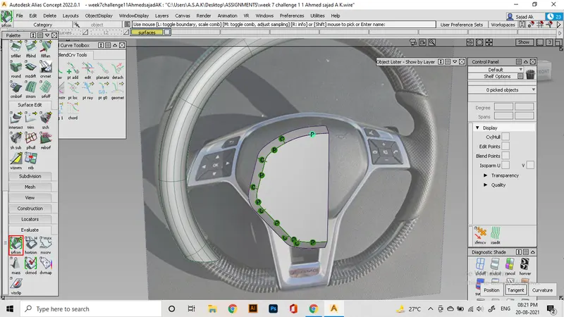
Next move on to the metallic structure. As far I understood from the reference, this part has a lot of slanted and plane regions. I made a plane surface behind the horn pad and start building the plane shape. Later project the curves and use trim and intersect to create that geometry.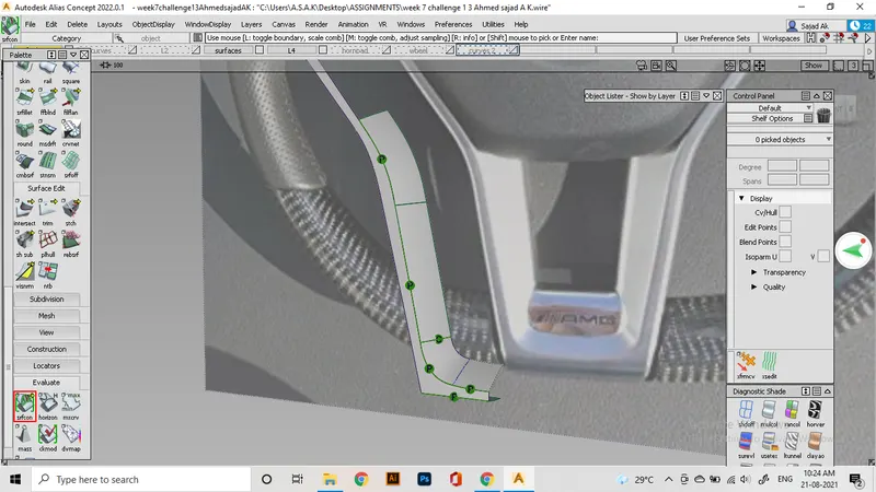
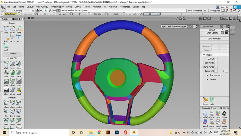
I'm able to achieve continuities as shown here,
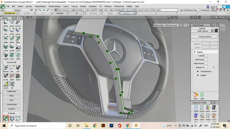
For the bottom wheel part, there needs a straight part of the wheel, For achieving this, we can make a short straight part using rail and then align it to the previously made wheel as g2.
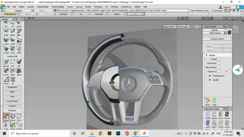
The next main part is the handle section of the wheel. Since we don't have the exact position or dimensions, we use hypothetical curves at the regions of the handle. There are a lot of difficult curve geometries. So we only make that region as good as possible using the basic forming tools.
The process starts by trimming the half section of the middle region. That portion we will align to the metallic part using the hypothetical curves. We might require a lot of curves, blends, alignments. and square, rails, ffblend, trimming, intersecting to make those regions.
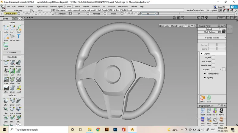
This is the best I can achieve at that portion, by this, we are analyzing the structure with evaluation tools and finishing the work.
Conclusion
By this work, I'm able to do modelling as close as the developed concept. I'm sure this level of creativity will help to do more self projects and by practising, i will be able to be a cas modeler.