Week 9 - Project 1 - Door Applique Design with Engineering Features
Week 9 - Project 1 - Door Applique Design with Engineering Features
Objective:
To create the Door Applique Plastic component using the given Class-A surface, create engineering attachments (locators, heat stakes) and to run draft analysis on the components.
Creation of tooling axis:
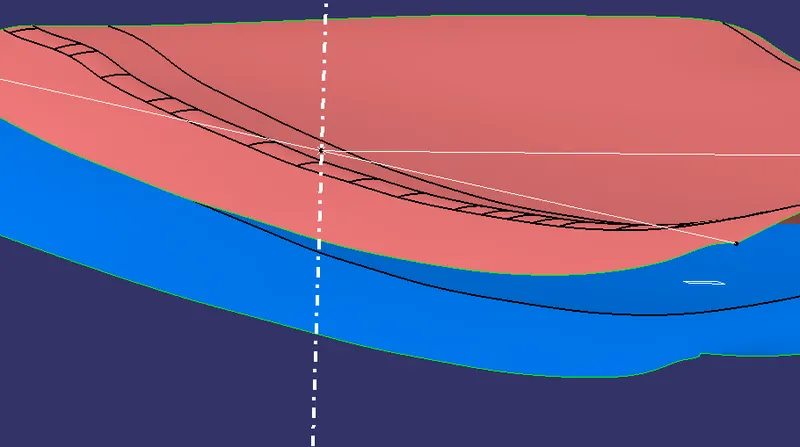
The tooling axis for this almost flat A surface which is tangent continous (G1) throughout was created simply by constructing a line normal to the plane in which the component lies.
Draft Analysis
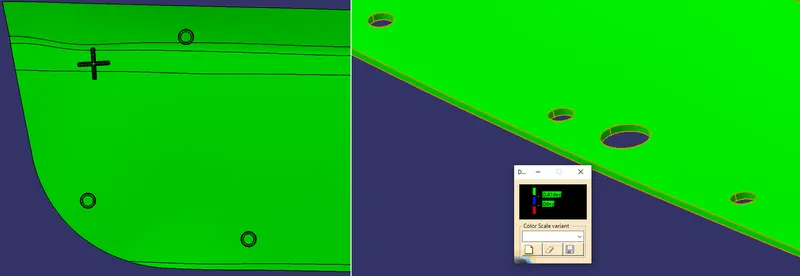
- The material mode was first selected in the view customization parameters. This setting is required for the Draft Analysis tool.
- The compass was used to create the draft direction for the component.
- The elements to be analysed were chosen and the Colour Scale displays the range of draft angles within the component. The standard maximum allowed draft angle of 3 degrees for plastic components was entered in.
- The given model passed for draft analysis.The running point option was used to check specific surfaces within the component which may seem parallel or almost parallel to the tooling axis.

Creation the Heat Stakes and the locators:
The 4-way Locators, 2-way Locators and Heat stakes were created as engineering features or attachments and they would function as the attachments or fixation features between the aesthetic Applique door surface with the door attachment surface beneath.
The Heat stakes and Locators were created by keeping the design rules in mind. Drafts were given to each attachment created.
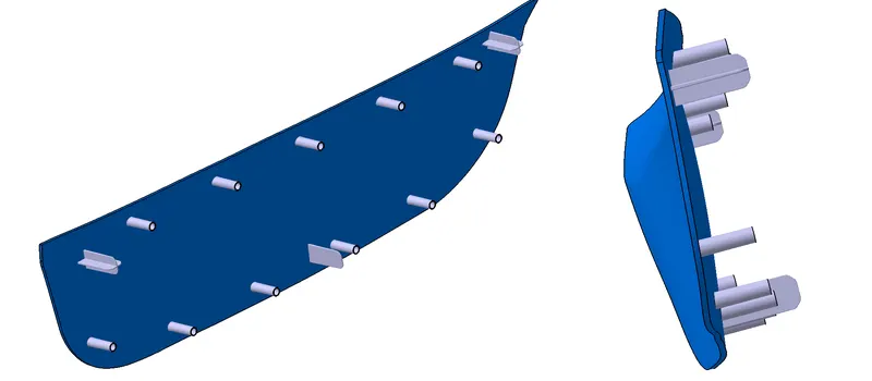
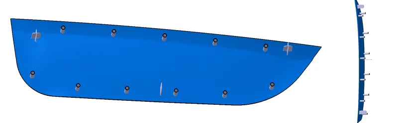
(Isometric, Front, Side, and Top View)
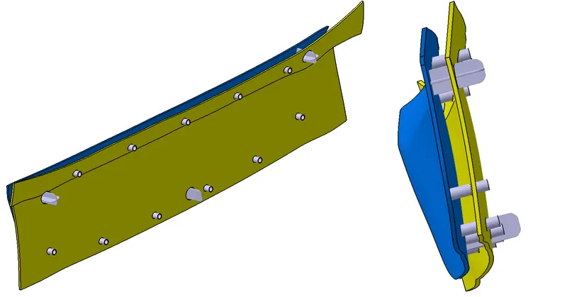
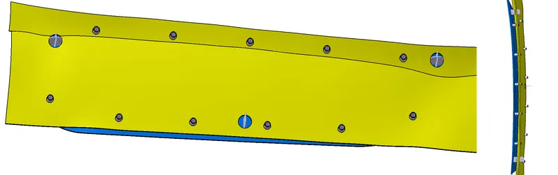
(Isometric, Front, Side, and Top View)