Project - Door Applique Design with Engineering Features
TITLE:- DESIGN OF DOOR APPLIQUE
AIM:- TO DESIGN DOOR APPLIQUE WITH ATTACHENT FEATURE
EXPLANATION:-
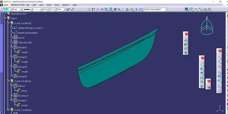
CREATION OF CLASS A SURFACE:
- Join the class A surface to fill the little gap which cannot be seen by naked eyes. Like this we get complete class A surface.
- Thicken the door attachment surface to like 2mm.
CREATION OF TOOLING AXIS:-
- As we can see that the given surface is flat and don't have some short of projection and depression.So we can simply create a normal line.
- Create a point on the class A surface.
- Create a line normal to surface passing through that point. We can use point-direction option.
CREATION OF CLASS B SURFACE:-
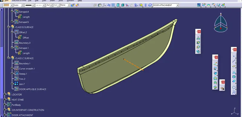
- For class B surface directly offset to thickness of component which is 2.5mm.
- Extrapolate it to 1mm so that it will be easy to trim.
CREATION OF CLASS C SURFACE:-
- Take a boundary of class A surface.
- As lot of irregulatrity where found so We used smooth curve.
- Now create sweep using smooth curve and curve and tooling axis a direction with draft of 4deg.
- Now join class A surface and class C surface and trim join with class B surface.
- Now go to part workbench and change DOOR APPLIQUE SURFACE into close body.
- Now we find that there are some area which is open and this error is coming due to class A surface
CLASS A SURFACE IMPROVMENT:-
- We find that thier are alomst 4 edge where class A and class C is not meeting.
- Extrapolate the 4 edges of class A surface to some extend.
- Now go to sweep we create for class C and extend it in another direction also.
- Now trim them out and update the join and final trim.
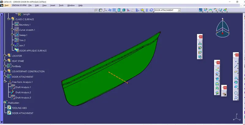
- Like this we get close body for our DOOR APPLIQUE of thickness of 2.5mm.
IMPROVED SURFACE
DRAFT ANALYSIS:-
FOR CLASS A
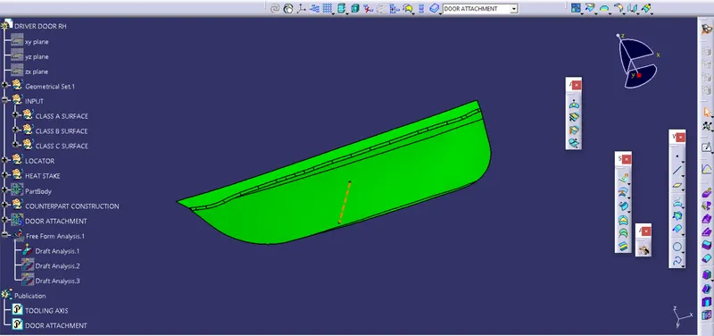
FOR COMPONENT
CREATION OF ATTACHMENT FEATURES:-
1.CREATION OF LOCATORS:-
Locator are feature that asserts the DOF of the component.Thier are two type of locator 4-way locator and 2-way locator and designed on the component using 3-2-1 principle. We will design 3 locators in which we will have two 4-way locator and one 2-way locator which asserts it movement and momentum along XX,YY,ZZ. Using these locator we have asserted 11 DOF of the component out of 12 DOF .
- Insert a new geometrical set and name it as locator.
- For any design we need sketch so we will create a sketch first for 4 way locator.
- Create a point on the surface of Door attachment and insert a plane using that point. Now create a positioned sketch using these points and plane.
- We simply create 2 line of 15mm which is perpendicular to each other.
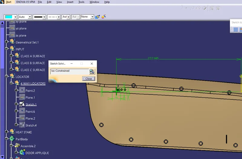
- Now go to part workbench and create pad.
- Pad should cross both attachment and door applique.
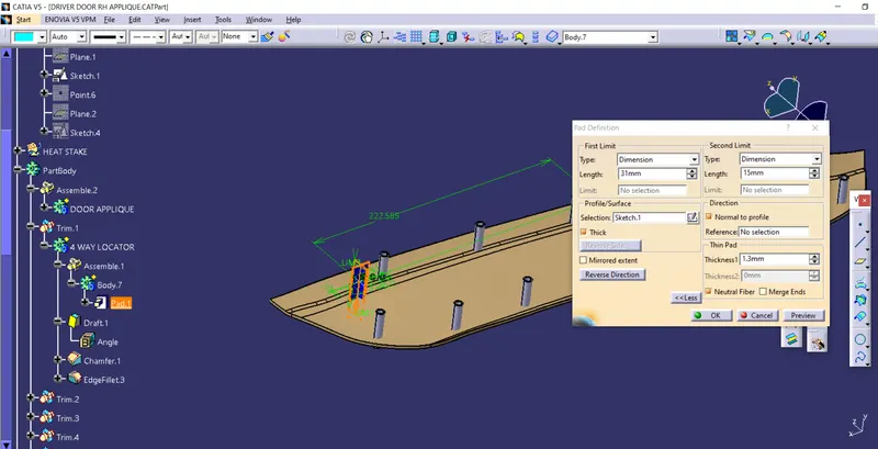
- Now give draft to the locator of 0.5deg.
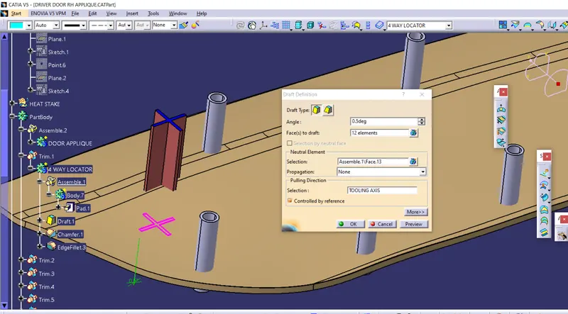
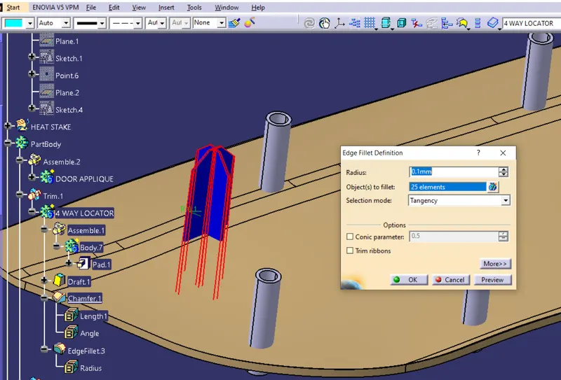
- Now add entry chamfer to top and edge fillets to all edges.
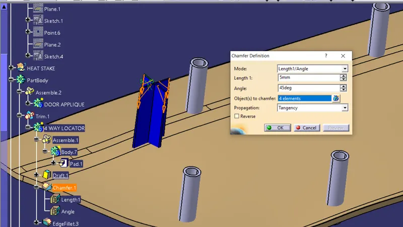
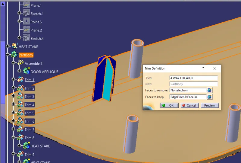
- Now we union trim the locator with main body by selecting faces to keep.
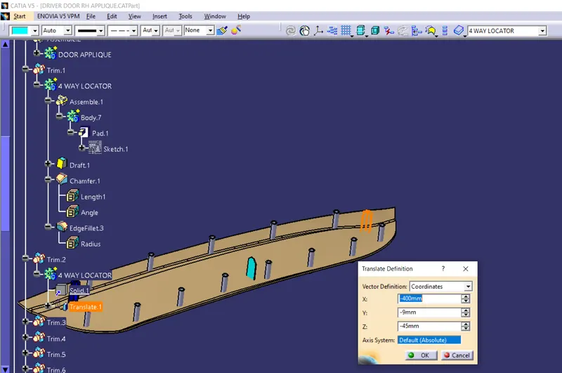
Similary we create another 4-way locator by copying and using paste special. And translate it to the new position.
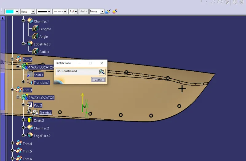
- Similarly all the process are done for 2-way locator. The only difference for this is that we draw only one line in the sketch.
2. CREATION OF HEAT STAKE:-
Heat stake are bosses which are attached to applique as well as attachment. It is using to fix the 1 DOF which has not been aserted by locators.It is fixed with attachment using plastic welding.
- Curve are extracted and shifted using parallel using.
- Create same no of points as the no of heat stake is to be created.
- We create bosses for heat stake and for that we create sketch of 2 circle of dia 7mm and 5mm.
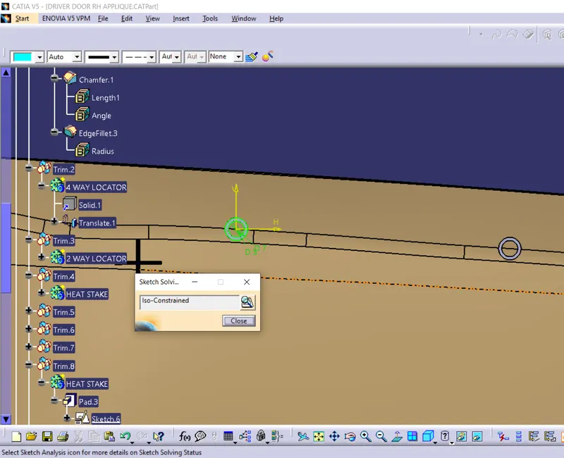
- Now we pad it. Note that It's height should not go beyond the height of locator.
- Provide a draft of 0.5deg
- Now for all other heat stakes we copy, paste special with link and translate them using points we created initally.
- Now union trim them with main body using faces to keep. Do same for all heat stakes.
CREATION OF COUNTERPART:-
Counterpart are used to locate the locators and heat stakes providing them to pass through door attachment.
- Insert new geometrical set
- We use same sketches for counterpart. copy them and paste it new geomterical set.
- Now go inside the sketch and create a circle of 15.2mm which 0.1mm clearance per side.
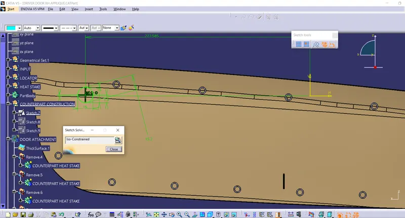
- Same we do for heat stakes with clearance of 0.2mm.
- Now pad them and provide draft to them.
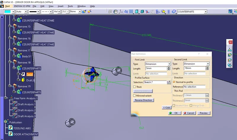
- Now remove this pad with door attachment feature.
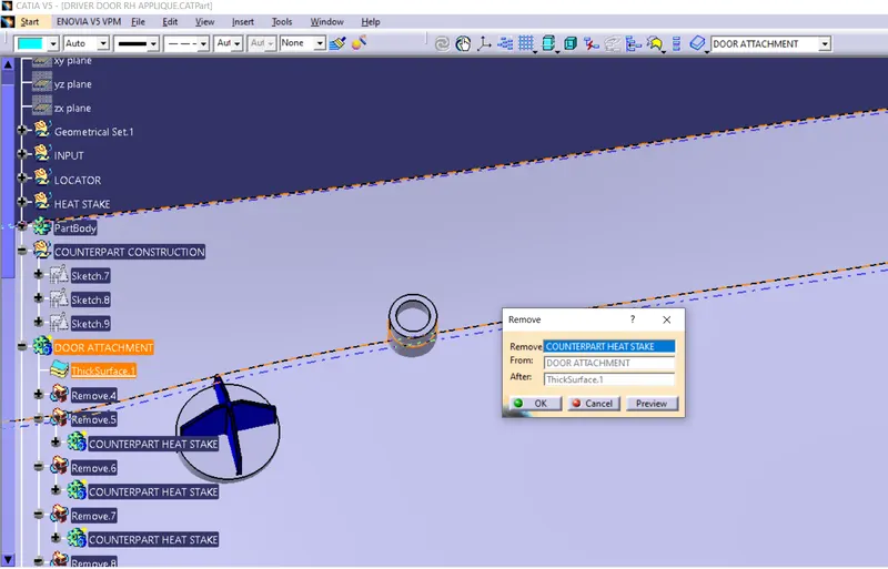
- Do same for all locators and heat stakes.
FEATURE TREE:-
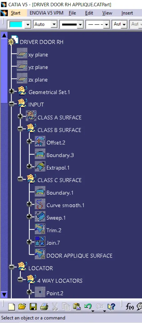
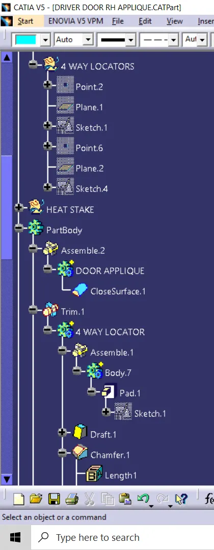
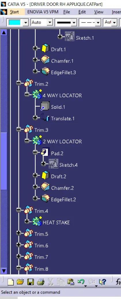
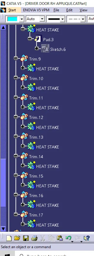
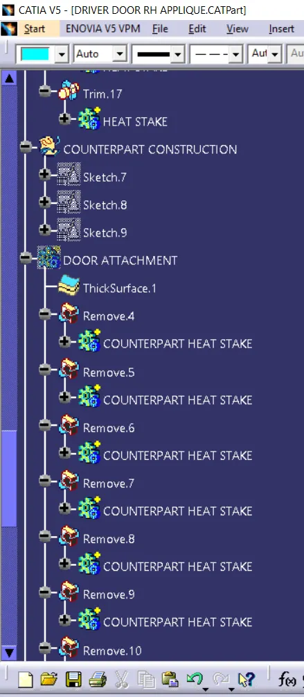
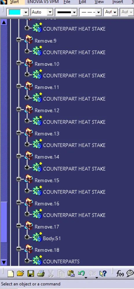
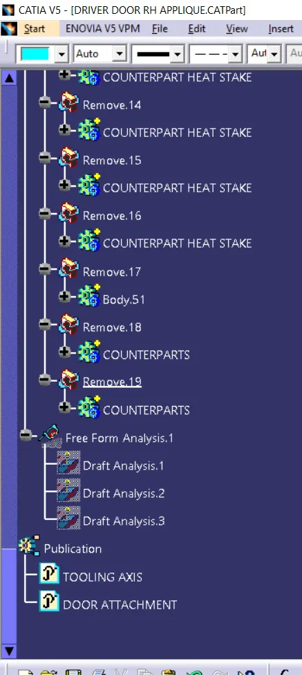
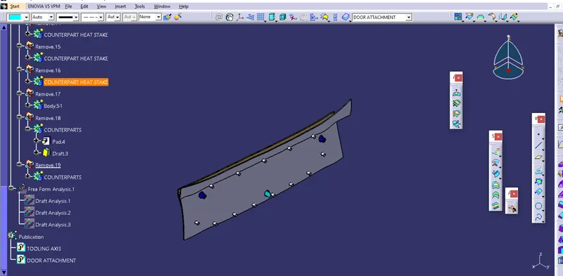
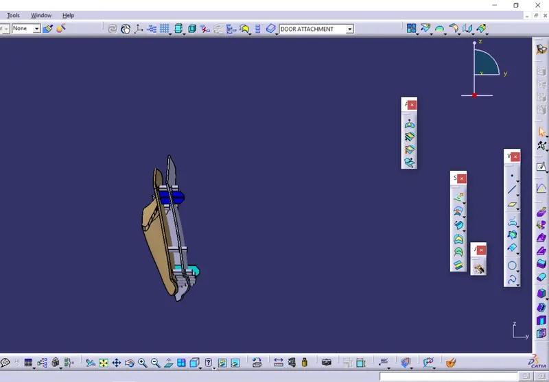
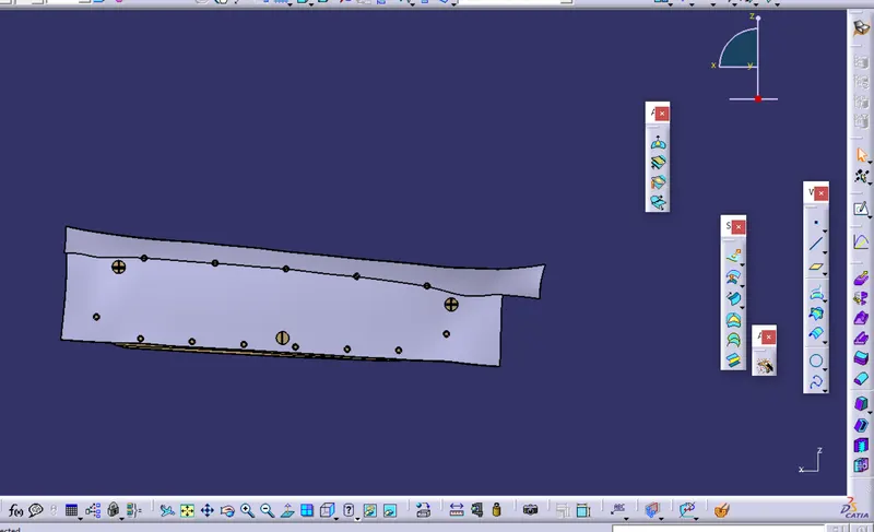
DIFFERENT ORIENTATION OF DOOR APPIQUE WITH ATTACHMENT FEATURE
THANKYOU