Week 9 - Project 1 - Door Applique Design with Engineering Features
Aim :
Create the Heat Stakes and the locators considering the design rules mentioned in the video for the door applique.
Detailed Report :
1. Creating Locators :
Inorder to fix the Door applique to the main door component, a 3-2-1 Principle is used. This principle is used to locate the job so that the job withstands the cutting forces.
Clamping of the jon has to be donr such that atleast 11 degrees of freedom of the component of locked, so that it doesnt move. In to tal there are 12 derees of freedom for a component.
2. For fixing these degrees of freedom, first we create locators
Create a plane with respect ot a point on the given door applique surfsce
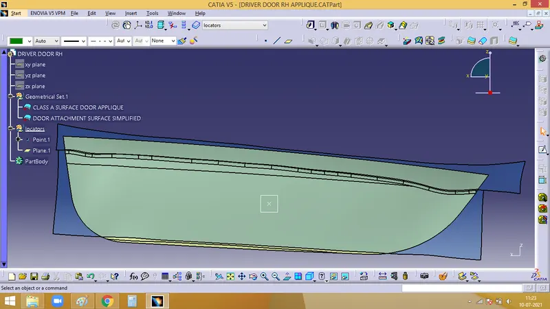
We need 3 locators for this component. Here we are goin to create a 4 way locator.
The rules are same as that of a rib, but here, it is a locator.
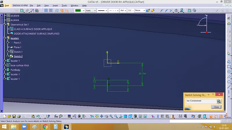
Sketch for 4 way locator
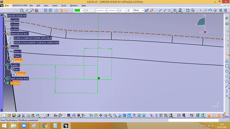
Then its padded using thick option in the Pad command.
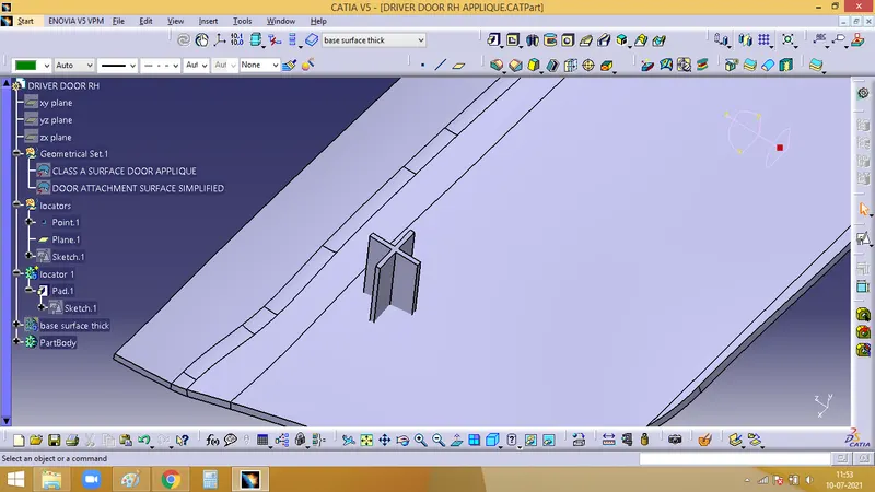
Now, we need to give draft to the locators with 0.5 deg
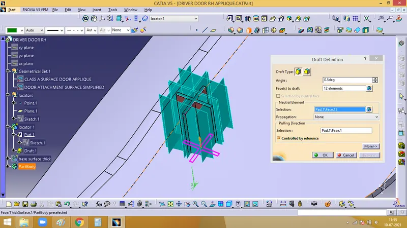
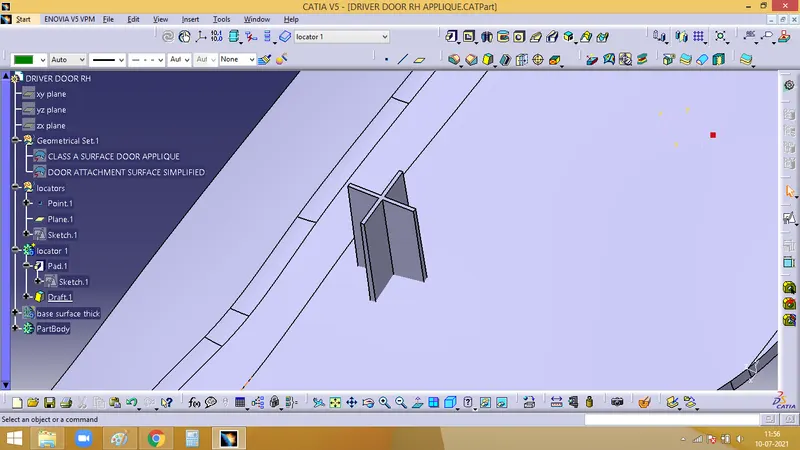
Now, entry chamfer has to be given, after which all the faces are filleted
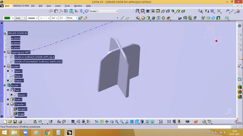
Translate this locator to a new position
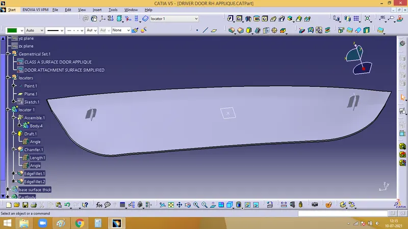
For the third locator we can create a 2 way locator, where it will arrest 2 directions.
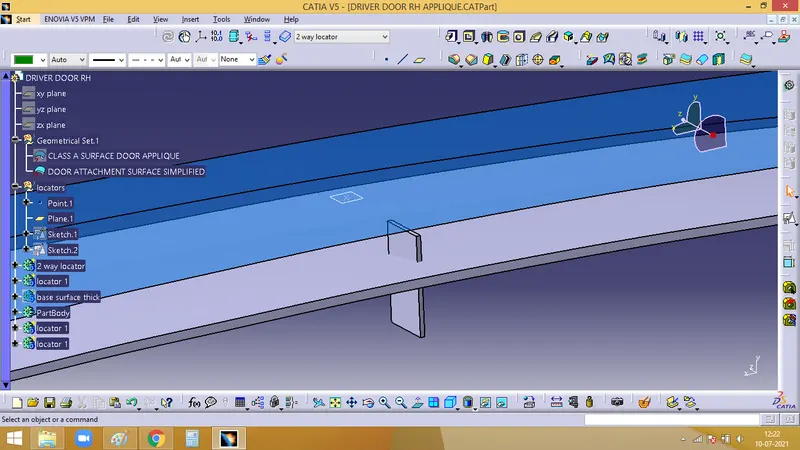
All the 3 loactors have to at equal distance from the surface
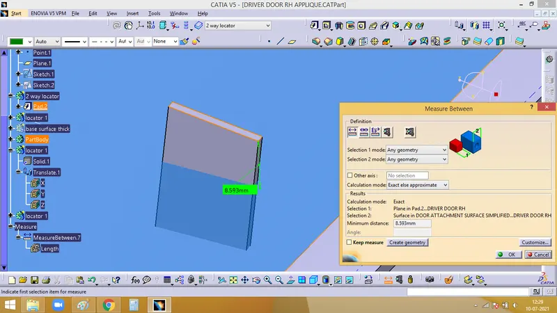
Once it is confirmed we can add the draft, chamfer and the fillet to the 2 way locator created
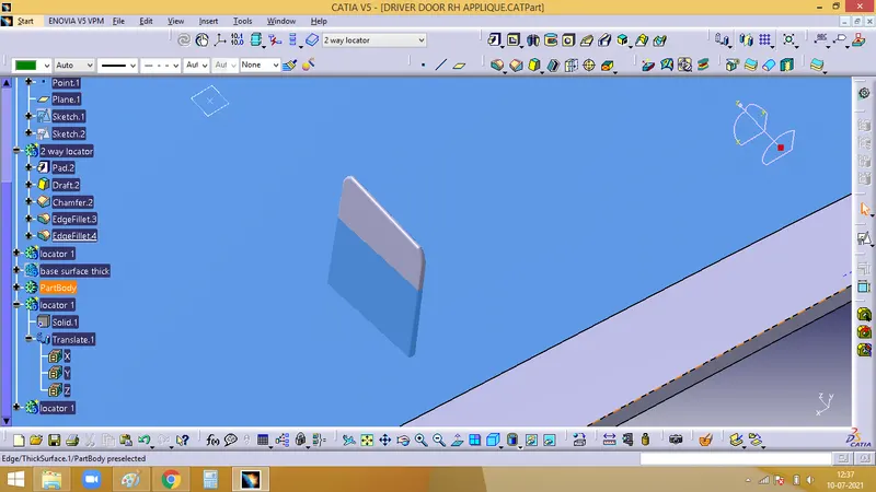
Now, we can use the Union trim the 3 locators in the Boolean operation to join it to the main body
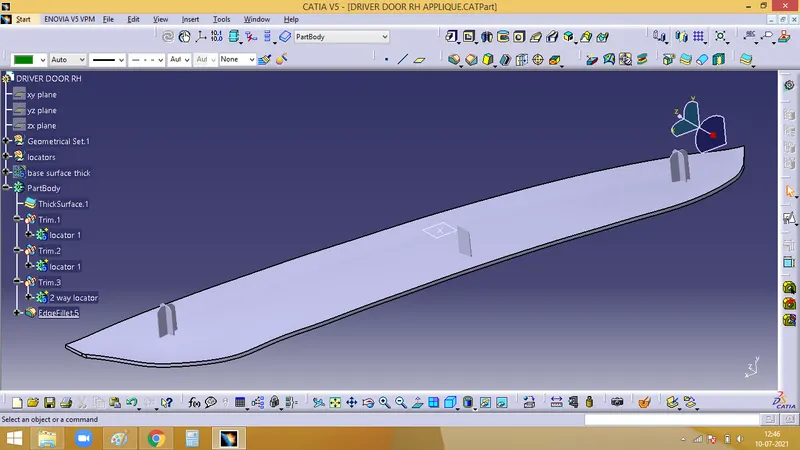
Now, we can see that the rotation along X,Y,Z axis, translation along X axis and translation along Z axis is arrested.
2. Designing Heat stakes :
Ones which are yet to be arrested are, Translation along X(+) and X(-) directions.
For this Heat stakes are to be designed.
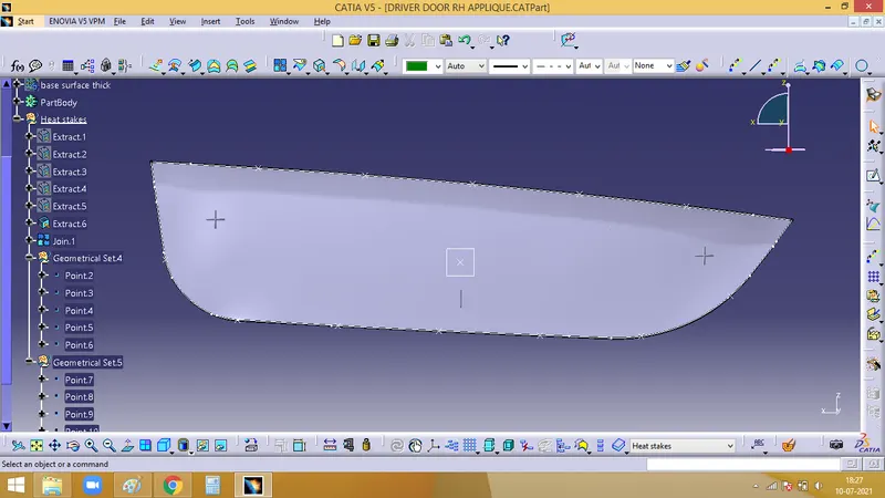
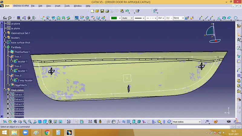
First, the boundary has to be extyracted and create points along the boundary using Points and Plane representation. These will be rough estimation for the position of heat stakes
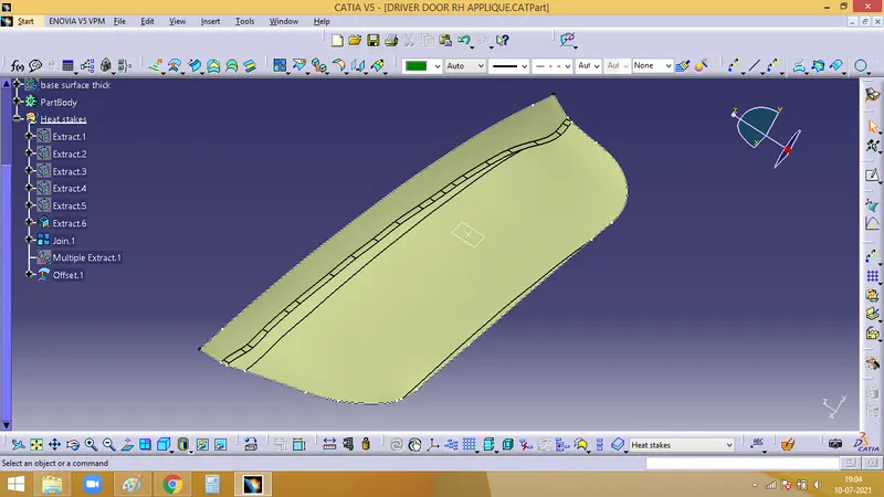
Extract the A surface using multiple extract and offset it for the value of 2.5mm
Using Parallel curve command move the boundary curves to 15mm as shown in below image
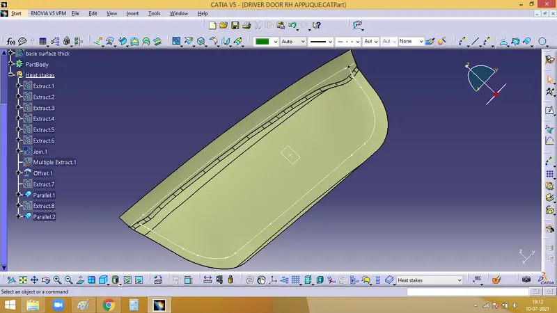
Now, we can create the position for the points, make sure that the points doesnt intersect or close to any of the ribs or locators
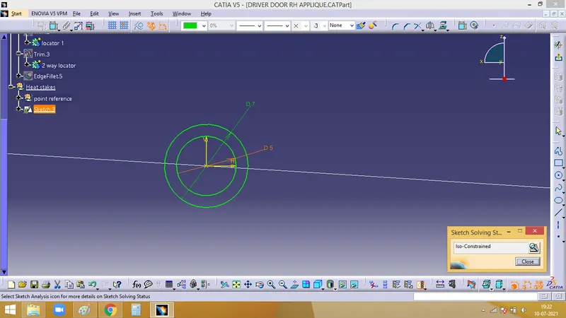
Now, we need to create a sketch for the heat stake
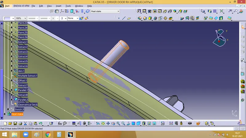
Then Pas it upto the class A surface extracted
The heat stake created, should not protrude outside the locator. As heat stakes are fixation features, it has to come after the locators. So make sure heat stake height is lesser than that of the locators
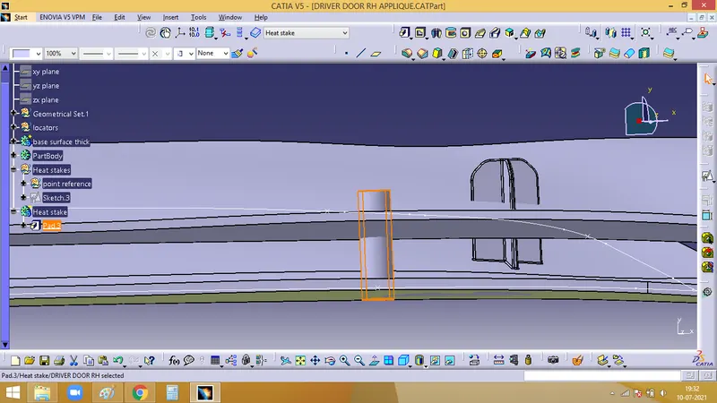
Using Translate command, translate the heat stake created to the points formed.
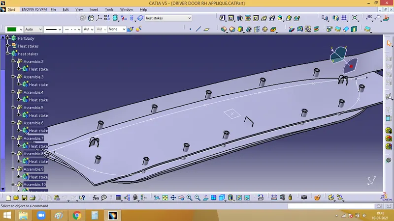
Then Union trim it with the main body and fillet at the bottom edge
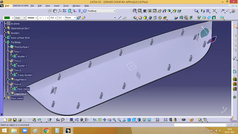
Now, we need to create clearance for the locators and heat stakes created. For which we can use the same sketch used to create locators and heat stakes
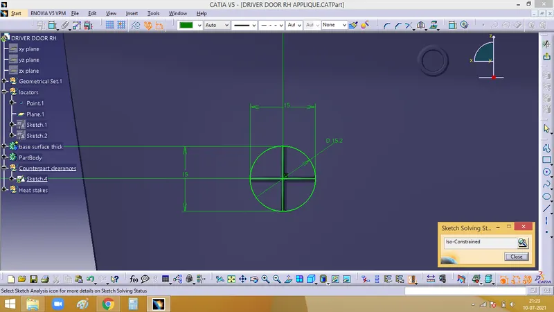
Pad the sketch and remove it from the door panel body
For the locators, 0.1mm clearance is given. Ensure the same
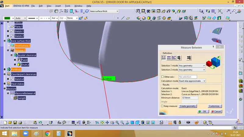
Repeat the same procedure for the other two locators as well
Now, to give clearance for the heat stakes.
For hear stake, we can have 0.5mm clearance
Create the sketch
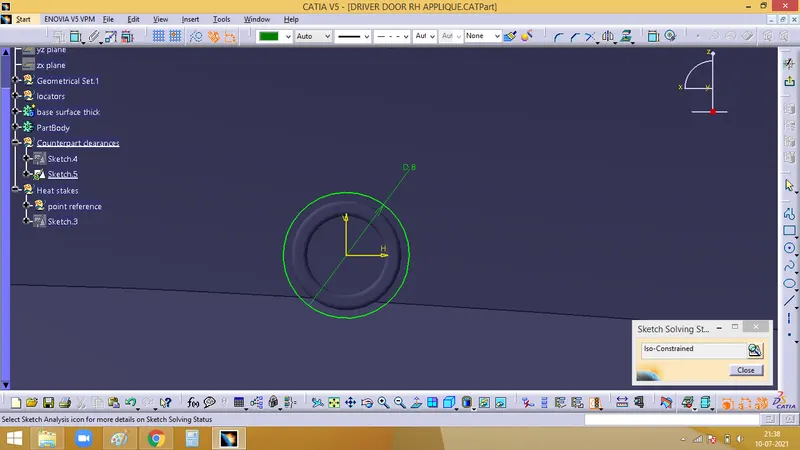
Pad it and remove it with the door panel body
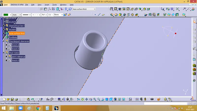
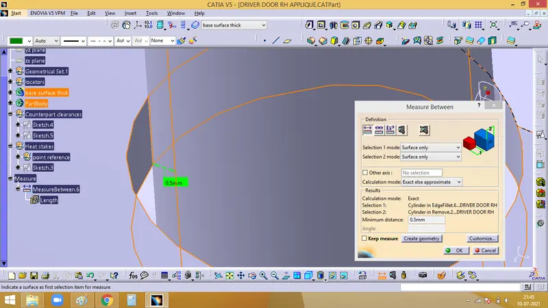
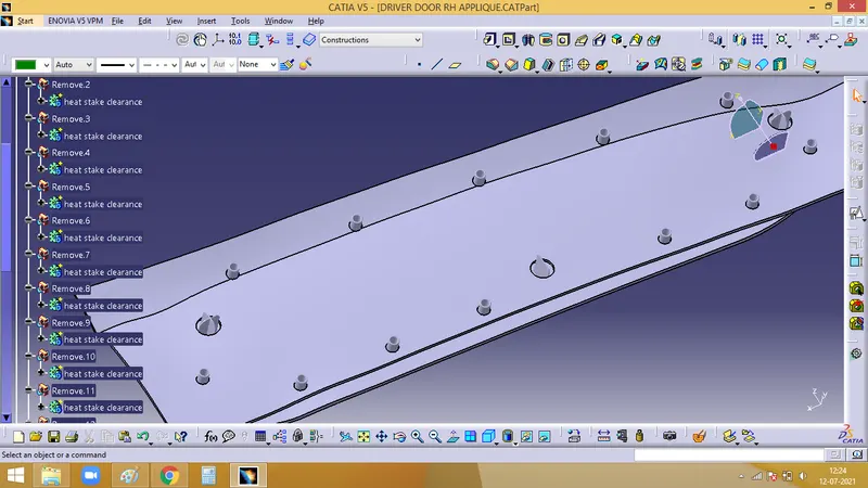
Repeat the same procedure for other heat stakes as well
3. Draft Analysis :
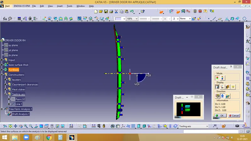
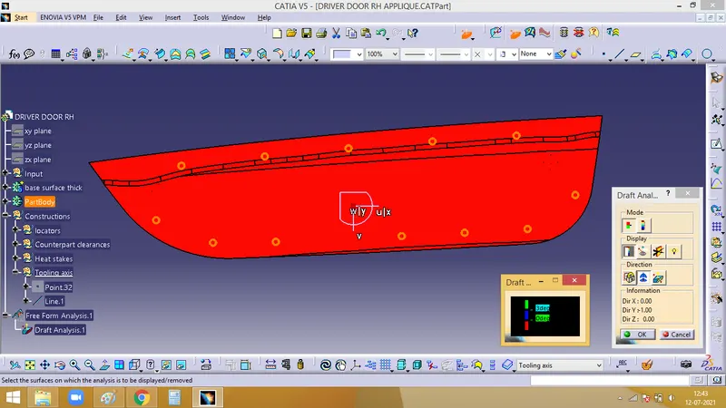
Place the compass along the tooling axis and do the draft analysisnusing the Feature draft analysis command.
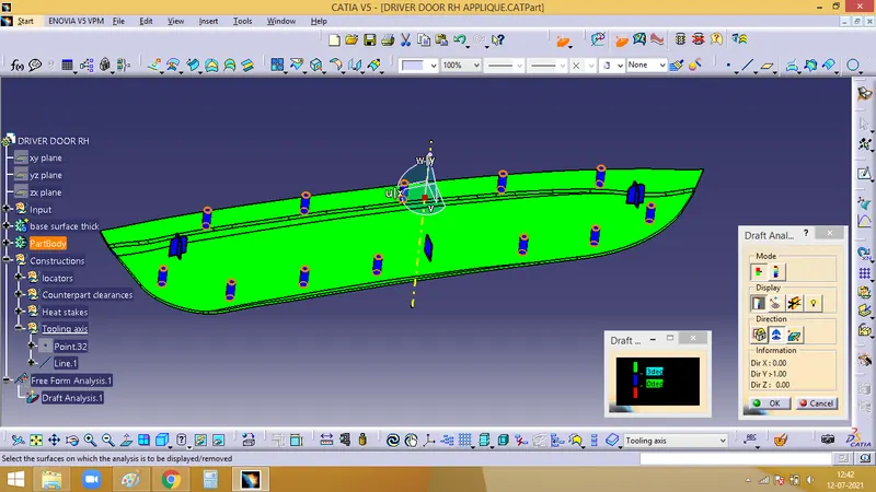
The areas in green are above 3 degress, the areas in blue are of 0 degree and the red are below 0 degess
Front view
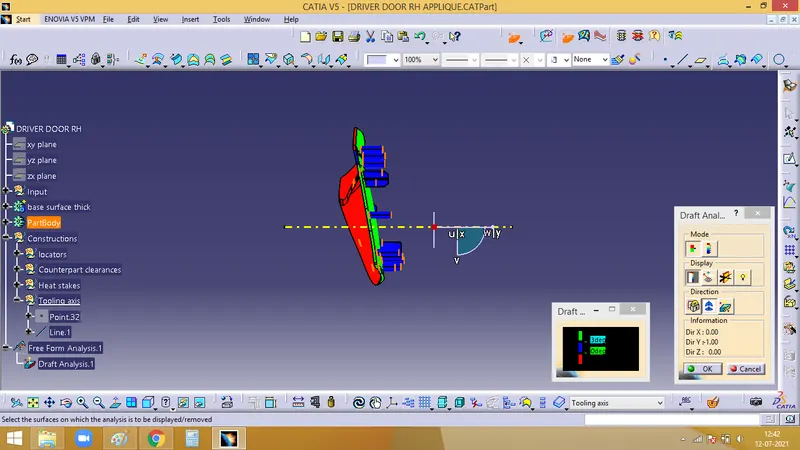
Back view
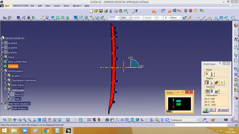
Right side view
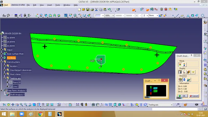
Left side view
Top view