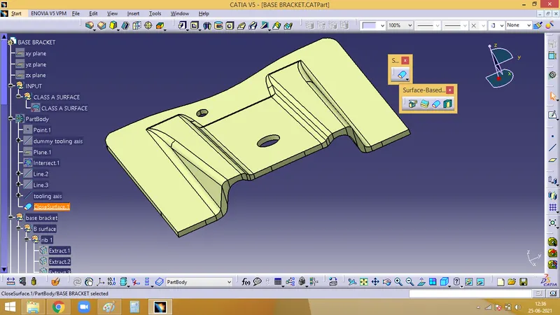
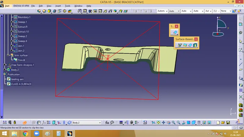
Week 8 - Challenge 2 - Base Bracket Design
Report on BASE BRACKET Plastic component design :
Aim : To create a Base Bracket component from class A surface. Starting with draft analysis of the component and further perform the class B and finally finishing the component with class C surface.
Detailed Report :
1. To check the continuity of the given class A surface. For which, the boundary icon. The green lines boundary shows that there are no gaps between any of the faces and that they are continuous.
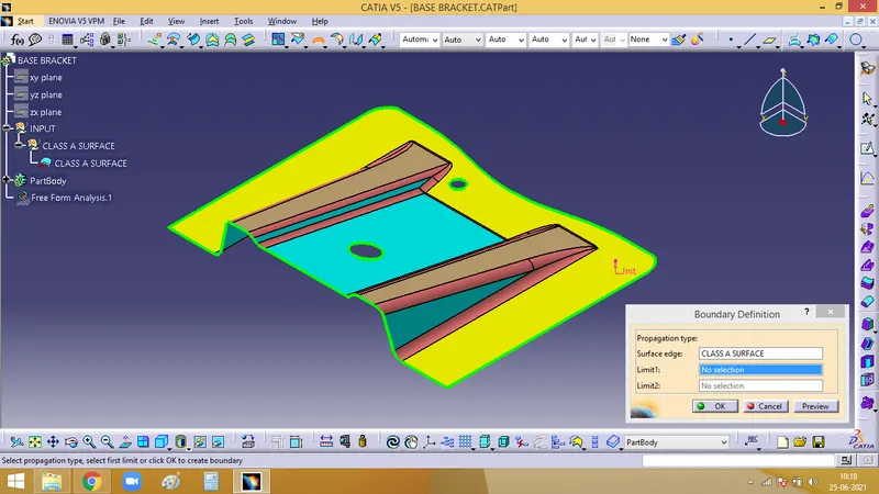
2. To create Tooling Axis direction, check for the best axis possible along which the faces of the component will clear the tooling axis. Here, for the base bracket, Z axis seems to be the best suiting axis.
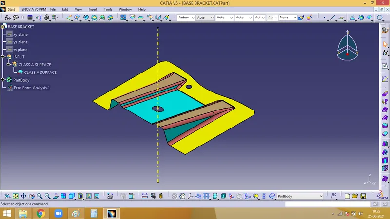
In order to clear the faces along the y axis. We create a YZ plane, take an intersection of the YZ plane with the base bracket surface.
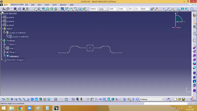
Now, we need to chek the faces which will create issue along the tooling axis. So make two lines and bisect them to make a tooling axis.
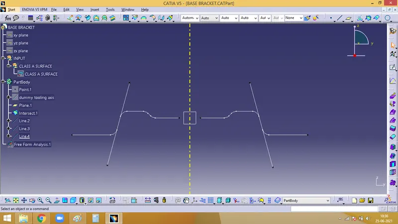
3. Draft Analysis :
Initially the material mode has to be set and open the feature draft analysis dialog box. Pick on the compass symbol and place it in line with the tooling axis.
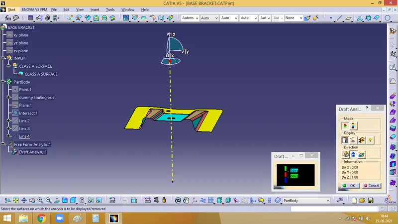
Now ahve to check for the draft. Clicj on the surface and check for the colour from the draft analysis 2 dialog box. The minimum draft needed is 3, which is checked here. If any surface is red, then it has a draft angle less than 3.
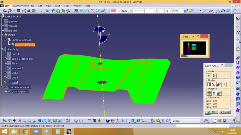
With the help of Analysis under the running point icon, we can check the draft angle of each fcae.
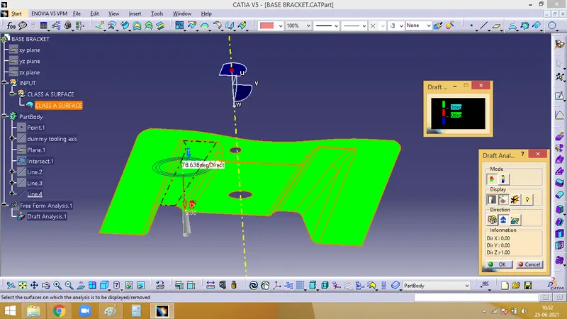
4. Crating B surface :
As fillets will create problems, it ahs ti be ignored.To avoid that we could extract the ribs and work on it separately.
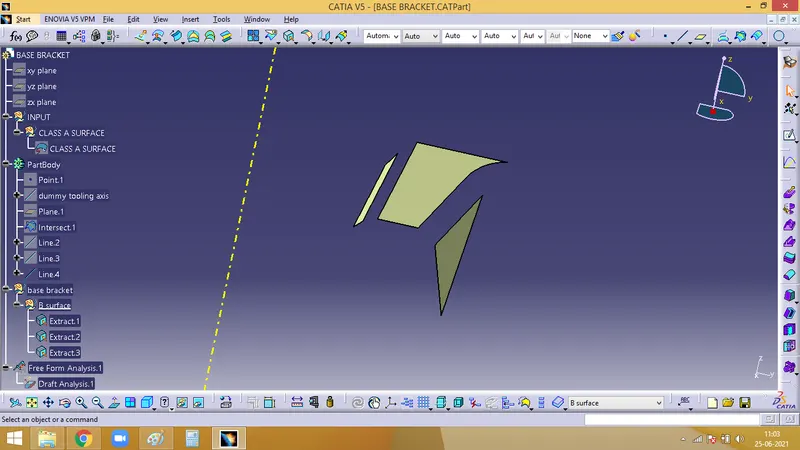
These extracted faces has to be untrimmed and extrapolated to work with it.
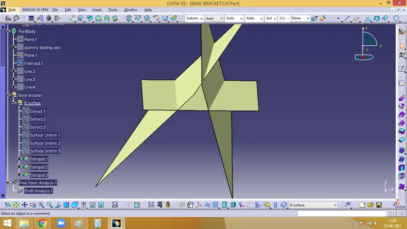
Now, it has to be trimmed to get the required faces. After trimming, it nahs nto be offseted for 2.5mm, which is the thickness of the component. Rib 1 is formed.
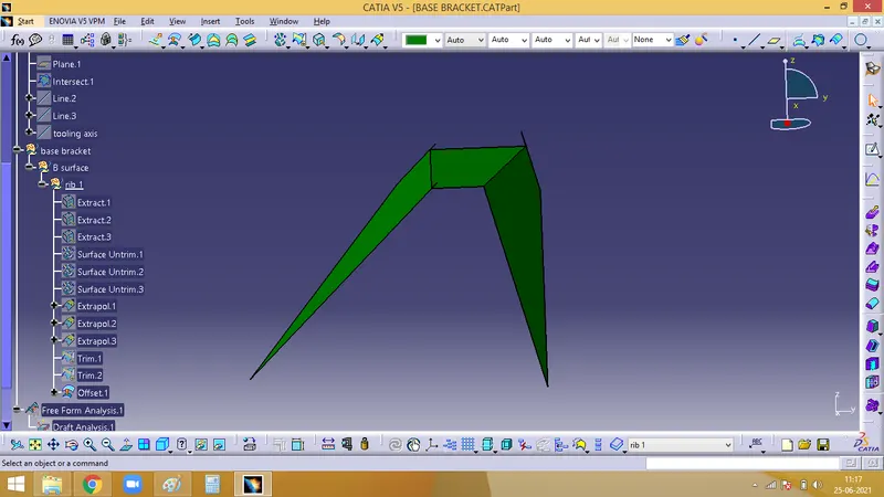
For easy selection, the Tooling axis and the Calss A surfaces are published using the PUBLICATION option under tools menu.
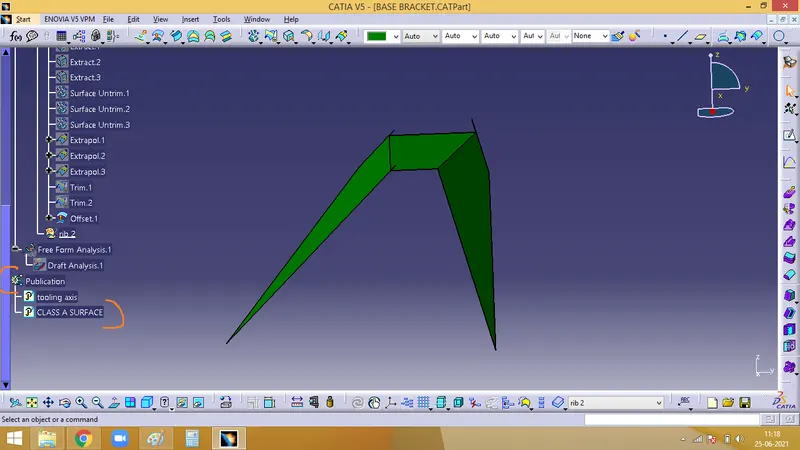
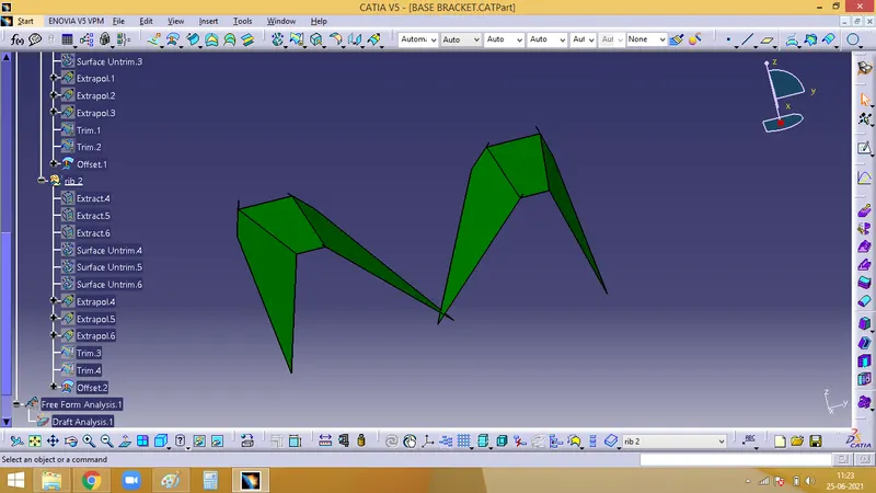
The same procedure as rib 1, has ti be repeated for rib 2.
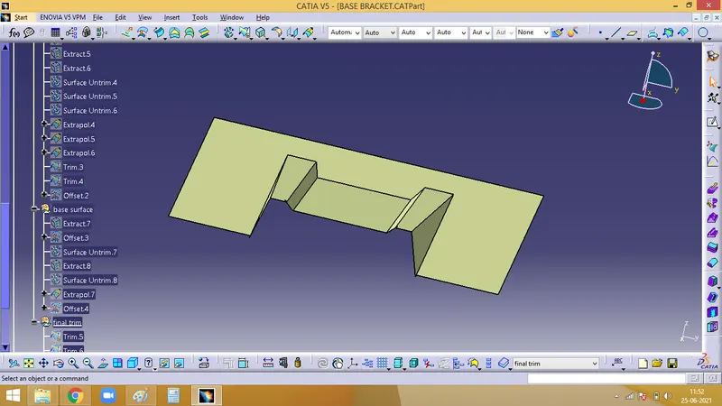
After ribs, next is to work on the base surface. Same as rib 1 and rib 2, using class A surface, we have to extract the face, offset it to 2.5mm, untrim it, extrapolate such that the faces are touching the ribs, and finally trim it and the output will be as the below image.
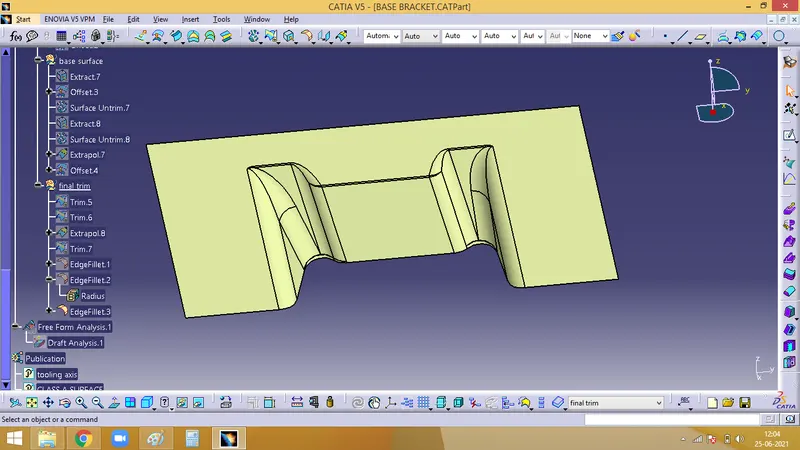
Now, the B surface crated has to be filleted and completely done.
5. Creating C surface :
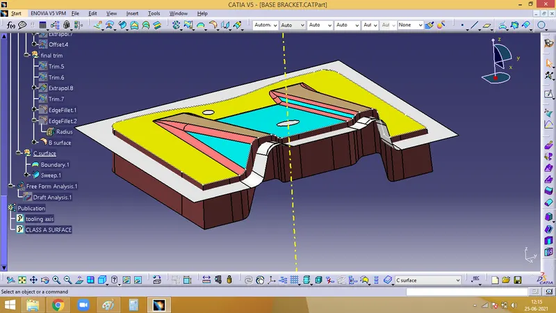
C surface is the closing surface of the A surface and B surface created along the tooling direction.
First create a boundary for the Class A surface.
We have to sweep the boundary that we created from class A surface.
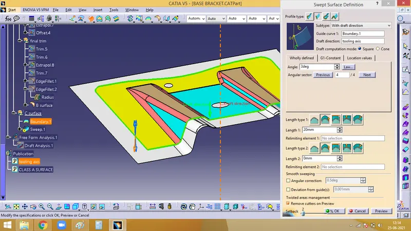
This seep formed is the C surface which will close the class A and class B.
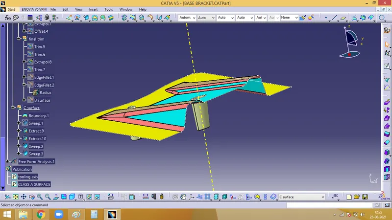
Now, we need to create the holes. For which the two holes have to be extracted. And using the sweep option, the holes ahve to be swept.
Now. join the C and A surface together
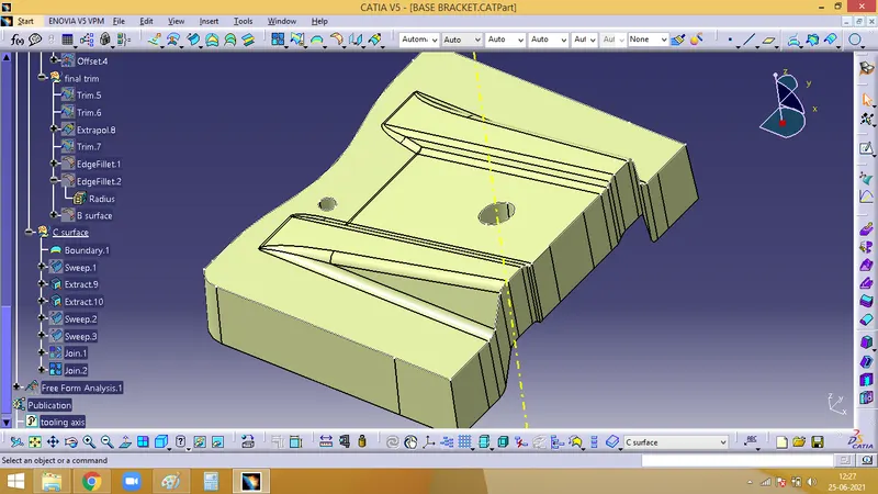
6. The final trim ahs to be done.
The final Join has to be trimmed with the B surface. After which we get the complete closed surface of the base bracket.
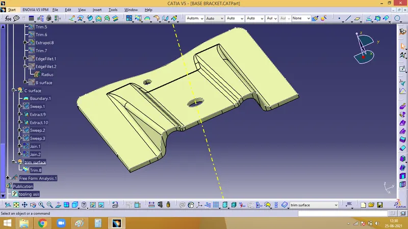
7. Final colsed surface to be turned to a solid component.
For which we need to firat define on the part body, enter into the part work bench, select the closed surface icon on the toolbar and select the final trim that we created.