Week 8 - Challenge 1 - Draft Analysis on a Fan Cover
Report on Draft analysis of Fan Cover :
Aim : To perform draft analysis for the given class A surface i.e. Fan Cover, by creating tooling axis, checking for proper draft angle and the analysis.
Report :
1. The first step is to check the continuity of the given class A surface and ensuring that there is no gap or discontinuity inbetween.
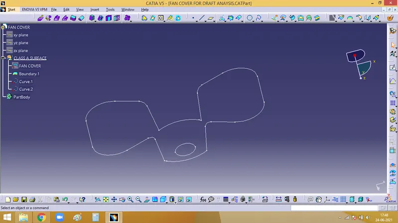
To check that, use the Boundary command, slecet the boundary of the fan cover, And the boundary for the fan over siurface is created, as shown in the below image
2. Now, a tooling axis has to be created. Tooling axis is the direction in which mold or the core and cavity opens. For this, the component has to completely clear the tooling axis in the given direction.
Visually one has to check for the possible tooling direction according to the part provided.
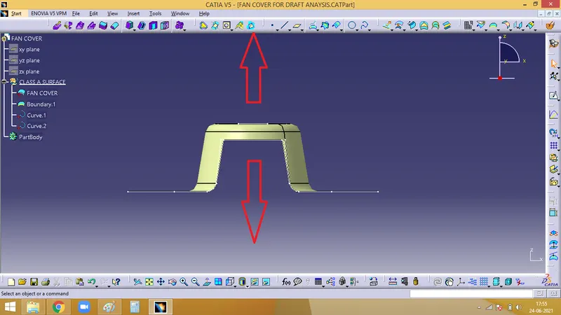
For this particular Class A surface, along z aixs, it seems better to create the tooling axis, where we can clear the hole as well as the slot.
3. To create a Tooling Axis :
Create a geometrical set for tooling axis.
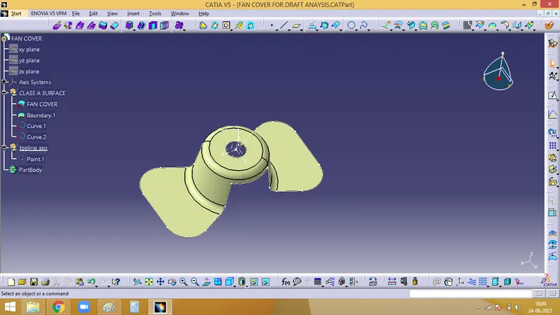
Insert an axis system at he centre as shoen in below image
Now, intersect the ZX plane wit the Fan cover surface. AS a result of which we get an intersection line.
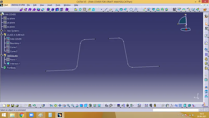
The tooling axis with respect to the intersecting lines has to be solved. For which create a dummy tooling axis and check if all the faces along the tooling axis clears.
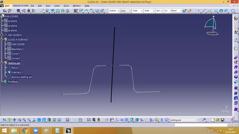
In order to avoid creating error with respect to the sketch, the particular lines can be extended
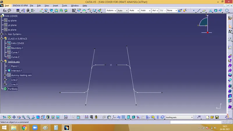
Withthese two lines, a Bisecting line has to be created.
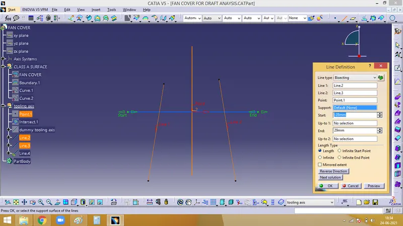
Now, the tooling clearance along x axis is done. To create similarly for Y axis, follow the same steps with YZ plane. And the result would be as below image
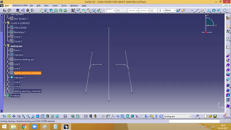
With these two tolling clearing lines alomg x and y, create a bisecting line
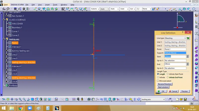
Now, we need to Publish the tooling axis formed by bisecting the x and y tooling clearance lines.
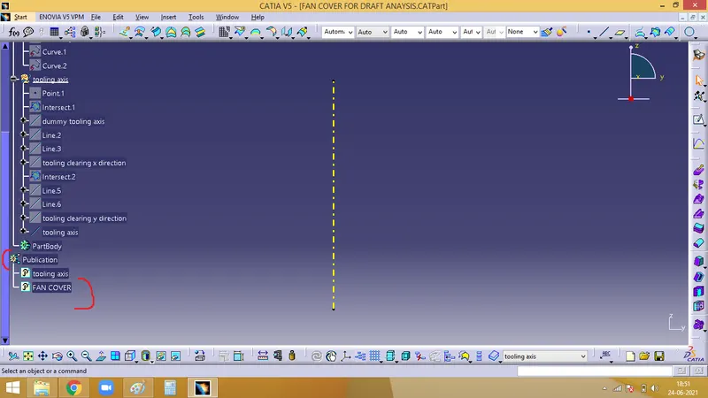
4. Draft Analysis :
Insert - Analysis - Feature Draft analysis.
In this first, use the compass to define the new current draft direction. Place the compass along the tooling axis direction. W of the compass shoulod be inline with the tooling axis.
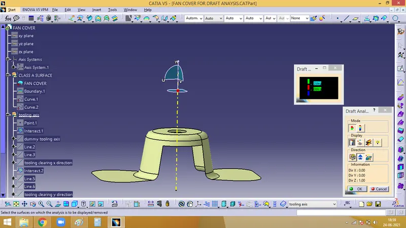
Click on the Lock incon in the dialog box, and place the cross point anywhere on the component. The component turns green.
The green represents that, according to the Draft analysis 2 dialog box, the entire component has a draft above 3 degrees. i.e. which is the minimun degree needed. If any face has draft below 3 degress, it will be represented in red colour.
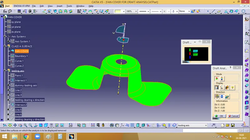
Now, we can individually measure each faces, unisng the Analysis running point icon. While moving it on the component, it will show the degree at that point.
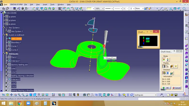
As every face is in green, it represnts that the component is clear and its ready to design.