Week 8 - Challenge 4 - Coin Holder Design
Aim :
Create the Coin Holder Plastic component through the given Class-A surface. To begin with, the tooling axis for the given Class-A Surface should be created meeting the requirements of the draft angle and at the end perform the Draft analysis on the model. Thickness of the component to be 2.5 mm
Detailed Report :
Steps followed :
1. Checking the continuity of the given Class A surface
2. Creating the Tooling Axis direction
3. Performing Draft Analysis for the given Class A surface
4. Creating Class B surface
5. Creating Class C surface
6. Final trim to join class A and class B sing the Class C surface
7. For hole
8. Creating a solid body with the closed surface formed
9. Performing Draft Analysis on the final Solid body
1. Checking the continuity of the given Class A surface
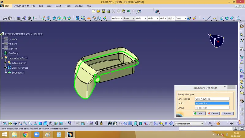
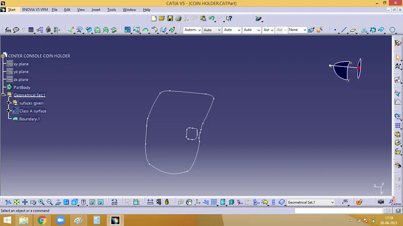
The continuity of the given Class A has to be checked inorder to ensure that there is no gap between any of the faces. It can be checked by using the Boundary command. The continuous green line represents that there is a proper continuity between the faces.
2. Creating Tooling Axis Direction
Tooling axis is the direction along which the core and cavity opens and closes. Draft angle is required for every face for smooth ejection of teh component from the core section. For this only, draft analysis is done for which primarily a tooling axis is required. In case of comlex designs more than one tooling axis might be needed for side core.
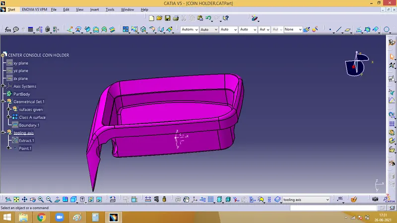
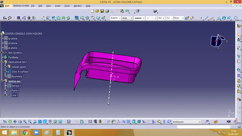
As the base is flat and it at zero degree, a normal line can be created, which asts as a tooling axis
3. Performing Draft Analysis for the given Class A surface
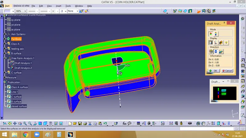
Initially the material mode has to be set and open the feature draft analysis dialog box. Pick on the compass symbol and place it in line with the tooling axis.
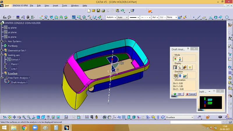
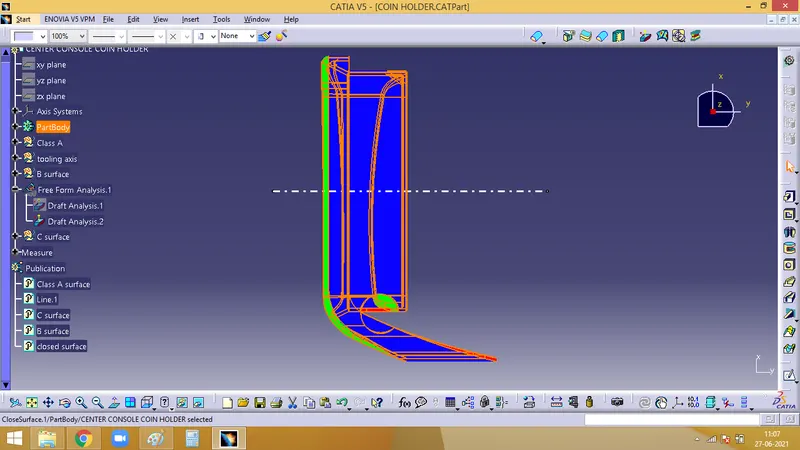
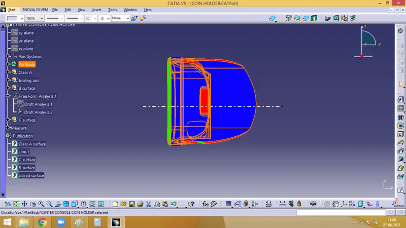
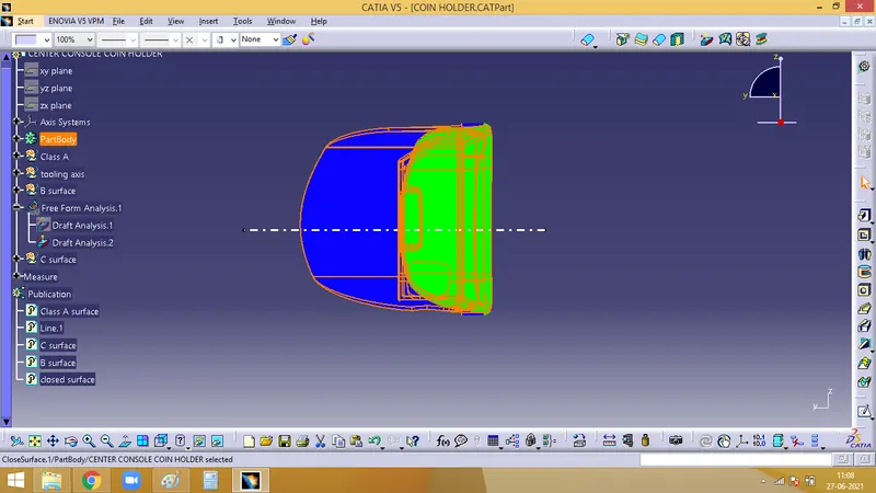
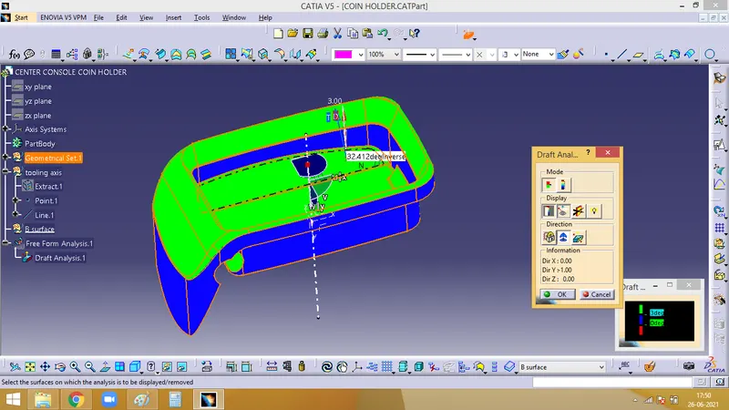
Now we have to check for the draft. Click on the surface and check for the colour from the draft analysis 2 dialog box. The minimum draft needed is 3, which is checked here. If any surface is red, then it has a draft angle less than 3.
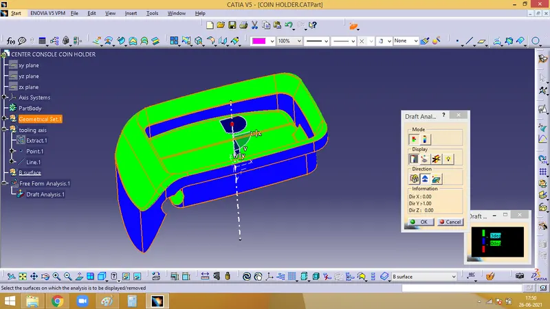
With the help of Analysis under the running point icon, we can check the draft angle of each face
4. Creating Class B surface
In order to avoid issues created by the fillets, simpler patches are created
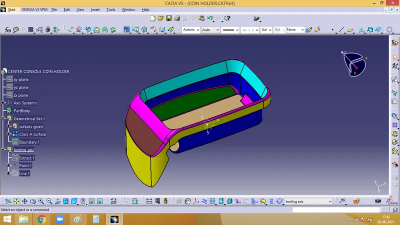
Extract the side walls in blue colour, untrim it, extrapolate.
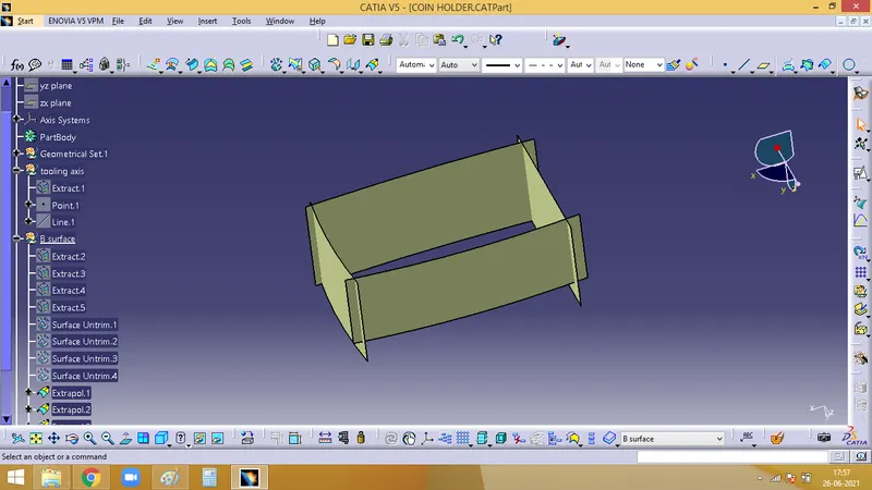
Then the expolated components are trimmedand offsetted to 2.5 mm
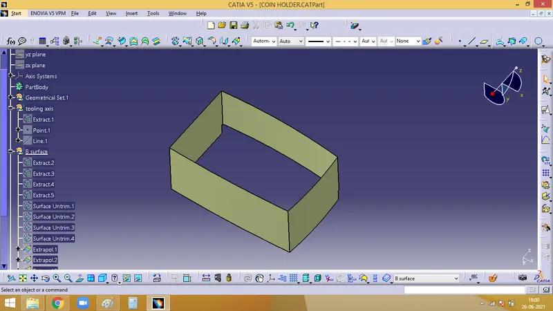
Next, to work on work on base, similarly, the base can be extracted, untrimmed, extrapolated, offsetted and finally trimmed
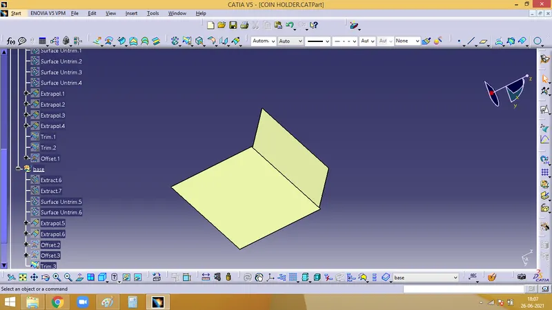
Now, we need to extract the top walls in cean colour and do the same procedure as before.
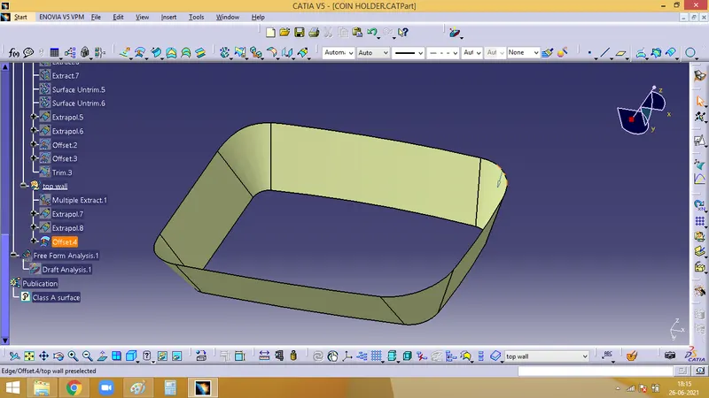
Ensure that all the offset created are on the B side of the class A
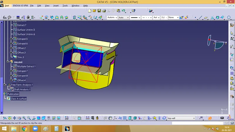
The trim for class B between side walls, top wall and base is done and filleted
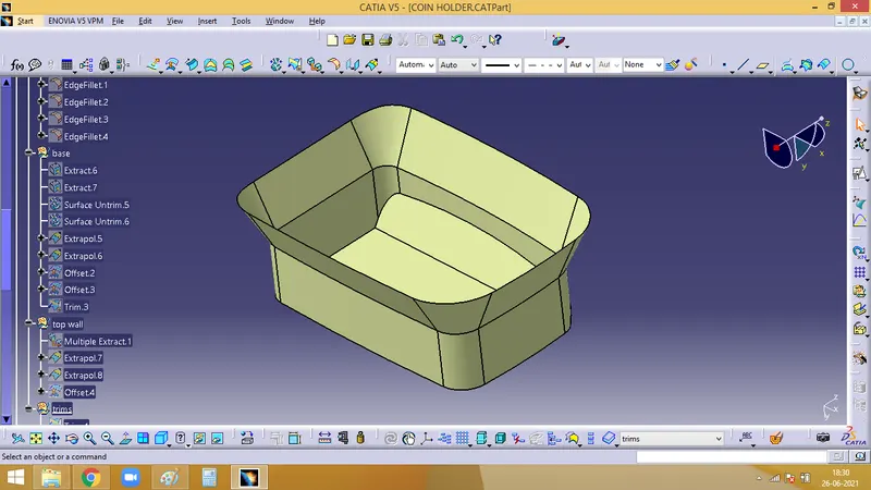
Now, We need to work on the outer flangs i.e. the yellow and the brown patches. Similarly extract it, and it is offsetted.
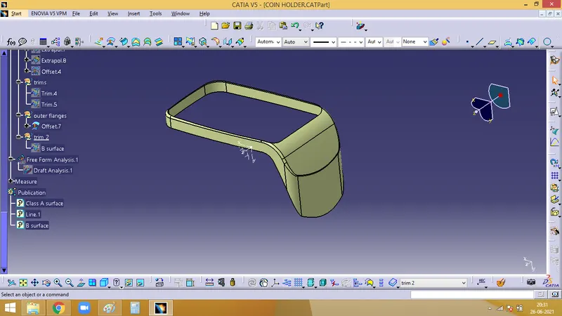
Fianlly, the final trim is done and the fillets are given and the B surface is obtained
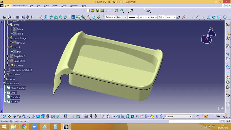
5. Creating Class C surface
For this, create a boundary of the class A surface
Now using sweep command we can create a class C surface.
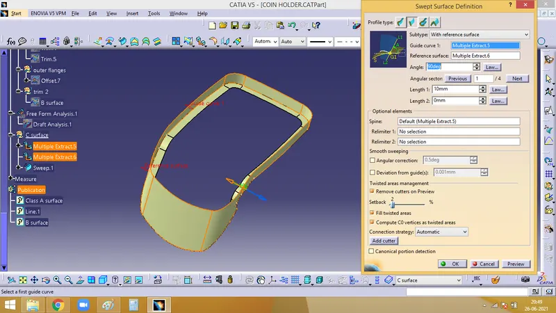
Finally the class C surface is formed
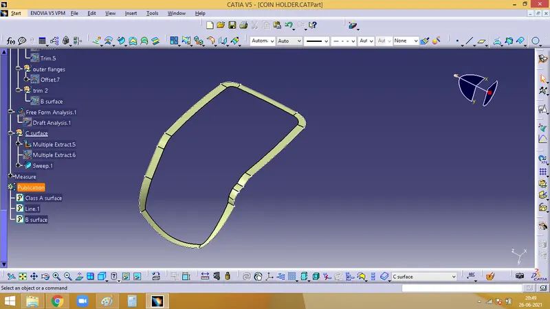
6. Final trim to join class A and class B sing the Class C surface
Now, Class A surface has to be joined with the C surface
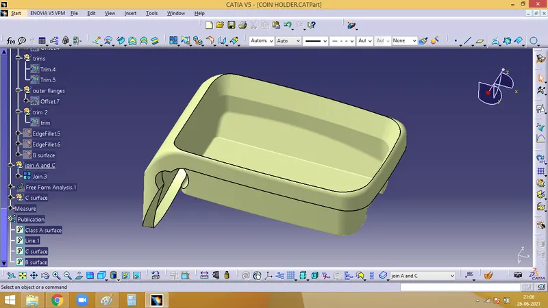
The final trim is done with the join and the B surface
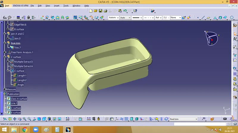
7. For hole
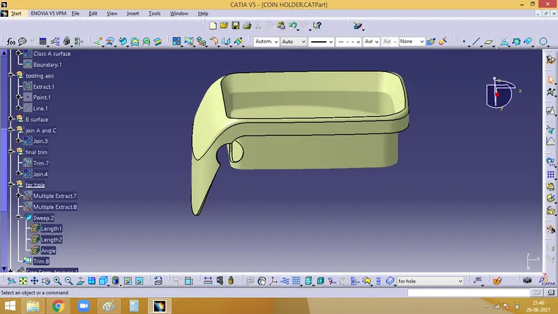
For the hole, from class A, extract the hole and the surfaces sround it and sweep
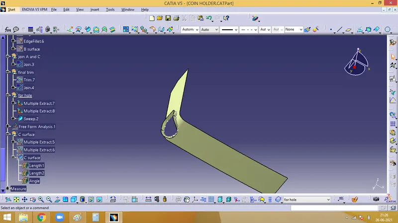
Now, unhide the Fianl join. Ans trim the final join with the sweep of hole created and the final resilt will be as below image
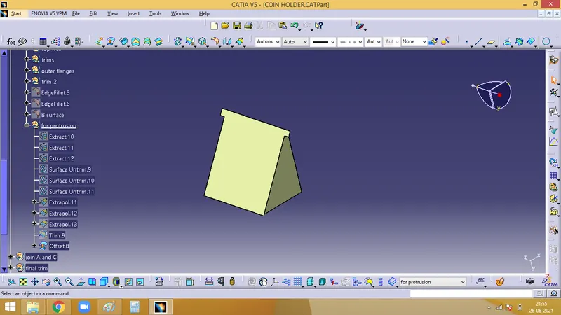
For protrusion :
Extract the walls along the protrusion, untrim it, extrapolate and trim it and offset it, below
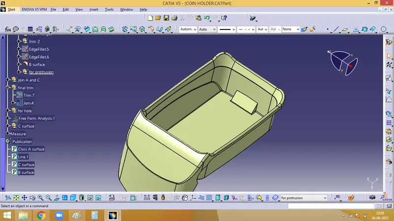
final output will be as
8. Creating a solid body with the closed surface formed
For which we need to first define on the part body, enter into the part work bench, select the closed surface icon on the toolbar and select the final trim that we created.
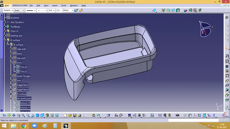
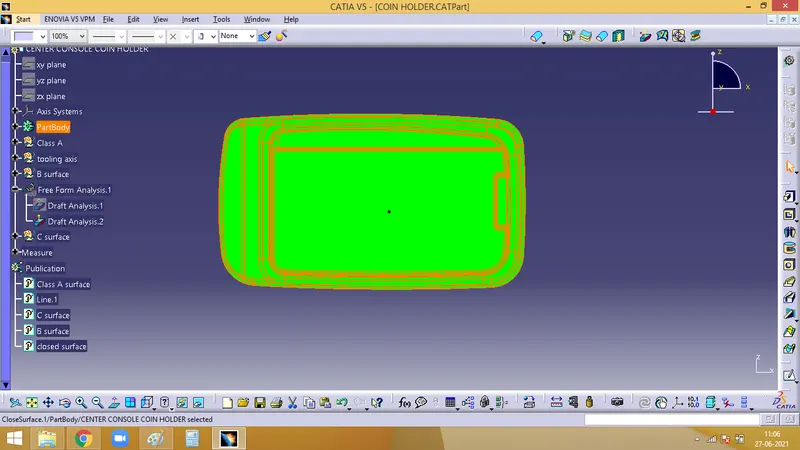
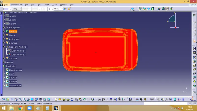
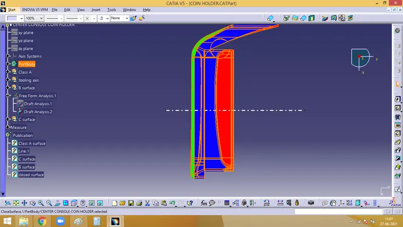
9. Performing Draft Analysis on the final Solid body