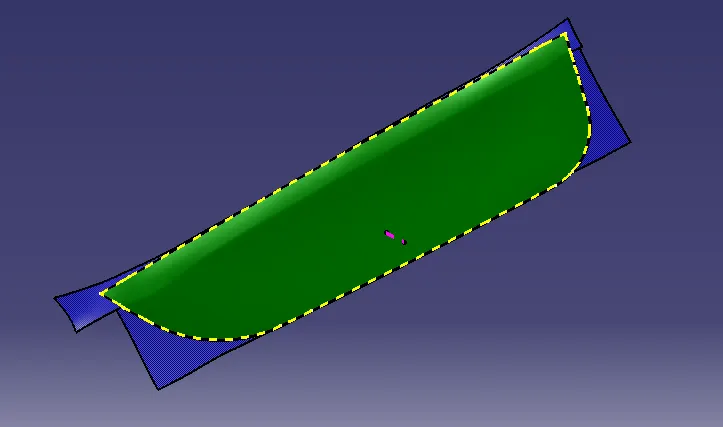
Week 9 Part 4 Project 5 - Attachment Feature Creation
Objective:-
- Create closed body of the Given Driver door Applique.
- Create tooling axis and follow design rules.
- Create Heat Stakes and locators as per design standards.
Content:-
Step 1:-
Creating closed body of the Given Driver Door Applique.
Class-A surface of the given Driver door Applique.
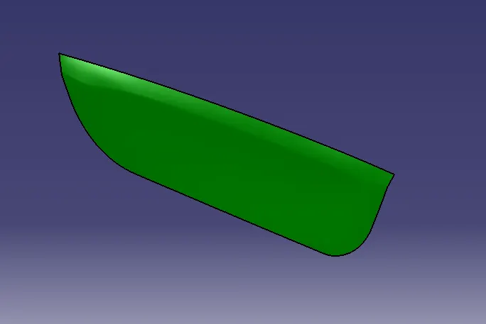
Class-B surface of the given Driver door Applique.
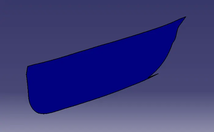
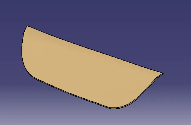
Class-C surface of the given Driver door Applique.
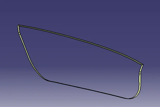
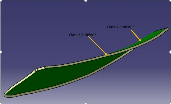
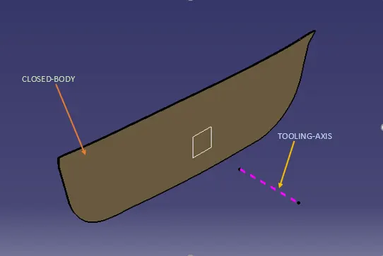
Closed-body of the Given Door Applique.
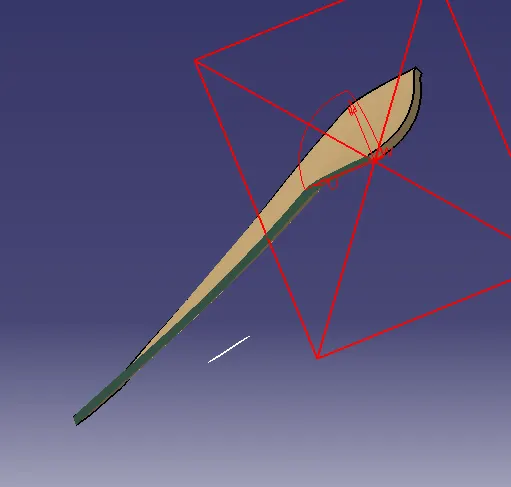
Step 2:-
Creating Tooling Axis of Door Applique.
Step 3:-
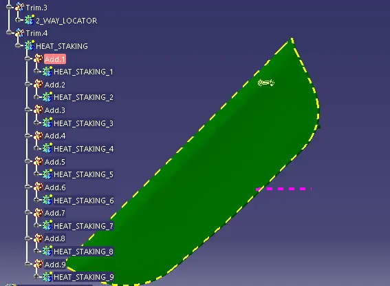
Creating Heat Stacking,4 Way Locator and 2 Way Locator as per Design rule.
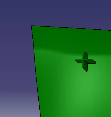
4 way locator:-
2 way locator:-
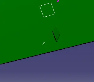
3-2-1 principle is used to assemble this part into the given door attachment.
Main principle of 3-2-1 principle are:-
- support
- Holding(clamping)
- Locating(positioning)
By using two 4-way locator and one 2 way locator translation x ,translation z and rotation along x,y and z direction are restricted,and in order to restrict translation along x+ and x- we design heat steaks.
Heat stakes:
In manufacturing products with thermoplastic components,it is often necessary to join a thermoplastic to a part of dissimilar material,whether it be metal,a dissimilar plastic or other material.
Heat steaking is a process in which one part is provided with studs or bosses which protudes through the holes in the other part.The stud or the boss is then deformed by melting the plastic to form ahead which mechanically locks the two parts together.
Design rule for heat steaks:-
- Minimum 50mm gap should be there between bosses for heat steaks.
- Height of the Heat steak bosses should be less than the height of the Locator (Minimum 5mm).Because first location should take place and then fixation.
- Minimum draft of 0.5 deg should be there.
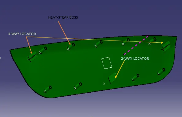
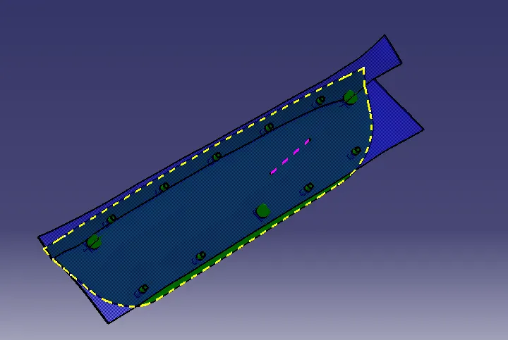
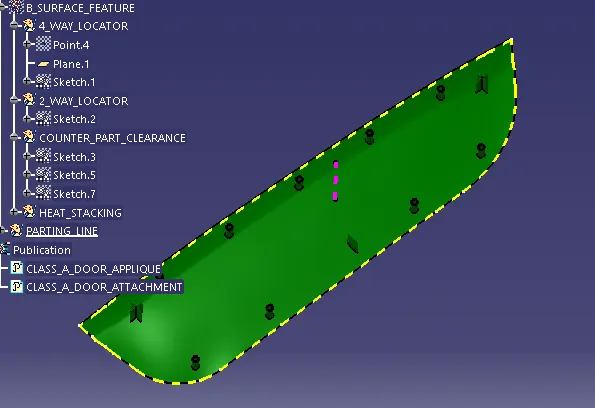
Above picture shows two 4 way locator,one 2 way locator and 8 heat steak bosses for fixing the door applique into door attachment.
Step 4:-
Draft analysis of the given Door Applique.
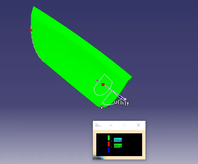
Above picture shows the draft analysis of class-A surface,nominal draft angle is 3 deg,green colour shows that the Class A surface can be clear in the designed tooling direction.
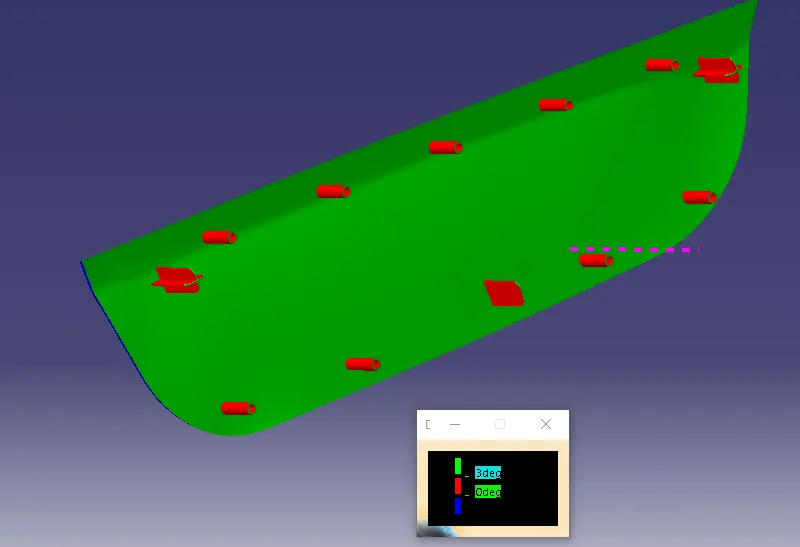
Above picture shows the draft analysis of Class-B surface,nominal draft angle is 3 deg, green colour shows that the part can be clear in the designed tooling direction.
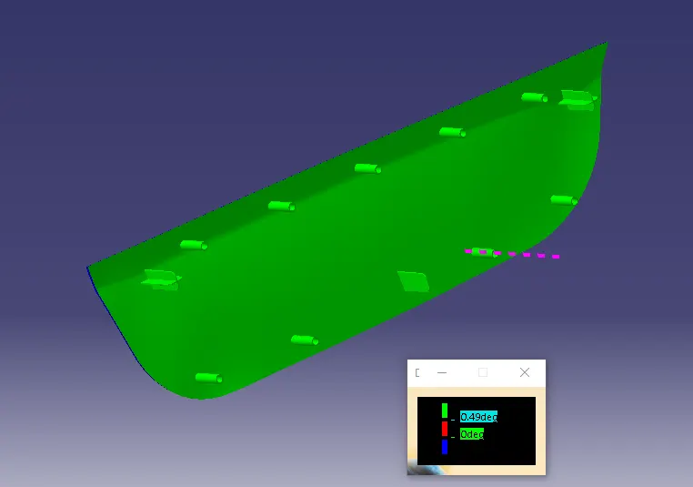
Above picture shows the draft analysis of B-surface feature,nominal diameter is 0.5 deg,green colour shows that the Bsurface feature can be clear in the designed tooling direction.
Step 5:-
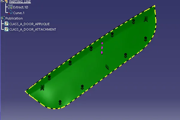
Parting line of Door Applique.
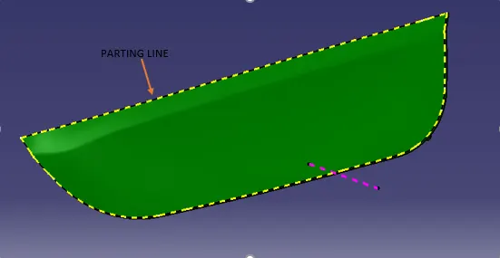
Parting Line:- The parting line is the line in which the two halves of the mold meet,one half is the core and the other half is the cavity.To the extent possible,all features should be oriented perpendicular to the parting line to facilitate removal from the mold.
Step 6:-
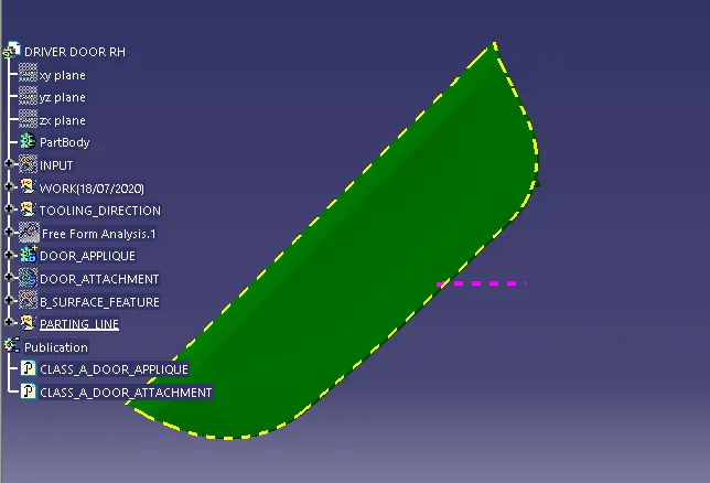
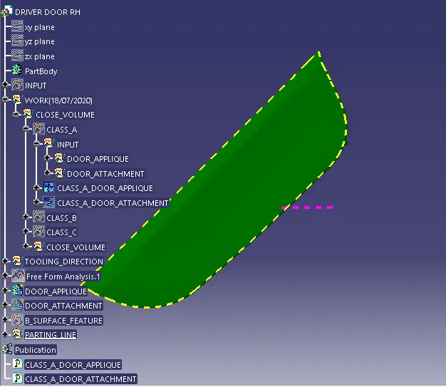
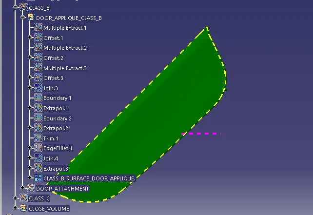
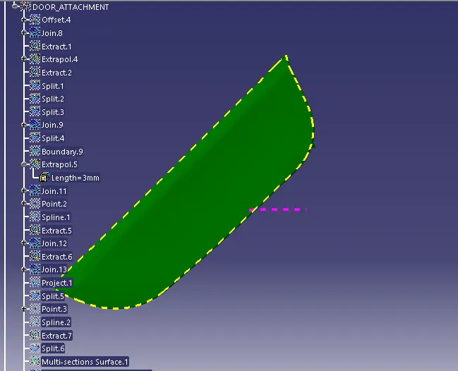
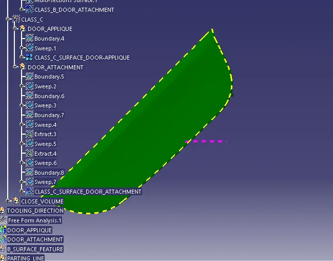
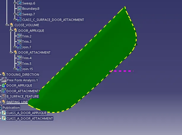
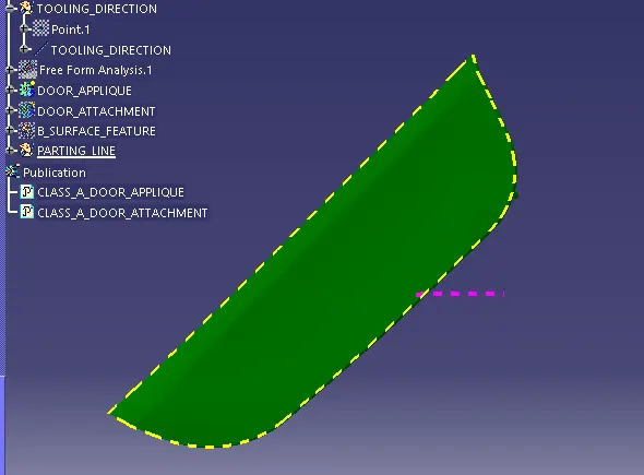
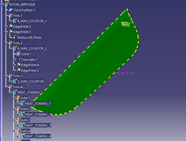
Tree structure for Door Applique.
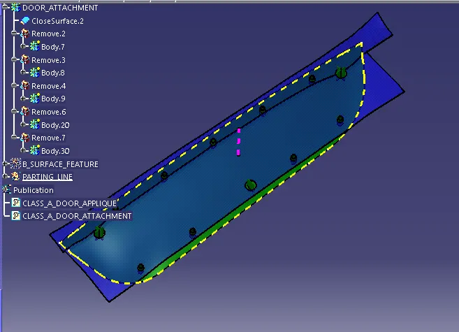
Given below the tree structure of Door Applique.
Final image of Door Applique with Door attachment:-